
 Open Access Article
 This Open Access Article is licensed under a Creative Commons Attribution-Non Commercial 3.0 Unported Licence
Study of mixed matrix membranes with in situ synthesized zeolite imidazolate frameworks (ZIF-8, ZIF-67) in polyethersulfone polymer for CO2/CH4 separation†
Aditya Jonnalagedda and
Bhanu Vardhan Reddy Kuncharam *
*
Department of Chemical Engineering, Birla Institute of Technology & Science, Pilani, Pilani Campus, Rajasthan, 333031, India. E-mail: bhanu.vardhan@pilani.bits-pilani.ac.in; Tel: +91-1596255839
First published on 27th August 2024
Abstract
Biogas, produced from anaerobic digestion, is a sustainable and renewable energy source. To upgrade biogas to Bio-CNG, CO2 must be removed from the raw mixture. Membrane separation is an economical process for the removal of CO2, and mixed matrix membranes (MMMs) are being explored for CO2/CH4 separation. MMMs are fabricated using techniques such as in situ techniques to overcome research gaps, such as in filler agglomeration and filler–polymer interfaces. In this work, MMMs were fabricated using the in situ growth of ZIF-8 and ZIF-67 in polyethersulfone (PES) and compared with traditional filler dispersion of ZIF-8 and ZIF-67. The fabricated MMMs were characterized and tested for gas permeation using a model biogas. Fourier-transform infrared (FTIR) spectroscopy and Field Emission Scanning Electron Microscopy (FESEM) analysis were conducted to confirm in situ synthesis of ZIF-8 and ZIF-67. CO2 permeability of in situ ZIF-8 and ZIF-67-based MMMs have enhanced to 84.5 Barrer and 78.8 Barrer, respectively, compared to pure PES membrane, which is around 25 Barrer. Similarly, ZIF-8 and ZIF-67-based traditional MMMs have shown an increase in the CO2 permeability of 75.6 Barrer and 68 Barrer, respectively. Additionally, the selectivity for CO2/CH4 separation increased for some of the prepared MMMs, demonstrating the effectiveness of the in situ fabrication method.
1 Introduction
The increase in energy consumption (especially from fossil fuels) in the world has resulted in higher than usual greenhouse gas (GHG) emissions and various unfavorable effects, such as melting polar glaciers, climate change, loss of biodiversity, etc.1 Steps are needed to remedy the impact of GHG emissions, such as carbon dioxide capture and switching to renewable energy sources (such as biogas).2 Carbon dioxide is separated using chemical and environmental engineering techniques such as adsorption, absorption, cryogenic separation, bio-separation, and gas separation membranes.3 The membrane separation is one of the cost-effective methods for the removal of carbon dioxide from gas mixtures like biogas (CO2/CH4),4 flue gas (CO2/N2), syngas (CO2/H2), and also for gas mixtures such as oxygen from the air (O2/N2),5 petroleum-based gas separations (C3H6/C3H8).6Commercial polymers such as cellulose acetate (CA), polysulfone (PSF), polyether sulfone (PES, UDEL), polyimide (Matrimid 5218), polyether (block imide) (Pebax MH1657) have been used in gas separation applications. The polymeric membranes employ a solution diffusion mechanism for gas separation,7 which is efficient and low cost but has a trade-off relation between selectivity and permeability, quantified by Robeson et al. 1991 and 2008.8,9 These challenges can be overcome by using mixed matrix membranes (MMMs); MMMs are fabricated by dispersing inorganic fillers such as metal–organic frameworks (MOF) (ZIFs, UiO-66, MILs), silica, zeolites (H-zeolite, Y-zeolite, ZSM-5), etc. in many commercial polymers or synthesized polymers (PIM-1). However, agglomeration at higher filler loading, poor polymer–filler compatibility, polymer rigidification, and the formation of micro-voids and nano-defects may affect the separation performance of the mixed matrix membranes.
Several methods are suggested to overcome these difficulties, such as functionalization of filler, dual filler approach, and in situ synthesis.10 Briefly, the filler particles are added to the polymer solution to fabricate traditional (ex situ) MMMs and in situ MMMs are fabricated including various types such as in situ polymerization – where the growth/coating of filler (mostly MOF) on the surface of the polymer support by using various techniques such as contra diffusion, layer-by-layer coating, etc.,11 in situ synthesis of MOF in the polymer and in situ synthesis of polymer in MOF solution. All these in situ techniques help enhance MMM's properties such as better polymer–MOF interaction, reduce agglomeration and avoid multistep membrane fabrication procedures. For the preparation of MOF in the polymer solution, the synthesis procedure must be simple and have as few steps as possible. So, ZIF-based fillers, especially ZIF-8 and ZIF-67 MOFs are used in various types of applications in catalysis,12,13 sensors,14 and pharmaceuticals15 due to their tuneable pore size, high surface area, and highly chemically and thermally stable. ZIF-8 and ZIF-67 have been widely used in many separation-based studies, such as water remediation and gas adsorption, and as fillers in mixed matrix membranes for gas separation because of their stability in the polymer chain and molecular sieving capability.16
Many in situ-based studies in gas separation membranes are studied to enhance CO2 separation; in Jia et al. 2023,17 a study of in situ interfacial crosslinking via in situ polymerization was done by dispersing NH2-MIL-53 MOF in the polyamic acid (PAA) and then polymerized into polyimide (PI) by thermal imidization forming amine (–NH2) and hydrogen (H2) bonds improving the H2/CO2 separation performance by 400% and CO2 permeability from 3 to 20 Barrer, this study shows the strong interaction of NH2-MIL-53 and PI in the membrane using characterization, gas permeation, and also the effect of the –NH2 group on H2/CO2 selectivity. A similar study was done by coating PAA on the top of porous α-alumina supports and immersing in the metal solution (zinc) and linker (benzimidazole) solution alternatively to form ZIF-7 on the top of the PAA layer and then thermally imidized, CO2 permeability has dropped (from 433 to 74 Barrer) but improved CO2/CH4 selectivity from 29 to 36,18 and a similar study was conducted previously by the same corresponding authors19 group for propylene-selective membranes using polymer-modification-enabled in situ metal–organic framework formation (PMMOF), in situ synthesis of ZIF-8 was done on the porous support coated with 4,4-(hexafluoroisopropylidene)di-phthalic anhydride 2,4,6-trimethyl-1,3-phenylenediamine polymer, both studies show that the ZIF synthesis using PMMOF method has enlarged the free volume of polymer which helped ZIF growth via the absorption of excess Zn-ion sources. In another in situ study, in situ grafting of polyethylene amine on ZIF-8 was done and dispersed in poly(vinyl amine) (PVAm) and coated of modified polysulfone (PSF) substrate, and selectivity of CO2/CH4 improved from 20 to 50. This increase is attributed to the stable porous structure of PEI-g-ZIF-8 particles inside the polymer matrix and showed good compatibility with PVAm. Also, CO2 permeance improved around 3800 GPU.20 In a study done by Xio li et al. for CO2/N2 separation, where MMMs were fabricated using ZIF-8 in situ inserted by functionalized multiwall carbon nanotubes (MWCNTs) (i.e., ZIF-8 is synthesized in the solvent with MWCNTs dispersed) and Pebax polymer for improving the membrane's free volume and to provide CO2 channelling through ZIF-8 particles inside the smooth surface of MWCNTs. The functional groups of MWCNTs have given dispersion and without agglomerates of filler particles in MMMs. This has improved CO2 permeability to 186.3 Barrer from 80 Barrer, selectivity CO2/N2 from 30 to 61.3 and has surpassed Robeson upper bound.21 In situ synthesis of UiO-66 was done in polyimide polymer (Matrimid 5218), and MMMs were fabricated using the drop-casting method on Petri dishes, where ideal CO2/N2 selectivity and CO2 permeability of 11 wt% in situ UiO-66/PI was found at 36 and 24 Barrer, respectively, improved from 34 and 19 Barrer for 11 wt% UiO-66/PI.22 This paper provides good insights into growing of UiO-based MOF in PI polymer using a novel approach. To enhance the filler/polymer interfacial compatibility and decrease the agglomerates of ZIF-8 MOFs, an in situ technique was used to synthesize ZIF-8 particles in the Pebax-2533 (by one-pot synthesis), and MMMs were cast on fabricated PES support layer for CO2/CH4 separation studies, where CO2 permeability and CO2/CH4 selectivity was enhanced by 155% and 144% respectively at 8 bar feed pressure overcoming Robeson lower bound.23
The literature survey for some of the above in situ studies shows the gas separation potential of ZIF-based MOFs and their compatibility with various polymers, which leads to various explorations for its in situ fabrication to enhance its properties for CO2/CH4 separation. Most of the available investigations have focused on the fabrication of in situ MMMs with PI and Pebax polymers and studies for gas separation mostly with pure gases at high pressures. However, in situ synthesis of MOF in PES polymer and fabrication of its MMMs for CO2 separation has not been demonstrated yet and studied for CO2/CH4 separation with mixed gas at lower pressures based on our literature survey. To address this research gap, in the current study, in a novel approach, MMMs were prepared using in situ growth of ZIF-8 and ZIF-67 nanoparticles in PES polymer and also by traditional route, i.e., dispersion of ZIF-8, ZIF-67 nanofillers in PES. CO2/CH4 separation studies were done by testing gas permeation with model biogas (60![[thin space (1/6-em)]](https://www.rsc.org/images/entities/char_2009.gif) :40–CH4:CO2 in vol%) as a feed mixture at pressure differences of 0.5–1.5 bar. Performance analysis of MMMs was done by comparing gas permeation results of in situ and non-in situ MMMs.
:40–CH4:CO2 in vol%) as a feed mixture at pressure differences of 0.5–1.5 bar. Performance analysis of MMMs was done by comparing gas permeation results of in situ and non-in situ MMMs.
2 Experimental
2.1. Materials
Zinc nitrate hexahydrate (99%, Zn(NO3)2·6H2O), 2-methylimidazole (99%, 2-MeIM), and cobalt nitrate hexahydrate (Co(NO3)2·6H2O) was purchased from Merck Life Science Private Ltd, India. Polyethersulfone (PES) was purchased from Solvay Chemicals, India. Solvents such as methanol (CH3OH) and dimethyl formamide (DMF) were obtained from Merck Life Science Private Ltd, India, and Rankem Chemicals, India, respectively. Mixed gas (CO2/CH4) used for the gas permeation test was procured from Ankur Speciality Gases and Technologies Private Ltd, Jaipur, India.2.2. Synthesis of ZIF-8 and ZIF-67
The synthesis of ZIF-8 filler was adapted using literature24 where 0.68 g of zinc nitrate hexahydrate and 1.5 g of 2-methylimidazole were mixed in 50 ml of methanol separately. After the solids had been dissolved, the two solutions were combined and stirred overnight until the reaction mixture to the opaque solution. The opaque solution mixture was centrifuged at 7000 rpm for 5 minutes and washed with methanol. The resulting wet solids were dried in an air oven at 70 °C to eliminate any remaining methanol; the air-dried solids were then dried for an additional night at 100 °C.Synthesis of ZIF-67 was derived from the literature,25 where 0.5 g of cobalt nitrate hexahydrate was dissolved in the 25 ml of methanol (reddish brown solution) and 1 g of 2-methylimadozle was dissolved in 25 ml methanol (transparent solution). The two mixtures were mixed into a conical flask and stirred overnight (the solution immediately turned purple). The stirred mixture is then centrifuged and washed with methanol using the same process as previously mentioned to synthesize ZIF-67.
2.3. Fabrication of pure PES, ZIF-8, ZIF-67/PES MMMs
Pure PES membrane was prepared by dissolving 3 g of PES polymer powder in 15 ml of DMF solvent using the priming method at 50 °C. After completely dissolving the polymer, the solution was stirred for an additional 5 hours to avoid polymer lumps. The polymer solution was degassed in a vacuum chamber for around 1 hour to eliminate air bubbles formed due to stirring. The polymer dope solution was cast on a flat Petri dish and placed in a vacuum oven at 60 °C for two days for solvent evaporation, draining the solvent in between to form a dense PES membrane, which was peeled off the Petri dish.ZIF-8 and ZIF-67-based mixed matrix membranes (MMMs) were synthesized by suspending predetermined amount of MOF-filler in 15 ml of DMF (for 1, 2, 4, 5, 10, 15, and 20 wt%) using eqn (1). The MOF solution was sonicated for 1 hour, and then 3 g of polymer was added to the MOF solution and stirred overnight. The MOF–polymer mixture was sonicated for 3 hours and degassed for 1 hour; the same membrane casting and drying procedure was followed for pure PES membrane. The fabrication technique of MMMs is shown in Fig. 1a
 | (1) |
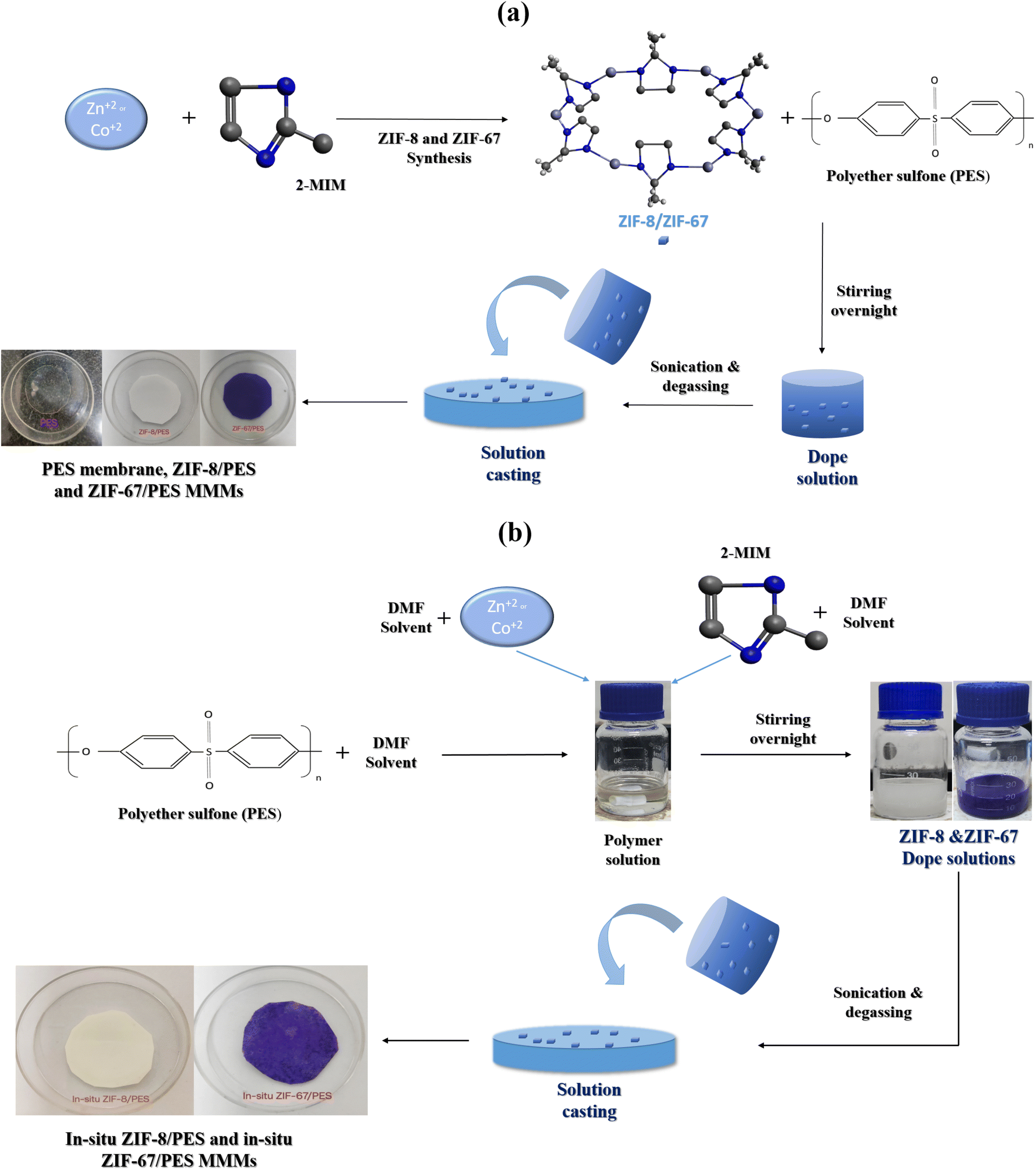 | ||
| Fig. 1 Schematic for preparation of MMMs via (a) traditional method and (b) in situ method. | ||
2.4. Synthesis in situ ZIF-8 and ZIF-67 in PES polymer solution and MMMs fabrication
A novel in situ synthesis method for ZIF-8 and ZIF-67 was developed with various optimizations, in which a predetermined amount of metal precursor (zinc nitrate salt for ZIF-8 and cobalt nitrate salt for ZIF-67) and linker (2-MeIM) separately in 2.5 ml DMF solution based on yields obtained for synthesis of ZIF-8 (16.6%) and ZIF-67 (15.62%).23 In this method, 3 g of PES polymer was pre-dried at 50 °C and then dissolved in 10 ml of DMF using a priming technique. After stirring for 1 hour, both solutions (metal and linker) were mixed together in a polymer solution and stirred for 1 hour to form MOF particles, followed by overnight stirring for the uniform mixture. A similar procedure was used as the PES membrane was cast with a dope solution, and the same drying temperature was used, but the in situ membrane drying time was three days. Further, MMMs were dried overnight in an air oven at 50 °C to remove additional solvent trapped in pores. The fabrication of MMMs using in situ technique is shown in Fig. 1b.2.5. Characterization of ZIF-8, ZIF-67 and characterization of all membranes
X-ray diffraction (XRD) characterization was done for ZIF-8 and ZIF-67 MOFs using a tabletop Rigaku Miniflex X-ray diffractometer using Cu-Kα radiation (λ = 1.54 Å) with 30 kV and 15 mA to analyse the crystal structure, XRD spectra was collected in range 5–40° at a scanning rate of 2° per minute. Fourier Transform Infrared spectroscopy (FTIR) analysis was done for ZIF-8, ZIF-67, and all prepared MMMs to confirm the chemical bonding present in the MOFs and MMMs using a PerkinElmer Frontier Spectrometer where the sample is prepared using a KBr press (Model M-15) and data was acquired in the 400–4000 cm−1 IR zone. The glass transition temperature (Tg) for all membranes was obtained using a differential scanning calorimeter (DSC) (PerkinElmer DSC 400), in the temperature range 30–270 °C with nitrogen at 20 ml min−1 with heating and cooling rate of 10 °C min−1. The morphology of the membranes was characterized using Field Emission Scanning Electron Microscope (FESEM, FEI-ApreoLoVac model), where all the membranes were placed on stubs with carbon tape and coated with gold in a vacuum chamber for 30 seconds; the coated grids were placed at a 45° angle to electron gun to obtain the cross-sectional morphology of membranes.2.6. Gas permeation tests
A detailed schematic of the gas permeation setup is reported in our previous study.26 The fabricated membranes were placed between two rubber gaskets where gas permeation experiments were carried out by sending feed of mixed gas with a composition of CO2:CH4–40:60 by regulating a flow of 13 cc min−1 using mass flow controller (MFC) and pressure difference of 0.5, 1 and 1.5 bar between permeate and feed chamber were maintained using a Back Pressure Regulator (Swagelok-BPR). Nitrogen is used as a sweep gas in the permeate chamber. Permeate and retentate streams are connected to gas chromatography with a TCD detector (Shimadzu 2014) to analyse their concentrations and also to permeate side to the bubble flow meter to measure the permeate flow, which is used to measure membranes gas permeability and selectivity using eqn (2) and (3), respectively.26
 | (2) |
Selectivity (αCO2/CH4, no units) is the ratio of permeabilities of CO2 and CH4.
 | (3) |
3 Results and discussion
3.1. Characterization of MOFs and membranes
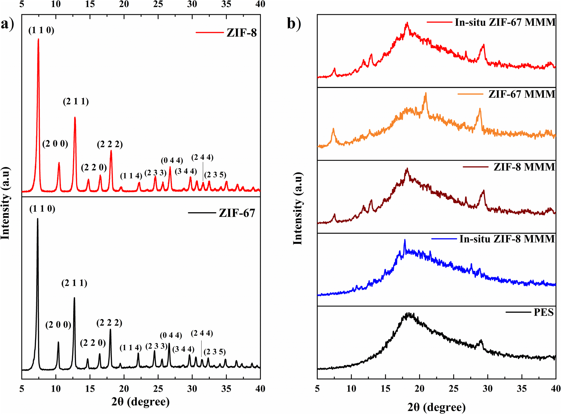 | ||
| Fig. 2 XRD of (a) MOFs and (b) membranes. | ||
 | ||
| Fig. 3 FTIR of (a) ZIF-8 and ZIF-67, (b) pure PES and MMMs. | ||
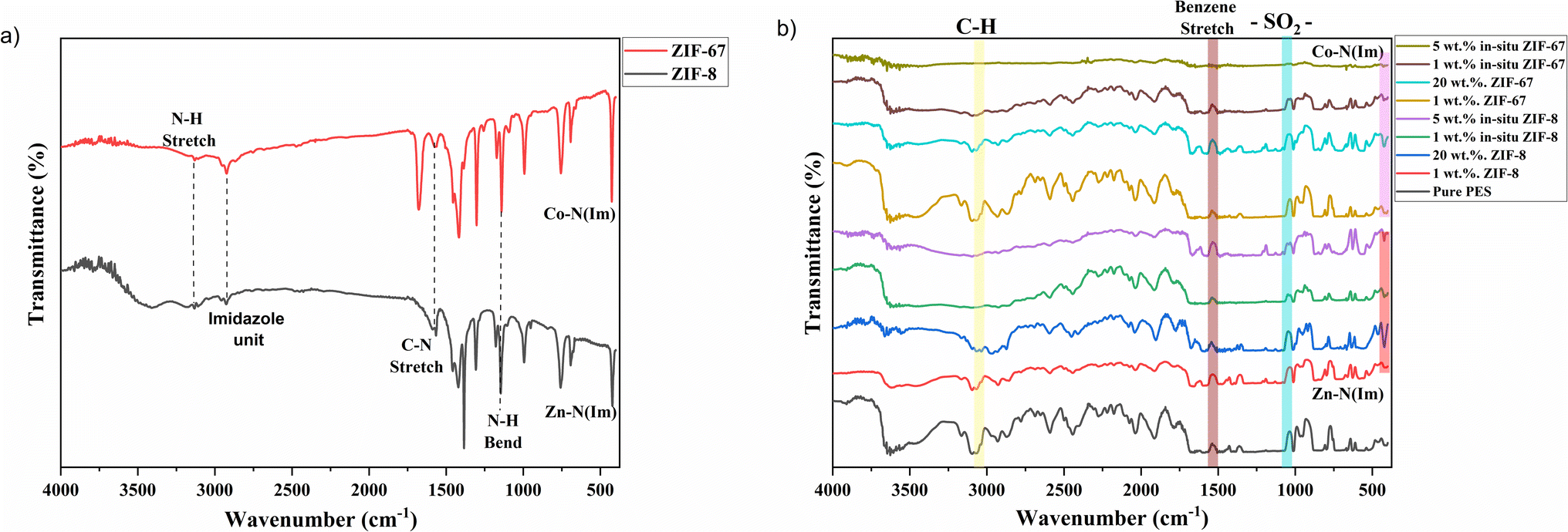
Fig. 3b shows the FTIR spectra of pure PES membranes, 1 wt% and 20 wt% of ZIF-8 and ZIF-67/PES MMMs and 1 wt% and 5 wt% of in situ ZIF-8 and ZIF-67/PES MMMs. In the FTIR plot, we can see that all characteristic peaks of PES polymer, i.e., C–N stretch (around 3000 cm−1), benzene ring stretch (at about 1510 cm−1), and –SO2– (1095 cm−1)32 are present in all membranes after introducing the fillers. No additional peaks or peak shifting were observed except for bonds around 420–425 cm−1 (present only in MMMs), which are attributed to metal linker Zn–N (Im)/Co–N (Im) bonding, as mentioned in the above section. The FTIR spectra of MMMs also show no additional peaks, indicating the addition of filler has not hampered the structural chain of the polymer and filler particles have settled within the free volume of the polymer, which corresponds to the XRD results where MMMs peaks still represent the amorphous nature of the polymer.
| Membrane | Tg (°C) |
|---|---|
| Pure PES | 220.5 ± 0.6 |
| 1 wt% ZIF-8 PES | 223.1 ± 0.7 |
| 20 wt% ZIF-8 PES | 230.9 ± 0.2 |
| 1 wt% in situ ZIF-8 PES | 225.2 ± 0.9 |
| 5 wt% in situ ZIF-8 PES | 227.4 ± 0.4 |
| 1 wt% ZIF-67 PES | 223.9 ± 0.3 |
| 20 wt% ZIF-67 PES | 233.8 ± 0.5 |
| 1 wt% in situ ZIF-67 PES | 227.6 ± 0.3 |
| 5 wt% in situ ZIF-67 PES | 229.4 ± 0.4 |
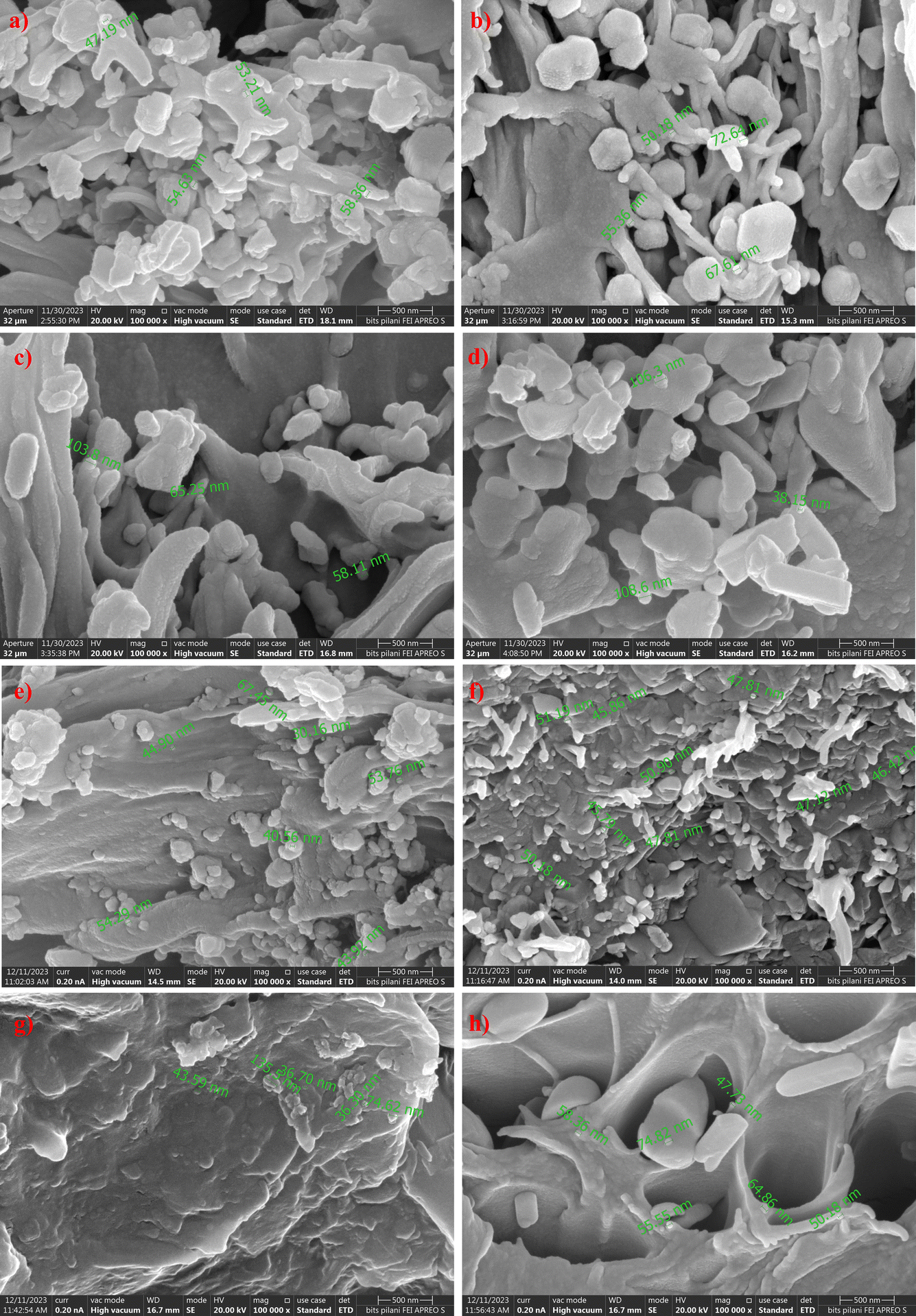 | ||
| Fig. 4 FESEM images—cross-section view of (a and b) 1, 20 wt% ZIF-8 MMMs, (c and d) 1, 5 wt% in situ ZIF-8 MMMs, (e and f) 1, 20 wt% ZIF-67 MMMs, (g and h) 1, 5 wt% in situ ZIF-67 MMMs. | ||
We can also observe the growth of ZIF-particles in polymer; in Fig. 4c and d, we can see that the particle growth of in situ ZIF-8 has increased compared to ZIF-8 in traditional (ex situ) MMMs due to an increase in stirring time, temperature and also change in solvent35 which led to Sono-crystallization.36 In situ ZIF-67 particles have shown a huge rough growth rate at higher metal concentration37 which led to the formation of defects in the membrane, as shown in Fig. 5h. Despite the formation of defects in 5 wt% in situ ZIF-67 MMM due to the rough growth rate, XRD and FTIR spectra of the membrane show that there is no structural damage within polyethersulfone polymer.
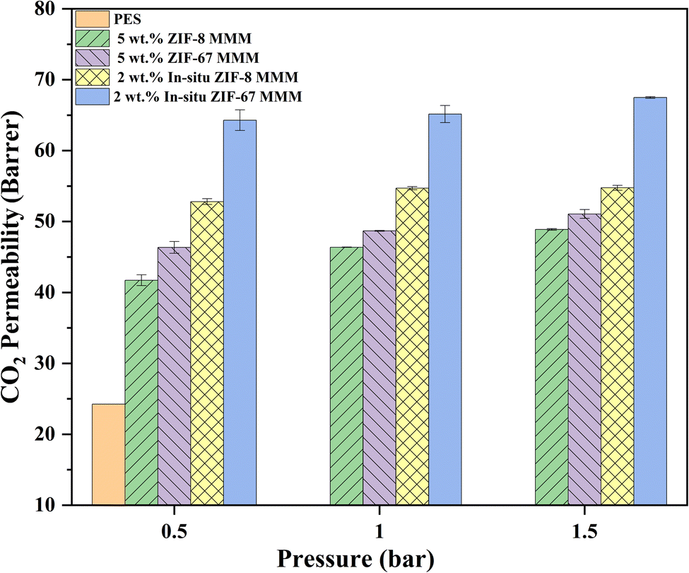 | ||
| Fig. 5 Variation of CO2 permeability of MMMs with the increase of pressure. | ||
3.2. Gas permeation experiments
| Membrane | CO2 permeability (Barrer) | CO2/CH4 selectivity | ||||
|---|---|---|---|---|---|---|
| 0.5 bar | 1 bar | 1.5 bar | 0.5 bar | 1 bar | 1.5 bar | |
| Pure PES | 24.2 ± 0.27 | 25.7 ± 0.5 | 25.4 ± 0.63 | 12.23 | 14.14 | 12.61 |
| 1 wt% ZIF-8/PES | 28.9 ± 0.99 | 21.9 ± 0.49 | 31.5 ± 0.68 | 11.47 | 13.06 | 10.38 |
| 2 wt% ZIF-8/PES | 37.2 ± 1.63 | 39.9 ± 0.62 | 39.6 ± 0.54 | 10.55 | 10.04 | 10.76 |
| 4 wt% ZIF-8/PES | 39.6 ± 0.6 | 40.3 ± 0.05 | — | 11.09 | 11.43 | — |
| 5 wt% ZIF-8/PES | 41.7 ± 0.76 | 46.4 ± 0.02 | 48.9 ± 0.11 | 11.36 | 11.51 | 10.33 |
| 10 wt% ZIF-8/PES | 61.9 ± 0.31 | 65.7 ± 0.9 | 67.4 ± 0.67 | 11.78 | 11.32 | 9.60 |
| 15 wt% ZIF-8/PES | 75.6 ± 1.59 | 77.4 ± 0.5 | — | 13.76 | 11.96 | — |
| 20 wt% ZIF-8/PES | 47.7 ± 1.28 | — | — | 12.28 | — | — |
| Membrane | CO2 permeability (Barrer) | CO2/CH4 selectivity | ||||
|---|---|---|---|---|---|---|
| 0.5 bar | 1 bar | 1.5 bar | 0.5 bar | 1 bar | 1.5 bar | |
| Pure PES | 24.2 ± 0.27 | 25.7 ± 0.5 | 25.4 ± 0.63 | 12.23 | 14.14 | 12.61 |
| 1 wt% ZIF-67/PES | 22.0 ± 1.27 | 23.3 ± 0.02 | 26.0 ± 0.06 | 10.02 | 9.49 | 13.14 |
| 2 wt% ZIF-67/PES | 32.9 ± 0.09 | 33.8 ± 0.34 | 28.6 ± 0.04 | 10.46 | 11.44 | 11.84 |
| 4 wt% ZIF-67/PES | 34.8 ± 0.23 | — | — | 11.50 | — | — |
| 5 wt% ZIF-67/PES | 46.9 ± 0.83 | 48.7 ± 0.06 | 51.1 ± 0.65 | 15.82 | 12.87 | 11.54 |
| 10 wt% ZIF-67/PES | 54.8 ± 2.17 | 54.2 ± 0.58 | 55.1 ± 1.4 | 13.23 | 11.74 | 12.27 |
| 15 wt% ZIF-67/PES | 68.0 ± 1.88 | 70.5 ± 0.26 | 65.4 ± 0.63 | 14.58 | 13.51 | 13.39 |
| 20 wt% ZIF-67/PES | 54.4 ± 0.88 | — | — | 14.58 | — | — |
In Table 3, we can see the CO2 permeability and CO2/CH4 selectivity of ZIF-67/PES MMMs where the addition of ZIF-67 filler has initially decreased CO2 permeability from 24 Barrer to 22 Barrer (8% decrease) which can happen for lower filler loading (1 wt%) due to restricted polymer chain mobility.40 We can see the increment of permeability from 2 wt% ZIF-67 filler loading to 33 Barrer, which is a 37% increase, and also the highest CO2 permeability of 68 Barrer (183% increase) at 15 wt% MOF loading and a decrease of 21% at 20 wt% ZIF-67, i.e., from 68 to 54 Barrer, which might be due to polymer rigidification (same as ZIF-8 MMMs) where the Tg value was increased to 234 °C (from 220 °C). CO2/CH4 selectivity of ZIF-67-based MMMs has risen from 12 to 16 (33% increase) at 5 wt% of ZIF-67, which can be attributed to a size-sieving mechanism of ZIF MOF as mentioned above, selectivity of CO2/CH4 at 20 wt% was slightly decreased (of 6%) to 14.7. All other ZIF-67 MMMs selectivity was around 13–14, higher than pure PES membrane – the reason for the drop of selectivity at 20 wt% ZIF-67 MOF may be due to agglomeration, which can be seen in Fig. 4f, and also, we can observe that the particle size of ZIF-67 in 20 wt% ZIF-67/PES MMM has almost remained within the same range as 1 wt% ZIF-67 MMM. This can be why CO2/CH4 selectivity has remained at 15 and not declined below 12.
| Membrane | CO2 permeability (Barrer) | CO2/CH4 selectivity | ||||
|---|---|---|---|---|---|---|
| 0.5 bar | 1 bar | 1.5 bar | 0.5 bar | 1 bar | 1.5 bar | |
| 1 wt% in situ ZIF-8/PES | 33.3 ± 2.43 | 34.3 ± 0.33 | 35.9 ± 0.06 | 11.21 | 12.21 | 10.75 |
| 2 wt% in situ ZIF-8/PES | 65.3 ± 1.45 | 65.2 ± 1.21 | 67.5 ± 0.12 | 9.11 | 9.60 | 10.43 |
| 4 wt% in situ ZIF-8/PES | 84.1 ± 1.2 | 84.5 ± 0.71 | — | 15.21 | 15.57 | — |
| 5 wt% in situ ZIF-8/PES | 61.2 ± 2.46 | — | — | 13.97 | — | — |
| Membrane | CO2 permeability (Barrer) | CO2/CH4 selectivity | ||||
|---|---|---|---|---|---|---|
| 0.5 bar | 1 bar | 1.5 bar | 0.5 bar | 1 bar | 1.5 bar | |
| 1 wt% in situ ZIF-67/PES | 27.6 ± 0.8 | 29.3 ± 0.21 | 28.6 ± 0.87 | 11.66 | 12.96 | 11.56 |
| 2 wt% in situ ZIF-67/PES | 52.8 ± 0.42 | 54.7 ± 0.22 | 54.8 ± 0.35 | 12.76 | 12.83 | 12.18 |
| 4 wt% in situ ZIF-67/PES | 73.7 ± 0.41 | 78.8 ± 0.93 | — | 13.47 | 16.39 | — |
| 5 wt% in situ ZIF-67/PES | 79625.6 ± 668.1 |
— | — | 1.11 | — | — |
In situ ZIF-67-based mixed matrix membranes (MMM) have also shown an increase in the CO2 permeability (same as in situ ZIF-8 PES MMMs) at 1 wt% and 2 wt% in situ ZIF-67 MMMs, the permeability of CO2 was increased from 24 Barrer (pure PES membrane) to 27.8 Barrer and 52.8 Barrer with 16% and 120% increase with respect to PES membrane respectively. The highest permeability of CO2 of 73.7 Barrer was observed at 4 wt% in situ ZIF-67, which is a 207% increase. The CO2/CH4 selectivity also showed an increasing trend for 1, 2, and 4 wt% of in situ ZIF-8 is 11.6, 12.76, and 13.47, respectively. This trend might be due to the molecular sieving capacity of ZIF-67 and the adsorption capacity of CO2 over CH4.42 For 5 wt% in situ ZIF-67 MMM has given CO2 permeability of 79625 Barrer and CO2/CH4 selectivity of 1.11, correspond to FESEM image Fig. 4h, where the membrane has formed defects due to in situ ZIF-67 (as discussed in FESEM section) which has allowed passage for both CO2 and CH4 gases.
Fig. S3(c and d)† shows the comparison study of all ZIF-67-based MMMs (in situ and non-in situ). Similar to the ZIF-8, in situ ZIF-67-based MMMs have shown greater CO2 permeability than normal ZIF-67 MMMs due to the presence of various organic groups such as imidazole, triazine, adenine, and various others due to Lewis's acid attractions. Unlike ZIF-8, the permeability of CO2 has shown an increasing trend where CO2 permeability was enhanced for 1, 2, 3 wt% in situ ZIF-67 MMMs compared to non-in situ ZIF-67 MMM from 22 to 27.6 Barrer, 32.9 to 52.8 Barrer and 34.8 to 73.7 Barrer, respectively. The 5 wt% in situ ZIF-67/PES MMM has shown an exponential increase of CO2 permeability of 79625 Barrer formation of defects (FESEM image, Fig. 4h) which occurred due to the growth of ZIF-67 in PES. CO2/CH4 selectivity of in situ ZIF-67/MMMs has enhanced similarly to all previously reported literature47 The enhancement of CO2 permeability is attributed to the pore walls of ZIF-67 being slightly electropositive, which is implied due to the availability of Co2+ sites as discussed previously, have electronegativity, which provides various transport channels for CO2 transport.
| Membrane | Preparation technique (FS-flat sheet, HF-hollow fiber) | Testing pressure (bar) | Feed type (P-pure/single gas, M-mixed gas) | Permeability, PCO2 (Barrer) | Selectivity αCO2/CH4 | Reference |
|---|---|---|---|---|---|---|
| ZIF-7/PAA | ZIF-7 preparation on PI coated on α-alumina (FS) | 1 | P | 74 | 36 | 18 |
| NH2-ZIF-8/PVAm/mPSF | In situ grafting of PeA on ZIF-8 and coated on PVAm/mPSF (FS) | 10 | P | 3800 GPU | 50 | 20 |
| ZIF-8/Pebax | One pot synthesis of ZIF-8 in Pebax polymer (FS) | 10 | P | 158 | 25 | 23 |
| ZIF-8/PSF | The traditional way of mixed matrix membrane (FS) | 0.5 | M | 25 | 12 | 34 |
| NH2ZIF-8/PSF | The traditional way of mixed matrix membrane (FS) | 0.5 | M | 21 | 14 | 34 |
| ZIF-8/CA | The traditional way of mixed matrix membrane (FS) | 0.5 | M | 9.5 | 15.3 | 40 |
| ZIF-8/Pebax | The traditional way of mixed matrix membrane (FS) | 11 | P | 130 | 18.6 | 47 |
| ZIF-67/Pebax | The traditional way of mixed matrix membrane (FS) | 11 | P | 162 | 25 | 47 |
| ZIF-8/PES | Dip coating of ZIF-8 on porous PES membrane (FS) | 2 | M | 22 GPU | 14.6 | 48 |
| ZIF-8/PEI | The traditional way of mixed matrix membrane (FS) | 1 | M | 0.8 | 12.5 | 49 |
| ZIF-67/PEI | The traditional way of mixed matrix membrane (FS) | 1 | M | 0.5 | 10.4 | 49 |
| ZIF-67/PSF-GO | In situ growth of ZIF-67 on PSF/GO (HF) | 1 | M | 39.3 GPU | 44.9 | 50 |
| ZIF-8/PSF | The traditional way of mixed matrix membrane (FS) | 4 | P | 29.22 | 23.16 | 51 |
| ZIF-8/PES | The traditional way of mixed matrix membrane (FS) | 1.5 | M | 75.6 | 13.8 | Present work |
| ZIF-67/PES | The traditional way of mixed matrix membrane (FS) | 1.5 | M | 68 | 14.6 | Present work |
| In situ ZIF-8/PES | In situ synthesis of ZIF-8 in PES (FS) | 2 | M | 84.5 | 15.6 | Present work |
| In situ ZIF-67/PES | In situ synthesis of ZIF-67 in PES (FS) | 2 | M | 78.8 | 16.4 | Present work |
Compared to the literature, we can see that filler-induced (especially ZIF-8 and ZIF-67) and in situ mixed matrix membranes have shown superior performance for the separation of CO2 compared to pure polymeric membranes. In summary, various in situ strategies (even other MOFs) for the fabrication of MMMs have more effective ways to improve their performance.
4 Conclusion
This paper demonstrated the preparation and characterization of in situ ZIF-8, and ZIF-67 MMMs and their significance in CO2/CH4 separation via gas permeation experiments. The membranes were characterized using FTIR for conformation of ZIF-8 and ZIF-67 in membranes and FESEM for the difference in particle size of ZIF-8 and ZIF-67 in different filler loadings and in situ preparation. DSC was done in membranes to find changes in glass transition temperature (Tg). The properties of traditional and in situ MMMs can be seen via FESEM and DSC results, where different morphology for in situ grown ZIF-8 and ZIF-67 MOFs compared to normal MOF particles was observed and also, we can see different thermal properties of traditional and in situ MMMs via shift in Tg values. Fabricated MMMs performance was assessed with mixed gas (40%-CO2 and 60%-CH4) as feed at three different pressure differences 0.5, 1, and 1.5 bar. The CO2 permeability of in situ ZIF-8 and in situ ZIF-67-based MMMs was enhanced to 84.1 Barrer (250% increase) for 4 wt% in situ ZIF-8/PES MMM and 73.7 Barrer (207% increase) for 4 wt% in situ ZIF-67/PES from 24 Barrer (pure PES membrane). Similar increases in permeability of CO2 were seen in the ZIF-8 and ZIF-67 based MMMs, 75.6 Barrer for 15 wt% ZIF-8/PES and 68 Barrer for 15 wt% ZIF-67/PES. Also, due to the molecular sieving effect, the highest selectivity of 16.4 was observed for 4 wt% in situ ZIF-67/PES at a 1 bar pressure difference. A detailed comparison was given for ZIF-8 vs. ZIF-67 MMMs, in situ ZIF-8 vs. in situ ZIF-67 MMMs, and in situ vs. non-in situ membranes. Fabricated ZIF-8 and ZIF-67 in situ membranes have good scope in the upgradation of biogas to Bio-CNG, due to their higher CO2/CH4 separation performance.Data availability
The authors declare that the data supporting the findings of this study are available within the paper.Author contributions
Aditya Jonnalagedda (AJ): conceptualization, methodology, investigation, data curation, writing-original draft; Bhanu Vardhan Reddy Kuncharam (BVRK): conceptualization, methodology, formal analysis, visualization, writing-review & editing, funding acquisition, supervision.Conflicts of interest
The authors have no relevant financial or non-financial interests to disclose.References
- K. S. Demirchian and K. K. Demirchian, Energy Convers. Manage., 1996, 37, 1265–1270 CrossRef.
- C. Bonechi, M. Consumi, A. Donati, G. Leone, A. Magnani, G. Tamasi and C. Rossi, in Bioenergy Systems for the Future, Elsevier, 2017, pp. 3–42 Search PubMed.
- O. W. Awe, Y. Zhao, A. Nzihou, D. P. Minh and N. Lyczko, Waste Biomass Valorization, 2017, 8, 267–283 CrossRef CAS.
- X. Y. Chen, H. Vinh-Thang, A. A. Ramirez, D. Rodrigue and S. Kaliaguine, RSC Adv., 2015, 5, 24399–24448 RSC.
- N. Nady, N. Salem and S. H. Kandil, Sci. Rep., 2022, 12, 13675 CrossRef CAS PubMed.
- R. L. Burns and W. J. Koros, J. Membr. Sci., 2003, 211, 299–309 CrossRef CAS.
- P. S. Goh, A. F. Ismail, S. M. Sanip, B. C. Ng and M. Aziz, Sep. Purif. Technol., 2011, 81, 243–264 CrossRef CAS.
- L. M. Robeson, J. Membr. Sci., 1991, 62, 165–185 CrossRef CAS.
- L. M. Robeson, J. Membr. Sci., 2008, 320, 390–400 CrossRef CAS.
- P. Tanvidkar, S. Appari and B. V. R. Kuncharam, Rev. Environ. Sci. Biotechnol., 2022, 21, 539–569 CrossRef CAS.
- M. R. Abdul Hamid, Y. Qian, R. Wei, Z. Li, Y. Pan, Z. Lai and H.-K. Jeong, J. Membr. Sci., 2021, 640, 119802 CrossRef CAS.
- L. Zhang, L. Feng, P. Li, X. Chen, J. Jiang, S. Zhang, C. Zhang, A. Zhang, G. Chen and H. Wang, Chem. Eng. J., 2020, 395, 125072 CrossRef CAS.
- X. Zhu, H. Zhao, H. Wang, D. Yang, F. Liu and X. Song, J. Polym. Environ., 2024, 32, 2884–2896 CrossRef CAS.
- D. Matatagui, A. Sainz-Vidal, I. Gràcia, E. Figueras, C. Cané and J. M. Saniger, Sens. Actuators, B, 2018, 274, 601–608 CrossRef CAS.
- H. Kaur, G. C. Mohanta, V. Gupta, D. Kukkar and S. Tyagi, J. Drug Delivery Sci. Technol., 2017, 41, 106–112 CrossRef CAS.
- R. Banerjee, A. Phan, B. Wang, C. Knobler, H. Furukawa, M. O'Keeffe and O. M. Yaghi, Science, 2008, 319, 939–943 CrossRef CAS PubMed.
- Y. Jia, P. Liu, Y. Liu, D. Zhang, Y. Ning, C. Xu and Y. Zhang, Fuel, 2023, 339, 126938 CrossRef CAS.
- S. Park, K. Y. Cho and H.-K. Jeong, J. Mater. Chem. A, 2020, 8, 11210–11217 RSC.
- S. Park, M. R. Abdul Hamid and H. K. Jeong, ACS Appl. Mater. Interfaces, 2019, 11, 25949–25957 CrossRef CAS PubMed.
- Y. Gao, Z. Qiao, S. Zhao, Z. Wang and J. Wang, J. Mater. Chem. A, 2018, 6, 3151–3161 RSC.
- X. Li, S. Yu, K. Li, C. Ma, J. Zhang, H. Li, X. Chang, L. Zhu and Q. Xue, Sep. Purif. Technol., 2020, 248, 117080 CrossRef CAS.
- A. M. Marti, S. R. Venna, E. A. Roth, J. T. Culp and D. P. Hopkinson, ACS Appl. Mater. Interfaces, 2018, 10, 24784–24790 CrossRef CAS PubMed.
- M. S. Maleh and A. Raisi, Chem. Eng. Res. Des., 2022, 186, 266–275 CrossRef CAS.
- H. R. Amedi and M. Aghajani, Microporous Mesoporous Mater., 2017, 247, 124–135 CrossRef CAS.
- X. Guo, T. Xing, Y. Lou and J. Chen, J. Solid State Chem., 2016, 235, 107–112 CrossRef.
- P. Tanvidkar, A. Jonnalagedda and B. V. R. Kuncharam, J. Appl. Polym. Sci., 2023, 140, e53264 CrossRef.
- Y. Pan, Y. Liu, G. Zeng, L. Zhao and Z. Lai, Chem. Commun., 2011, 47, 2071–2073 RSC.
- A. Schejn, L. Balan, V. Falk, L. Aranda, G. Medjahdi and R. Schneider, CrystEngComm, 2014, 16, 4493–4500 RSC.
- C.-Y. Liang, P. Uchytil, R. Petrychkovych, Y.-C. Lai, K. Friess, M. Sipek, M. Mohan Reddy and S.-Y. Suen, Sep. Purif. Technol., 2012, 92, 57–63 CrossRef CAS.
- B. Nayak, P. Tanvidkar and B. V. R. Kuncharam, Polym. Eng. Sci., 2023, 64, 788–797 CrossRef.
- Y. Hu, H. Kazemian, S. Rohani, Y. Huang and Y. Song, Chem. Commun., 2011, 47, 12694–12696 RSC.
- H. Abdul Mannan, H. Mukhtar, M. Shima Shaharun, M. Roslee Othman and T. Murugesan, J. Appl. Polym. Sci., 2016, 133(5), 42946 CrossRef.
- H. Y. Hwang, D. J. Kim, W. J. Yim and S. Y. Nam, Desalination, 2012, 289, 72–80 CrossRef CAS.
- A. Jonnalagedda and B. V. R. Kuncharam, J. Appl. Polym. Sci., 2023, 140(45), e54650 CrossRef CAS.
- P. Y. Moh, M. Brenda, M. W. Anderson and M. P. Attfield, CrystEngComm, 2013, 15, 9672–9678 RSC.
- B. Seoane, J. M. Zamaro, C. Tellez and J. Coronas, CrystEngComm, 2012, 14, 3103 RSC.
- M. J. Van Vleet, T. Weng, X. Li and J. R. Schmidt, Chem. Rev., 2018, 118, 3681–3721 CrossRef.
- P. Choudhary, N. Saini, M. H. Yoon, K. Awasthi and K. Pandey, Environ. Sci. Pollut. Res., 2023, 30, 105387–105397 CrossRef PubMed.
- M. Z. Ahmad, V. Martin-Gil, V. Perfilov, P. Sysel and V. Fila, Sep. Purif. Technol., 2018, 207, 523–534 CrossRef.
- P. Tanvidkar, A. Jonnalagedda and B. V. R. Kuncharam, Environ. Technol., 2023, 45(14), 2867–2878 CrossRef PubMed.
- M. S. Maleh and A. Raisi, Colloids Surf., A, 2023, 659, 130747 CrossRef CAS.
- N. Missaoui, A. Chrouda, H. Kahri, A. J. Gross, M. Rezaei Ardani, A. L. Pang and M. Ahmadipour, Sep. Purif. Technol., 2023, 316, 123755 CrossRef CAS.
- M. B. K. Niazi, Z. Jahan, A. Ahmed, S. Rafiq, F. Jamil and Ø. W. Gregersen, J. Polym. Environ., 2020, 28, 1921–1933 CrossRef CAS.
- D. Yu, A. O. Yazaydin, J. R. Lane, P. D. C. Dietzel and R. Q. Snurr, Chem. Sci., 2013, 4, 3544 RSC.
- H. S. Koh, M. K. Rana, J. Hwang and D. J. Siegel, Phys. Chem. Chem. Phys., 2013, 15, 4573 RSC.
- Y. Dai, X. Ruan, Z. Yan, K. Yang, M. Yu, H. Li, W. Zhao and G. He, Sep. Purif. Technol., 2016, 166, 171–180 CrossRef.
- S. Meshkat, S. Kaliaguine and D. Rodrigue, Sep. Purif. Technol., 2020, 235, 116150 CrossRef.
- Z. Y. Yeo, P. Y. Tan, S.-P. Chai, P. W. Zhu and A. R. Mohamed, RSC Adv., 2014, 4, 52461–52466 RSC.
- J. Vega, A. Andrio, A. A. Lemus, J. A. I. Díaz, L. F. del Castillo, R. Gavara and V. Compañ, Sep. Purif. Technol., 2019, 212, 474–482 CrossRef CAS.
- K. Sainath, A. Modi and J. Bellare, J. Membr. Sci., 2020, 614, 118506 CrossRef CAS.
- N. A. H. Md. Nordin, A. F. Ismail, A. Mustafa, R. S. Murali and T. Matsuura, RSC Adv., 2015, 5, 30206–30215 RSC.
Footnote |
| † Electronic supplementary information (ESI) available. See DOI: https://doi.org/10.1039/d4ra04400b |
| This journal is © The Royal Society of Chemistry 2024 |