 Open Access Article
Improving the cycling stability of lithium metal anodes through separator modification with nano-molybdenum powder†
Lei Li *a,
Yu Wub,
Chunhong Hu*a,
Juanjuan Li*a and
Xin Guoa
aAir Force Aviation University, No. 2222, Nanhu Da Road, Changchun 130022, Jilin, China. E-mail: zgr445599@126.com; hchunhong@163.com; 173913766@qq.com
bStrategic Assessments and Consultation Institute, Academy of Military Science, Beijing 100091, China
First published on 27th August 2024
Abstract
The deposition of lithium ions in an uneven manner can lead to the formation of lithium dendrites, which can puncture the battery separator and cause a short circuit. Additionally, intermediate polysulfides can shuttle between the separator, resulting in damage to the capacity of lithium–sulfur batteries and corrosion of the negative electrode. It is crucial to address these issues promptly. Hence, we developed a modified separator using nano-molybdenum powder, which effectively inhibits the growth of lithium dendrites and suppresses the shuttle effect of polysulfides. The modified separator extends the lifetime of the lithium metal anode, and the uniform pore distribution of the molybdenum powder facilitates the uniform diffusion of Li+ ions, thereby slowing down the detrimental effects. As a result, Li–S cells equipped with the nano-molybdenum powder modified separator achieve a remarkable capacity of 802 mA h g−1 at a current density of 0.5C and maintain a capacity of up to 614 mA h g−1 after 200 cycles.
Introduction
The rapid growth of the electric vehicle industry has driven innovation in battery technology. Lithium metal anodes, known for their extremely high theoretical specific capacity (3860 mA h g−1), lowest electrochemical reduction potential (−3.040 V vs. SHE), and ultra-low density, are considered ideal for the next generation of high-energy-density lithium metal batteries.1–8 However, challenges such as the growth of lithium dendrites, significant side reactions on the lithium negative electrode, and associated safety concerns have hindered their commercialization, despite their potential.In response to the increasing demand for high-energy-density batteries, lithium metal anodes are once again gaining attention.9,10 To tackle these challenges, researchers have explored an improved diaphragm approach aimed at enhancing the cyclic stability of lithium metal anodes.11–15 Previous studies have indicated that an effective protective layer for lithium metal anodes should possess strong lipophilic properties and facilitate excellent Li+ transport.16,17 Therefore, a functional diaphragm with adsorption material coated on it can effectively block polysulfides, preventing them from migrating to the negative side. However, due to the conversion barriers of insoluble Li2S and Li2S2, these blocked polysulfides tend to no longer participate in subsequent electrochemical processes and accumulate on the diaphragm as “dead sulfur.” This accumulation of “dead sulfur” obstructs the Li+ transmission channels in the diaphragm, resulting in a significant decrease in the capacity of lithium–sulfur batteries.
In this work, we utilize molybdenum nano powder as the modifier for the separator material. Previous studies have demonstrated that molybdenum exhibits a higher affinity for lithium metal compared to the affinity between lithium and lithium itself.18 To ensure efficient transport of lithium ions within the modified layer, we add polyvinylidene fluoride hexafluoropropylene (PVDF-HFP), a material widely used for its excellent conductivity for lithium ions.18 The modified membrane offers several advantages: (1) it possesses excellent lipophilic properties, providing long-lasting protection for lithium; (2) it exhibits strong Li+ transport capabilities due to the presence of polyvinylidene fluoride hexafluoropropylene (PVDF-HFP); (3) the coating effectively hinders the diffusion of soluble polysulfides to the anode, suppresses lithium dendrite growth, enhances the cyclic stability of the lithium metal anode, and facilitates the formation of dense lithium deposits free from dendrites. Additionally, it enables long-term, reversible lithium deposition/stripping without introducing additional electrochemical resistance. Utilizing the PPFNM separator in lithium-ion batteries results in a high initial capacity of 802 mA h g−1 at 0.5C, with a capacity decay rate of 76.9% after 200 cycles, underscoring the significant role of the PPFNM separator in delivering exceptional electrochemical performance for lithium–sulfur batteries.
Sample preparation
Preparation of molybdenum powder nano-modified septa (PPFNM)
A mass ratio of 2![[thin space (1/6-em)]](https://www.rsc.org/images/entities/char_2009.gif) :
:![[thin space (1/6-em)]](https://www.rsc.org/images/entities/char_2009.gif) 7
7![[thin space (1/6-em)]](https://www.rsc.org/images/entities/char_2009.gif) :
:![[thin space (1/6-em)]](https://www.rsc.org/images/entities/char_2009.gif) 1 was used to weigh poly(meta-diene-co-hexafluoropropylene) (PVDF-HFP), molybdenum (Mo) nanopowder, and poly(vinylidene fluoride) (PVDF). The PVDF-HFP was dissolved in an appropriate amount of NMP solvent to create a mixed solution. Simultaneously, the Mo nanopowder and PVDF were weighed and dry milled for 1 h using a ball mill. The PVDF-HFP mixture was then added to the ball mill and further ball milled for 6 h. The resulting mixture was uniformly coated onto commercial PE separators and subsequently dried under vacuum conditions at 60 °C for 12 h. The resulting modified separators, referred to as PPFNM separators, were cut into 16 mm diameter discs. The total loading mass of the battery separator coating was controlled at 0.5 mg cm−2.
1 was used to weigh poly(meta-diene-co-hexafluoropropylene) (PVDF-HFP), molybdenum (Mo) nanopowder, and poly(vinylidene fluoride) (PVDF). The PVDF-HFP was dissolved in an appropriate amount of NMP solvent to create a mixed solution. Simultaneously, the Mo nanopowder and PVDF were weighed and dry milled for 1 h using a ball mill. The PVDF-HFP mixture was then added to the ball mill and further ball milled for 6 h. The resulting mixture was uniformly coated onto commercial PE separators and subsequently dried under vacuum conditions at 60 °C for 12 h. The resulting modified separators, referred to as PPFNM separators, were cut into 16 mm diameter discs. The total loading mass of the battery separator coating was controlled at 0.5 mg cm−2.
Preparation of cells
During the battery assembly process, the positive electrode, finishing separator, electrolyte, and lithium metal negative electrode are sequentially placed in the CR2025 battery case. The coated side of the finishing separator is oriented toward the lithium metal negative electrode. A 60 μL volume of electrolyte, consisting of a 1.0 mol L−1 lithium bis(trifluoromethanesulfonate)imide (LiTFSI)-1,3-dioxolane (DOL) and ethylene glycol dimethyl ether (DME) in a 1![[thin space (1/6-em)]](https://www.rsc.org/images/entities/char_2009.gif) :
:![[thin space (1/6-em)]](https://www.rsc.org/images/entities/char_2009.gif) 1 volume ratio, is added. The cells are then encapsulated using a button cell encapsulator under a pressure of 50 MPa.
1 volume ratio, is added. The cells are then encapsulated using a button cell encapsulator under a pressure of 50 MPa.
To investigate the impact of pristine PE separators and PPFNM separators on the electrochemical performance of the cells, separate Li–Li symmetric cells and Li–S cells are prepared. Both cell types employ an electrolyte of 60 μL containing a 1.0 M lithium hexafluorophosphate (LiPF6)-ethylene carbonate (EC)/diethyl carbonate (DEC) in a 1![[thin space (1/6-em)]](https://www.rsc.org/images/entities/char_2009.gif) :
:![[thin space (1/6-em)]](https://www.rsc.org/images/entities/char_2009.gif) 1 volume ratio.
1 volume ratio.
Characterization of samples
The structure of the samples was examined at room temperature using an X-ray diffractometer (XRD, Rigaku D/max-2500). The average grain size was determined from the XRD data using MDI Jade 6.0 software. The specific surface area and pore size distribution of the samples were analyzed using a specific surface area analyzer (MicrotracBEL BELSORP-max). The surface topography and elemental distribution were investigated using a focused ion beam scanning electron microscope (Thermo Scientific Scios 2 Dual Beam). The charge and discharge performance of the assembled cells were evaluated using a battery testing system (Neware CT-ZWJ-4'S-010). Cyclic voltammetry (CV) and electrochemical impedance spectroscopy (EIS) of the cells were performed using a chemical workstation (Solartron 1470E).Results and discussion
Characterization of PPFNM separators
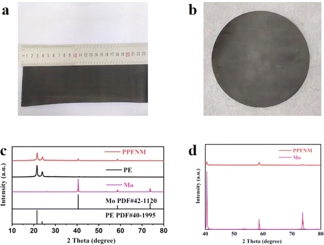
Fig. 1(a and b) displays optical photographs of a PPFNM separator, revealing a flat and uniformly grey surface. This straightforward and scalable process for preparing modified separators is advantageous for the widespread adoption of PPFNM separators in protecting lithium metal anodes. Fig. 1(c) presents the XRD pattern of the sample. The XRD pattern analysis of Mo yields an average grain size of 63 nm using Jade software. Notably, the XRD pattern of the PPFNM separator exhibits a sharp and intense diffraction peak separator that aligns perfectly with the characteristic peak of the PE separator (PDF#40–1995). Additionally, the XRD pattern of the PPFNM separator shows a distinct diffraction peak of Mo, which corresponds well with the characteristic peak of Mo (PDF#42–1120). Fig. 1(d) provides a clearer depiction of the perfect agreement between the diffraction peaks of Mo in the PPFNM separator and its characteristic peaks, confirming the presence of molybdenum nanopowder in the PPFNM separator.The investigation of the PPFNM separator's specific surface area and pore size distribution separator involved nitrogen adsorption isotherm experiments. The results, depicted in Fig. S1,† indicate that the PPFNM separator exhibits a narrow distribution of micro-pore sizes, approximately ranging from 20 to 50 nm. The specific surface area of the PPFNM separator measures 70.3 m2 g−1. The significant specific surface area of the PPFNM separator contributes to the achievement of uniform lithium deposition. Furthermore, the appropriate pore size facilitates electrolyte penetration and ensures favorable ion conductivity with in the modified separator.
Fig. 2(a and b) presents the SEM images of the PE separator and PPFNM separator, respectively. Currently, microporous PE separators are extensively utilized in the field of lithium-ion batteries. As depicted in Fig. 2(a), the pristine PE separator exhibits a typical dendritic porous structure. In contrast, Fig. 2(b) reveals that the PPFNM separator displays a distinct coating composed of densely packed molybdenum nanopowder particles, which contributes to an improved porous structure compared to the pristine PE separator. The thickness of the PPFNM coating, as observed in Fig. 2(c), measures approximately 10 μm. Fig. 2(d) illustrates the distribution of Mo elements within the PPFNM separator, demonstrating the uniform dispersion of molybdenum nanopowder across the separator.
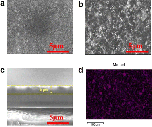 | ||
| Fig. 2 (a) Planar SEM image of PE separator, (b and c) cross-sectional SEM image of PPFNM separator, (d) distribution of Mo elements in PPFNM separators. | ||
Effect of PPFNM separators on the deposition/exfoliation behaviour of lithium metal anodes
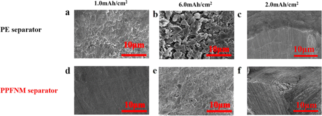
To investigate the impact of the PPFNM separator on the deposition and stripping behavior of the lithium metal negative electrode, Li–Li cell pairs were assembled. Lithium metal electrodes with capacities of 1.0 mA h cm−2 and 6.0 mA h cm−2 were deposited onto the lithium electrode sheets at a current density of 2.0 mA cm−2. In Fig. 3(a), it is evident that severe lithium dendrite growth and the formation of porous thick lithium layers, leading to uncontrolled dendrite formation, were observed when using PE separators after 1.0 mA h cm−2 deposition. However, in Fig. 3(d), separator the lithium electrode employing the PPFNM separator exhibited a smooth and dense structure free from dendrites. This indicates the beneficial influence of the molybdenum powder, guiding the uniform deposition of lithium ions. Furthermore, Fig. 3(e) demonstrates that with the PPFNM separator, the lithium electrode maintained a relatively smooth structure without any “dead lithium” on the surface even after 6.0 mA h cm−2 deposition. In contrast, Fig. 3(b) shows that the PE separator resulted in more “dead lithium” particles adhering to the surface, leading to irreversible capacity loss.19–21To further analyze the deposition, Fig. 3(c and f) presents SEM images of the cross-section of lithium deposited at a current density of 2.0 mA cm−2, reaching a capacity of 6.0 mA h cm−2 for each separator. In Fig. 3(f), it is noticeable that the lithium deposited on the lithium electrode sheet separator with the PPFNM separator exhibited greater density and more uniform thickness separator compared to the original separator. This comparison highlights the capability of the PPFNM separator, modified with nano-molybdenum powder, to induce uniform lithium deposition growth while reducing the volume change of the lithium metal anode during continuous cycling, thus, promoting stability and safety of the lithium metal anode.
Effect of PPFNM separator on the performance of Li–Li pairs of batteries
To assess the electrochemical stability of lithium metal electrodes utilizing PPFNM separators, Li–Li symmetric cells were assembled with both PE separators and PPFNM separators for electrochemical testing. The charge and discharge curves of Li–Li symmetric cells, with a capacity of 1.0 mA h cm−2, were examined at three different current densities of 0.6, 1.0, and 2.0 mA cm−2, as illustrated in Fig. 4. Fig. 4(a) illustrates the charge/discharge curves of Li–Li cell pairs with PE separators at various current densities. The results reveal a significant increase in polarization voltage with rising current density. Moreover, the charge/discharge curves exhibit considerable fluctuations, indicating non-uniform deposition of Li+ ions when employing PE separators. In contrast, Fig. 4(b) demonstrates that the polarization voltage of the charge/discharge curve for Li–Li cells utilizing PPFNM separators shows relatively minor variations with increasing current density, and the charge/discharge curve displays overall smoothness. These improvements can be attributed to the capability of the nano-molybdenum powder to facilitate uniform lithium deposition, while the modification of the separator with nano-molybdenum powder separator proves effective in reducing local current density.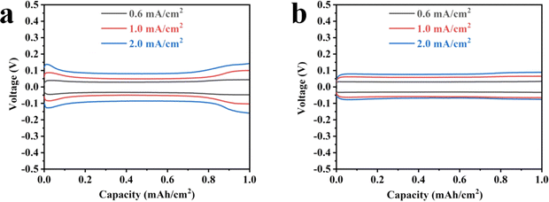 | ||
| Fig. 4 Charge and discharge curves of Li–Li symmetric cells using PE separator (a) and PPFNM separator (b). | ||
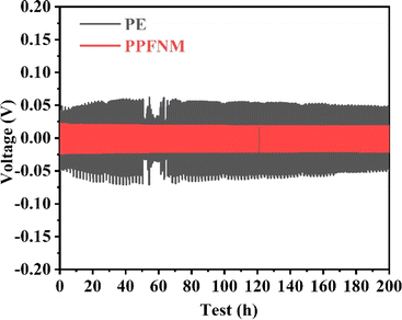
The voltage–time curve provides a clear indication of the cycle stability of the battery separator. To compare the effects of PE and PPFNM separators on battery performance and assess cycle stability, Li–Li symmetric batteries were assembled as a control group. Fig. 5 present the voltage distribution curves for Li–Li symmetric cells using PE and PPFNM separators under extended cycling conditions. In the case of a current density of 0.5 mA cm−2 and a capacity of 1 mA h cm−2, the Li–Li symmetric cell employing the PPFNM separator demonstrates stable behavior over 200 cycles, maintaining a consistent overpotential of approximately 21 mV. Conversely, the Li–Li symmetric cell with the PE separator exhibits significant voltage fluctuations at the beginning of the cycle,19–23 indicating non-uniform lithium metal deposition during initial cycles. Additionally, as the cycles progress, the overpotential of the Li–Li symmetric cell with the PE separator displays an upward trend, suggesting the formation of lithium dendrites and the presence of dead lithium.
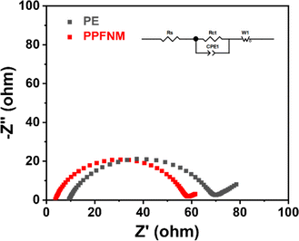
The electrochemical impedance spectra (EIS) were conducted on Li–Li symmetric cells employing PE separators and PPFNM separators at room temperature, ranging from 100 kHz to 1 Hz with an AC amplitude of 10 mV. The results are presented in Fig. 6. All the curves are constituted by the high frequency semicircles and the low-frequency sloped line, which corresponds to charge-transfer resistance (Rct) and lithium diffusion impedance, respectively.24 Upon observation of the figures, it is evident that the impedance of the Li–Li symmetric cell with the PE separator, prior to cycling, measured 61.06 Ω, whereas the impedance of the Li–Li symmetric cell with the PPFNM separator was only 55.32 Ω. These experimental separator findings indicate a significant improvement in the interfacial impedance of the Li–Li symmetric cell when utilizing the PPFNM separator. As we all know, high Li+ transference number and ionic conductivity are in favor of the low resistance, it is beneficial to the addition of PVDF-HFP on the separator, therefore, the EIS test can also demonstrate the elevated electrochemical performances of the PPFNM separator.25,26
To visualize the impact of the modified separator on the morphological state of the lithium metal electrode surface after cycling, SEM observations were conducted on Li–Li symmetric cells equipped with PE and PPFNM separators. The cells were examined after 70 cycles, with a current density of 2.0 mA cm−2 and a capacity of 2.0 mA h cm−2. The results are depicted in Fig. 7. Fig. 7(b) reveals that in the Li–Li symmetric cell utilizing the PPFNM separator, the lithium metal electrode sheet maintains a smooth and dense morphology, with no generation of lithium dendrites or dead lithium observed. In contrast, separator Fig. 7(a) illustrates a significant accumulation of lithium dendrites and dead lithium on the lithium metal surface when employing the PE separator. These observed outcomes, combined with the aforementioned electrochemical data for Li–Li symmetric cells, provide conclusive evidence that the use of nano-Mo powder-modified separators can effectively enhance the efficiency, cycling stability, and safety of Li-metal batteries.
 | ||
| Fig. 7 Li–Li symmetric cell using PE separator (a) and PPFNM separator (b) at 2.0 mA cm−2, 2.0 mA h cm−2, SEM image of a lithium electrode sheet after 70 cycles. | ||
Effect of PPFNM separator on the performance of Li–S batteries
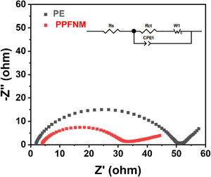
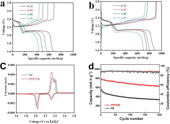
Building upon these discoveries, an in-depth examination of the electrochemical performance of the Li–S battery was conducted to further investigate the impact of utilizing the PPFNM separator. Fig. 8 displays the EIS plots of Li–S cells with both PE and PPFNM separators. The data clearly demonstrate that the charge transfer impedance (Rct),27 represented by the size of the high-frequency semicircle in the Nyquist plot, is smaller for the Li–S cell employing the PPFNM separator compared to the Rct of the Li–S cell using the original PE separator. This signifies an enhanced charge transfer performance, benefiting from a single-lithium-ion conductive nature of PVDF-HFP.Fig. 9(c) illustrates the CV curves for the initial cycle of Li–S cells employing both PE and PPFNM separators, showcasing the characteristic redox behavior of the Li–S cell. From the figure, it is evident that the peak areas of the oxidation and reduction peaks in the CV curves are larger for the cell with the PPFNM separator compared to the cell with the PE separator. Moreover, the peak areas of the PPFNM separator cell are separator substantially greater, indicating that the PPFNM separator effectively enhances the reaction kinetics of the cell. Additionally, the potential difference between the oxidation and reduction peaks is significantly reduced for cells with PPFNM separators, suggesting a decrease in cell polarization and promoting improved cycling stability.
To further investigate the impact of the PPFNM separator on Li–S cell performance, charge and discharge tests were conducted, as depicted in Fig. 9(a and b). The results reveal that at a rate of 0.2C, the Li–S battery with the PE separator achieved a discharge capacity of 667 mA h g−1, while the Li–S battery with the PPFNM separator reached a higher discharge capacity of 883 mA h g−1. The PPFNM separator clearly demonstrated a substantial advantage in terms of discharge capacity compared to the PE separator. Moreover, at a higher rate of 2.0C, the Li–S cell with the PE separator exhibited a discharge capacity of 436 mA h g−1, whereas the Li–S cell with the PPFNM separator achieved a higher discharge capacity of 703 mA h g−1. This highlights the clear advantage of the PPFNM separator in terms of discharge capacity as the current density is gradually increased. These results demonstrate that Li–S batteries can attain significantly enhanced capacity and rate performance through the use of PPFNM separators modified with Mo nanopowder.
Fig. 9(d) presents the cycling curves of Li–S batteries utilizing PE and PPFNM separators at a rate of 0.5C. The graph clearly illustrates that after 200 cycles, the Li–S cell employing the PPFNM separator exhibits a remarkable reversible capacity of 617 mA h g−1, with a capacity retention of 76.9%. This performance surpasses the 54.4% capacity retention achieved by the Li–S cell using the original PE separator. Following a specific duration of cycling, the capacity attenuation slows down. The exceptional cycling stability observed in the cells utilizing PPFNM separators can be attributed to the introduction of molybdenum powder, which facilitates the uniform deposition of lithium ions and significantly enhances cycle reversibility. These results firmly establish the viability of employing PPFNM separators, showcasing their clear advantages in improving the electrochemical performance of Li–S cells. Moreover, these findings highlight the effectiveness of PPFNM separators modified with nano-Mo powder in achieving stable and efficient LMBs.
Fig. S2† displays a scan of Mo powder, revealing near-spherical molybdenum particles on the Mo coating surface after cycling. These particles are significantly smaller than lithium sulfide particles, emphasizing the crucial role of Mo clusters in promoting the uniform deposition of discharge products. This uniform deposition is essential for facilitating efficient transport of electrons and ions at the electrode/electrolyte interface.
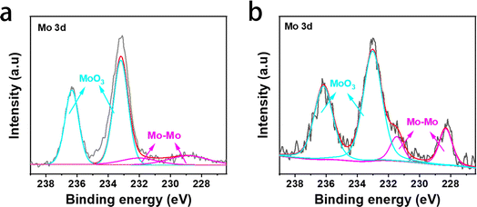
Fig. 10 shows the XPS spectra of Mo 3d and Li 1s (Fig. S3†) of the PPFNM separator before and after cycling. It can be observed from the XPS spectrum of Mo 3d that there are characteristic peaks of MoO3 in the high-resolution Mo 3d XPS spectrum before cycling (see Fig. 10(a)), which are located at 236.3 eV (3/2d) and 233.2 eV (5/2d) respectively,28,29 which are caused by slow oxidation in air. The peaks of 232.0 eV and 228.9 eV correspond to the Mo–Mo bond.30–33 After the cycle, the characteristic peak of MoO3 showed a significant shift, which we believe may be caused by the reaction of MoO3 with lithium metal. In addition, the surface structure did not change significantly, which indicates that the modified PPFNM diaphragm has good stability. The signal intensity of the Li 1s peak after the cycle is very high, indicating that Mo powder has a strong lithium affinity. This finding proves that lithium batteries assembled using PPFNM membranes have a protective effect on the negative electrode.
Furthermore, the diaphragm plays a crucial role in ion conduction on both sides, and its excellent electrolyte wettability reduces the contact angle between the electrode and the diaphragm. As depicted in Fig. S4(a),† adding a drop of electrolyte to the pure PP diaphragm results in a large arc (38.46°) on the diaphragm's surface. In contrast, Fig. S4(b)† shows that the arc immediately disappears (13.34°) after adding the electrolyte drop to the PPFNM-based diaphragm. This comparison underscores the excellent electrolyte storage performance of the PPFNM-based diaphragm, likely attributed to the introduction of Mo material, which enhances electrolyte infiltration. In summary, the reduced contact angle facilitates ion transport, ultimately improving battery performance.
Conclusion
Separators comprised of PPFNM separator were fabricated utilizing a straightforward method, which involved coating the surface of PE separators with a protective layer of nano-Mo powder. This powder is renowned for its superior electrochemical properties and pro-lithium characteristics. The optimal production process was determined via meticulous process optimization. The investigation of the electrochemical performance of the constructed Li–Li symmetric cells, as well as Li–S cells, was carried out through a combination of physical and electrochemical characterization methods. From this research, several conclusions were drawn. Li-metal symmetric cells equipped with PPFNM separators demonstrated a stable performance over 200 cycles, maintaining an overpotential at an approximate value of 21 mV. Examination of the surface morphology of the Li-metal electrodes from cells utilizing PPFNM separators revealed a considerably smoother surface. Additionally, a noteworthy reversible capacity of 617 mA h g−1 was recorded after 200 cycles at a rate of 0.5C. The Li–S cell incorporating the PPFNM separator maintained a capacity retention of 76.9%. These findings strongly suggest that PPFNM separators, when modified with nano-Mo powder, exhibit significant potential in protecting the lithium metal anode and in enhancing overall battery performance.Data availability
All data generated and analyzed during this study are included in this article.Author contributions
Lei Li: conceptualization, methodology, software; Yu Wu: data curation, writing – original draft preparation. Chunhong Hu: visualization, investigation; Juanjuan Li: supervision; Xin Guo: software, validation; Lei Li and Xin Guo: writing – reviewing and editing. All authors read and approved the final manuscript.Conflicts of interest
The author(s) declare(s) that there is no conflict of interest.Acknowledgements
This work was supported by the Air Force Aviation University.References
- Q. Lu, Y. Jie, X. Meng, A. Omar, D. Mikhailova, R. Cao, S. Jiao, Y. Lu and Y. Xu, Carbon Energy, 2021, 3, 957–975 CrossRef CAS.
- X. Sun, S. Liu, W. Sun and C. Zheng, Chin. Chem. Lett., 2023, 34, 107501 CrossRef CAS.
- P. Zuo, J. Hua, M. He, H. Zhang, Z. Qian, Y. Ma, C. Du, X. Cheng, Y. Gao and G. Yin, J. Mater. Chem. A, 2017, 5, 10936–10945 RSC.
- L. Nie, Y. Li, S. Chen, K. Li, Y. Huang, Y. Zhu, Z. Sun, J. Zhang, Y. He, M. Cui, S. Wei, F. Qiu, C. Zhong and W. Liu, ACS Appl. Mater. Interfaces, 2019, 11, 32373–32380 CrossRef.
- C. Niu, H. Pan, W. Xu, J. Xiao, J. G. Zhang, L. Luo, C. Wang, D. Mei, J. Meng, X. Wang, Z. Liu, L. Mai and J. Liu, Nat. Nanotechnol., 2019, 14, 594–601 CrossRef.
- G. Xu, Q. B. Yan, S. Wang, A. Kushima, P. Bai, K. Liu, X. Zhang, Z. Tang and J. Li, Chem. Sci., 2017, 8, 6619–6625 RSC.
- X. Li, Y. Liu, Y. Pan, M. Wang, J. Chen, H. Xu, Y. Huang, W. M. Lau, A. Shan, J. Zheng and D. Mitlin, J. Mater. Chem. A, 2019, 7, 21349–21361 RSC.
- M. Liu, N. Deng, J. Ju, L. Wang, G. Wang, Y. Ma, W. Kang and J. Yan, ACS Appl. Mater. Interfaces, 2019, 11, 17843–17852 CrossRef CAS.
- Q. Wang, B. Liu, Y. Shen, J. Wu, Z. Zhao, C. Zhong and W. Hu, Adv. Sci., 2021, 8, 2101111 CrossRef CAS PubMed.
- Z. Shadike, S. Tan, R. Lin, X. Cao, E. Hu and X. Q. Yang, Chem. Sci., 2022, 13, 1547–1568 RSC.
- C. Li, S. Liu, C. Shi, G. Liang, Z. Lu, R. Fu and D. Wu, Nat. Commun., 2019, 10, 1363 CrossRef.
- J. Liu, J. Zhang, J. Zhu, R. Zhao, Y. Zhang, Y. Ma, C. Li, H. Zhang and Y. Chen, Nano Res., 2023, 16, 12601–12607 CrossRef CAS.
- B. Ma, Y. Gao, M. Niu, M. Luo, H. Li, Y. Bai and K. Sun, Solid State Ionics, 2021, 371, 115750 CrossRef CAS.
- R. Saroha, J. Heo, X. Li, N. Angulakshmi, Y. Lee, H.-J. Ahn, J.-H. Ahn and J.-H. Kim, J. Alloys Compd., 2022, 893 Search PubMed.
- W. Fan, L. Zhang and T. Liu, Mater. Chem. Front., 2018, 2, 235–252 RSC.
- H. Dai, L. Wang, Y. Zhao, J. Xue, R. Zhou, C. Yu, J. An, J. Zhou, Q. Chen, G. Sun and W. Huang, Research, 2021, 2021, 5130420 CrossRef PubMed.
- L. Wang, Q. Zhang, J. Zhu, X. Duan, Z. Xu, Y. Liu, H. Yang and B. Lu, Energy Storage Mater., 2019, 16, 37–45 CrossRef.
- M. S. Freitag and L. Ionov, J. Power Sources, 2017, 363, 384–391 CrossRef.
- S. Ponnada, M. S. Kiai, D. B. Gorle, S. Rajagopal, S. Andra, A. Nowduri and K. Muniasamy, Energy Fuels, 2021, 35, 11089–11117 CrossRef CAS.
- C. Yu, K. Park, J.-H. Jang and J. B. Goodenough, ACS Energy Lett., 2016, 1, 633–637 CrossRef.
- J. Wang, S. Yi, J. Liu, S. Sun, Y. Liu, D. Yang, K. Xi, G. Gao, A. Abdelkader, W. Yan, S. Ding and R. V. Kumar, ACS Nano, 2020, 14, 9819–9831 CrossRef CAS.
- A. Kim, S. H. Oh, A. Adhikari, B. R. Sathe, S. Kumar and R. Patel, J. Mater. Chem. A, 2023, 11, 7833–7866 RSC.
- Y. Zhao, Z. Gu, W. Weng, D. Zhou, Z. Liu, W. Fan, S. Deng, H. He and X. Yao, Chin. Chem. Lett., 2023, 34, 107232 CrossRef.
- X. Liu, J. Liu, B. Lin, F. Chu and Y. Ren, ACS Appl. Energy Mater., 2021, 5, 1031–1040 CrossRef.
- X. Hao, H. Wenren, X. Wang, X. Xia and J. Tu, J. Colloid Interface Sci., 2020, 558, 145–154 CrossRef.
- A. Zhang, X. Fang, C. Shen, Y. Liu, I. G. Seo, Y. Ma, L. Chen, P. Cottingham and C. Zhou, Nano Res., 2018, 11, 3340–3352 CrossRef CAS.
- J. Liu, J. Wang, L. Zhu, X. Chen, G. Yi, Q. Ma, S. Sun, N. Wang, X. Cui, Q. Chai, J. Feng and W. Yan, J. Mater. Chem. A, 2022, 10, 14098–14110 RSC.
- C. Yang, X. Zhong, Y. Jiang and Y. Yu, Chin. Chem. Lett., 2017, 28, 2231–2234 CrossRef CAS.
- S. Imtiaz, Z. Ali Zafar, R. Razaq, D. Sun, Y. Xin, Q. Li, Z. Zhang, L. Zheng, Y. Huang and J. A. Anderson, Adv. Mater. Interfaces, 2018, 5, 1800243 CrossRef.
- X.-T. Hu, J.-G. Qian, Y. Yin, X. Li, T.-J. Li and J. Li, Rare Metals, 2018, 42, 2439–2446 CrossRef.
- Z. Jiang, W. Huang, Z. Zhang, H. Zhao, D. Tan and X. Bao, J. Phys. Chem. B, 2006, 110, 26105–26113 CrossRef PubMed.
- Z. Jiang, W. Huang, Z. Zhang, H. Zhao, D. Tan and X. Bao, Chem. Phys. Lett., 2007, 439, 313–317 CrossRef.
- J. Zhang, Y. Wang, Z. Zhou, Q. Chen and Y. Tang, Materials, 2023, 16, 1635 CrossRef PubMed.
Footnote |
| † Electronic supplementary information (ESI) available. See DOI: https://doi.org/10.1039/d4ra05371k |
| This journal is © The Royal Society of Chemistry 2024 |

