 Open Access Article
Influence of deposition conditions on performance of Ni3S2 as the bifunctional electrocatalyst in alkaline solutions by galvanostatic deposition
Minjie Zhu*a,
Min Liub and
Jing Zhangc
aState Grid Zhejiang Electric Power Company, Taizhou Power Supply Company, TaiZhou, 318000, China
bState Grid Zhejiang Electric Power Co., Ltd, Electric Power Science Research Institute, Hangzhou, 310014, China
cTongji University, 4800 Cao'an Road, Shanghai, 201804, China
First published on 18th September 2024
Abstract
The electrodeposition method is a popular synthesis method due to its low cost, simplicity, and short synthesis time. In addition, this synthesis route results in the preparation of a self-supporting electrocatalyst, which eliminates the use of binders and ultimately facilitates the durability as well as the activity of the catalyst. In this work, a series of Ni3S2/Ni mesh electrodes are prepared by galvanostatic deposition at different deposition current densities and times. The morphology, microstructure, and elemental composition distribution of these obtained electrodes are characterized, and the hydrogen evolution reaction (HER) and oxygen evolution reaction (OER) performance of the series of Ni3S2/Ni meshes are tested. The results show that the Ni3S2/Ni mesh electrodes electrodeposited at 30 mA cm−2 for 1200 s have superior electrochemical performance for HER and OER. The overpotentials of Ni3S2/Ni mesh 30 mA cm−2–1200 s are 236 and 244 mV for HER and OER, respectively, at a current density of 10 mA cm−2. In addition, the Tafel slopes for HER and OER are 113 mV dec−1 and 176 mV dec−1, respectively. This research provides some valuable insights into the use of the electrodeposition method for the fabrication of electrocatalysts.
1. Introduction
The global energy crisis and greenhouse gas emissions have resulted in significant impacts, including climate changes and rising sea levels.1–4 Therefore, it is crucial to conduct research on renewable energy as a matter of urgency.5,6 Hydrogen is a promising secondary energy source with a high calorific value in new energy systems.7,8 It can be stored as a gas or liquid under high pressure in tanks or reversibly absorbed and released by solid hydrogen storage materials.9 In addition, hydrogen has a strong potential for grid applications.10 Renewable energy sources, including wind and solar photovoltaic, have seasonal, intermittent, and regional limitations. To optimize energy storage and transportation, such sources can be converted into hydrogen energy.8,11,12Hydrogen has recently been widely considered as a potential renewable energy source. However, the majority of hydrogen is currently produced from natural gas and coal, which are fossil fuels.13–15 To fulfill the Paris Agreement's objective, hydrogen production must transition effectively from a traditional fossil fuel-based approach to one that employs renewable sources.16 In this context, electrolytic hydrogen production from renewable energy sources is highly anticipated due to its eco-friendliness, abundant water resources, and high hydrogen purity (≈99.999%).17,18 Additionally, it can integrate other renewable energy sources into the grid and create a significant downstream market.19 Depending on the electrolytes and operating temperatures involved, water electrolysis technology can be classified into four categories: alkaline water electrolysis, proton exchange membrane water electrolysis, anion exchange membrane water electrolysis, and solid oxide water electrolysis.20 Among these, alkaline water electrolysis is known to be the optimal choice for large-scale hydrogen synthesis due to the utilization of non-precious metal catalysts.21 This technology is widely accepted by suppliers as the most commercially viable and applicable process.22
The process of water electrolysis includes two sluggish half-reactions, namely hydrogen evolution reaction (HER) and oxygen evolution reaction (OER).23–25 In acidic media, precious-metal-based materials, such as Pt for HER and Ir/Ru compounds for OER, are typically employed as electrocatalysts to enhance slow electrochemical activity.26 However, the use of scarce and expensive catalysts is not preferred as it significantly raises the cost of hydrogen production and impedes growth.27–29 Non-precious metal electrocatalysts comprising alloys, oxides, hydroxides, sulfides, carbides, nitrides, and other materials are presently undergoing rapid development.30–32 Among them, nickel sulfides are excellent options for OER and HER electrocatalysts,33–40 and Ni3S2 is theoretically considered to be an excellent dual-function electrocatalyst because Ni3S2 not only promotes H2 production in HER but also promotes OOHads formation in OER.41,42 On the one hand, multiple valence states of Ni existing in Ni3S2 could promote the adsorption and dissociation of water on the surface to generate the intermediate (OOH*), which is favorable for OER.43 In addition, due to the higher nickel content, Ni3S2 surfaces are easily coated with nickel (oxygen) hydroxides with catalytic activity, thus improving the OER performance.44 On the other hand, the Ni–S bond has a strong chemisorption capability for hydrogen due to the small free energy, which is beneficial for HER.45 Furthermore, the modulation of the surface atomic configuration of Ni3S2 is convenient for balancing the absorption/desorption of the targeted intermediates (OH− and H*), thereby improving the kinetics of HER.46,47 Experimental and theoretical calculations have attributed the good catalytic performance of Ni3S2 to its inherent metal conductivity, numerous active sites, and suitable Gibbs free energy of the catalytic site.26,42 The low cost, abundant resources, easy preparation, and excellent catalytic activity make Ni3S2 popular in non-precious metal electrocatalysts.48 In recent years, Ni3S2 has garnered significant attention as an economical and high-activity catalyst for alkaline water electrolysis.41,49 DFT calculations suggest that the primary interaction and contribution of Ni3S2 is attributed to the d-orbital of Ni, with the s-orbital of S playing a minor role.50 Ni3S2 displays metallic properties as most of its orbitals cross the Fermi level. Foam nickel and nickel mesh are commonly utilized as electrode substrates in research, as well as in industrial electrolysis procedures for large-scale hydrogen generation. Ni3S2 catalyst was prepared by high current density deposition and in situ vulcanization, resulting in a highly exposed active site and a unique 3D heterogeneous interface.51 This paper specifically centers on the Ni3S2 material for the creation of high-performance Ni3S2 electrocatalysts that can be used in alkaline water electrolysis based on these advantages.
The hydrothermal and electrodeposition methods are widely accepted techniques for preparation due to their low cost, simple synthesis process, and wide range of applications.52,53 These methods can produce electrocatalysts with high purity, good crystallinity, and regular morphology.54 The core of the hydrothermal method is to select appropriate precursors and reaction conditions. The electrodeposition method employs electricity to facilitate the deposition process of the catalyst on the substrate, making it ideal for creating self-supporting electrodes.55 This method can synthesize various products through the regulation of the precursor solution, deposition time, and deposition current density.52,56–58 As a result, the electrodeposition method has broad applications in developing microstructured electrocatalysts based on non-precious metals.59,60 However, there is less discussion regarding the effect of electrodeposition condition parameters, such as deposition time and deposition current, on the catalysts' performance.
Depositing Ni3S2 on nickel mesh and foam nickel exhibits lower overpotential and better electrocatalytic performance.42 This study utilized an electrodeposition method based on nickel mesh and foam to prepare the Ni3S2/Ni mesh electrode. The impact of alterations to electrodeposition condition parameters on electrode morphology and catalytic performance was investigated by varying the deposition current density and deposition time. The electrodes' composition and morphology were analyzed using various methods, including scanning electron microscopy (SEM), Raman spectroscopy, transmission electron microscopy (TEM), X-ray diffraction patterns (XRD), and X-ray photoelectron spectroscopy (XPS). Additionally, cyclic voltammetry curves, polarization curves, and electrochemical impedance spectroscopy (EIS) were utilized to evaluate the impact of the synthesized electrodes on catalytic activity for HER and OER. First, this research combines the electrodeposition condition parameters with the electrodes' morphology and electrochemical performance to discuss the influence of electrodeposition condition parameters on Ni3S2/Ni mesh electrodes.
2. Results and discussion
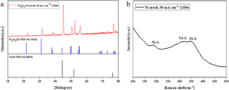
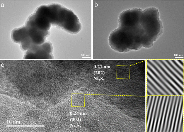
First, the in situ generation of Ni3S2 electrocatalysts on Ni mesh was synthesized via electrodeposition for 1200 s under the current density of 30 mA cm−2. The sample of Ni3S2/Ni mesh 30 mA cm−2–1200 s was chosen to conduct the XRD, Raman, and XPS analysis. Fig. 1a shows the XRD pattern of the Ni3S2/Ni mesh sample. A series of XRD diffraction peaks at 2θ = 21.7°, 31.1°, 37.8°, 38.2°, 44.3°, 50.1°, and 55.1° are attributed to the (101), (110), (003), (021), (202), (211), and (122) facets of the Ni3S2 crystal (JCPDS 44-1418),61 respectively. There are distinct diffraction peaks at 2θ = 44.8°, 52.0° and 76.4° from the Ni mesh matrix (JCPDS 04-0850).62 To verify the successful synthesis of Ni3S2/Ni mesh composites, the synthesized samples were further analyzed using Raman spectroscopy. As shown in Fig. 1b, the Raman shifts at 206, 302, and 352 cm−1 are consistent with the Ni–S bond of Ni3S2, strongly confirming the formation of Ni3S2/Ni mesh.63–65To investigate the structure and morphology of the Ni3S2/Ni mesh in detail, the electrode material was carefully peeled off the Ni mesh for TEM analysis. The results showed clusters of Ni3S2 of different sizes, as shown in Fig. 2a, with a diameter of about 200 nm and, in Fig. 2b, with a diameter of about 100 nm each. HRTEM images of Ni3S2 are shown in Fig. 3c. The lattice stripe spacing of 0.21 nm observed on the nanosheets indicates the presence of the (202) crystal plane of Ni3S2. Similarly, the lattice stripe spacing of 0.24 nm corresponds to the (003) crystal plane of Ni3S2. The TEM and HRTEM images are in agreement with the XRD and Raman results.
 | ||
| Fig. 3 XPS survey spectra for Ni3S2/Ni mesh 30 mA cm−2–1200 s (a); XPS results of different elements. (b) Ni 2p and (c) S 2p. | ||
The surface composition and valence state of the Ni3S2/Ni mesh 30 mA cm−2–1200 s (hereinafter referred to as Ni3S2/Ni 3–12) crystal structure were measured by X-ray photoelectron spectroscopy (XPS). The survey spectra Fig. 3a of the Ni3S2/Ni 3–12 show the peaks of Ni and S with unexpected signals of C and O elements due to the contamination/surface oxidation of the product. In the Ni 2p spectrum (Fig. 3b), the two main peaks at 855.5 eV and 873.6 eV, with two satellite peaks at 861.9 and 879.7 eV, could be attributed to Ni 2p3/2 and Ni 2p1/2 from Ni3S2.66,67 The two peaks at 855.5 eV and 873.6 eV represent Ni+ and Ni2+ respectively. In the S 2p spectrum (Fig. 3c), there are two peaks at 161.6 eV and 163.0 eV corresponding to S 2p3/2 and S 2p1/2 of S, respectively, while the peak at 168.3 eV indicates a partial oxidation state of the S element on the sample surface.68
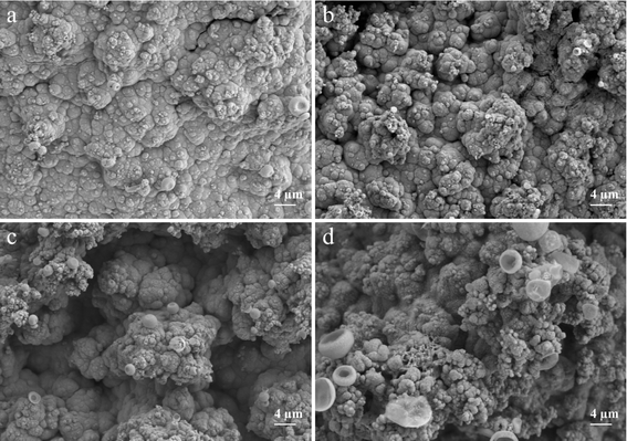
To examine how diverse electrodeposition current densities impact electrode morphology, Ni3S2/Ni mesh electrodes were electrodeposited at the current densities of 20, 30, 40, and 50 mA cm−2 for 1200 s, respectively. Fig. 4 displays SEM images of the synthesized electrodes at different deposition current densities. As shown in Fig. 4, the electrodeposition current density increased from 20 mA cm−2 to 50 mA cm−2, resulting in a gradual increase in Ni3S2 deposition on the Ni mesh. Ni3S2 was observed to exist in the form of clusters on the Ni mesh, which is in agreement with the TEM observations. As the deposition current density increased, the clusters' growth sites gradually expanded, resulting in denser clusters on the electrode surface. This can increase the electrode's active substance loading to some degree, thereby improving its catalytic performance.57,69 However, an excessive number of growth sites results in the dense dispersion of active substances on the substrate. These substances tend to accumulate upwards, perpendicular to the electrode surface. Fig. 4 provides a clearer visualization of this phenomenon. Increasing the current density to 40 mA cm−2 shows that Ni3S2 exhibits a distinct forest-like growth pattern on the Ni mesh. The dense, forest-like morphology may hinder the improvement of the electrode's electric active surface area and the rapid release of gas bubbles. Additionally, it may degrade the electrode performance, which is in line with the subsequent electrochemical test results.70
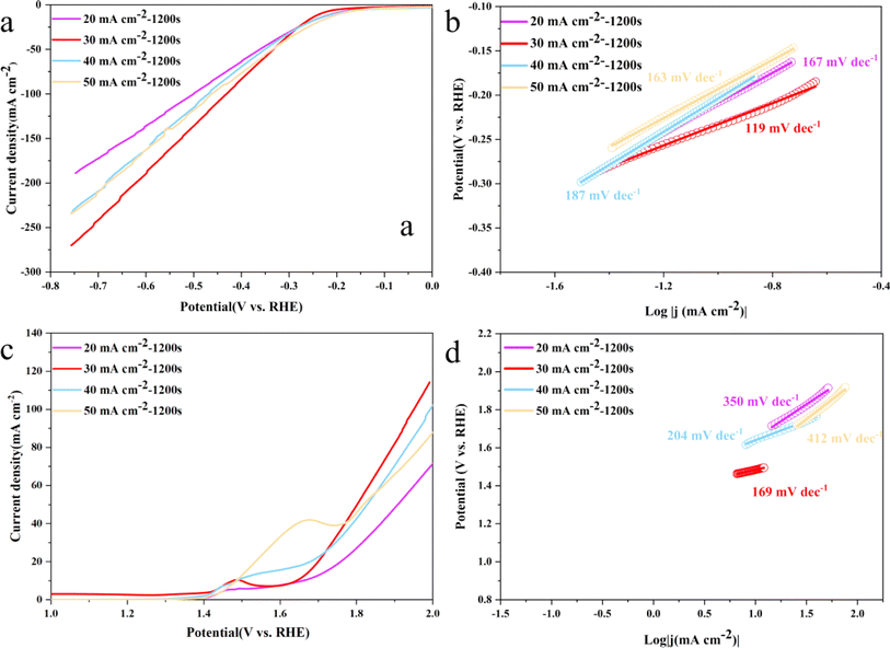
The electrocatalytic activity of Ni3S2/Ni mesh electrodes synthesized at various current densities was experimentally examined at ambient temperature. The LSV and Tafel slope curves of Ni3S2/Ni mesh electrodes for HER and OER are presented in Fig. 5. The Ni3S2/Ni mesh electrodes, synthesized through deposition at a current density of 30 mA cm−2, displayed a lower overpotential for both HER and OER when contrasted with electrodes synthesized at other current densities. Their overpotentials at a current density of 10 mA cm−2 were 230 and 245 mV for HER and OER, respectively. As for the HER catalyst, the overpotentials of Ni3S2/Ni mesh 30 mA cm−2–1200 s were 268, 333, and 430 mV at 20, 50, and 100 mA cm−2. For the OER, the overpotentials of Ni3S2/Ni 3–12 were 470 mV, 572 mV, and 691 mV at 20 mA cm−2, 50 mA cm−2, and 100 mA cm−2, respectively. Above 100 mA cm−2, Ni3S2/Ni 3–12 demonstrated a lower HER and OER overpotential. In particular, the Tafel slopes of 119 mV dec−1 and 121 mV dec−1 for HER and OER of Ni3S2/Ni 3–12 were lower than the electrodes synthesized at other current densities of the same series, presenting better reaction kinetics.
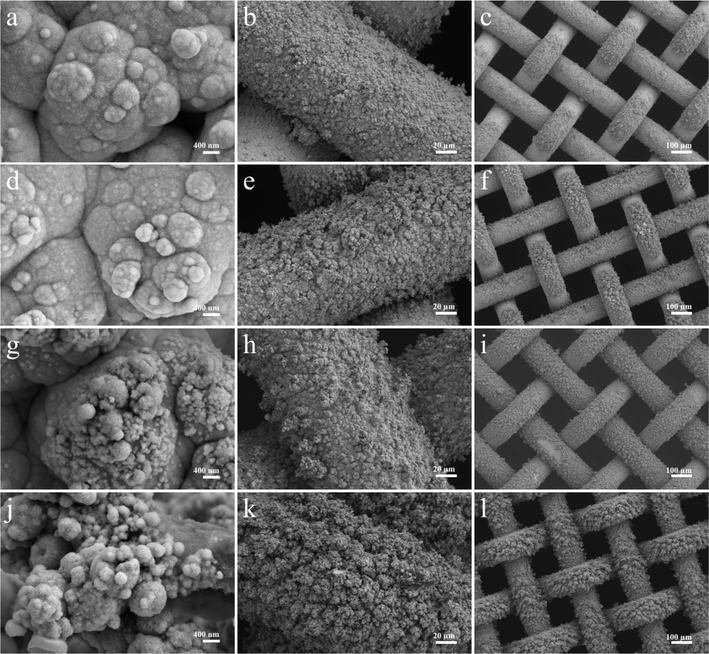
To investigate the effect of different deposition times on the catalytic performance of the electrodes, a series of Ni3S2/Ni mesh electrodes with different deposition times were further deposited at 30 mA cm−2 deposition current density for 300, 600, 1200, and 1800 s in the experiments. To investigate the effect of different electrodeposition times on the morphology of the electrodes, SEM tests were carried out on Ni3S2/Ni mesh electrodes deposited for 600, 900, 1200, and 1800 s in this experiment. Fig. 6 shows the SEM images of the electrodes with different deposition times. From the images, it can be seen that as the deposition time increases, the active materials deposited on the Ni mesh surface gradually increase and grow outward in a tree-like manner, the active material loading increases, and the size of the clusters tends to increase, and the pores between the clusters are further reduced. When the deposition time reached 1200 s, a forest-like morphology was formed on the substrate surface, and the catalytic performance was improved by more active substance loading. As the deposition time increases further, the active substance covering the substrate grows further. When the deposition time reaches 1800 s, the excessively deposited actives cause a decrease in the specific surface area, and the decrease in the gaps between the clusters also affects the rapid release of gas bubbles, which results in a decrease in the catalytic performance of the electrode, which is further verified by subsequent electrochemical performance tests.71
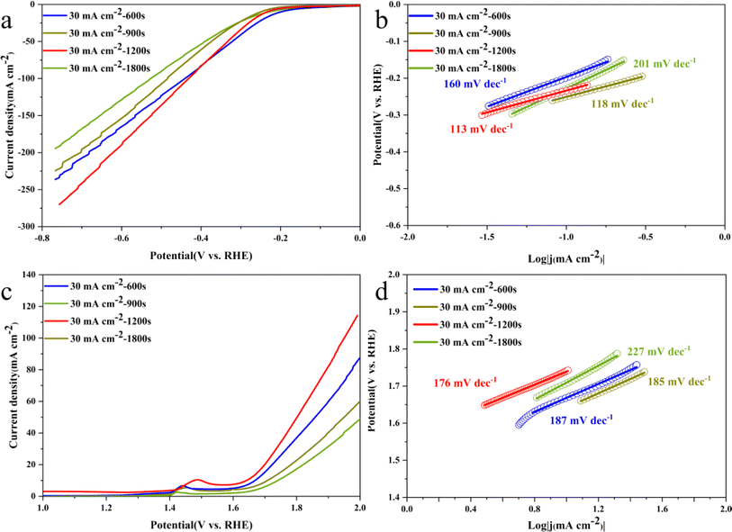
Fig. 7 shows the LSV and Tafel slope curves for HER and OER of Ni3S2/Ni mesh electrodes with different deposition times. The electrodes deposited for 1200 s for HER and OER show smaller overpotentials compared to the electrodes synthesized at other current densities. Their overpotentials are 236 and 244 mV for HER and OER, respectively, at a current density of 10 mA cm−2. For HER, the overpotentials of Ni3S2/Ni 3–12 electrocatalysts are 271, 332, and 433 mV at 20, 50, and 100 mA cm−2, respectively. For OER, the overpotentials of Ni3S2/Ni 3–12 electrocatalysts are 471 and 570 mV at 20 and 50 mA cm−2, respectively. The overpotential of the electrocatalyst is 471 and 570 mV at 20 and 50 mA cm−2, respectively. In the higher current region above 100 mA cm−2, Ni3S2/Ni 3–12 shows lower HER and OER overpotentials. In addition, the Tafel slopes of 113 mV dec−1 and 176 mV dec−1 for HER and OER, respectively, are in general agreement with the performance of Ni3S2/Ni 3–12 in Fig. 5b and d, showing good reaction kinetics. This suggests that the optimal performance is achieved by increasing the active substance loading at a deposition time of 1200 s without overdepositing to the extent that it adversely affects the contrasting surface area and the rapid release of gas bubbles.52,53 Despite its basis in a nickel mesh, the catalyst described in this paper demonstrates comparable performance to that of Ni3S2/NF as listed in Table 1.74 In addition, a comparison with the noble metal catalyst Pt/C and IrO2 is listed in Table 2.77 Compared to the noble metal catalyst, the HER performance of the Ni3S2 is weak, while the OER performance is good due to the higher nickel content.
| Catalyst | Water electrolysis test | Electrolyte | Overpotential [mV]@current density [mA cm−2] | Tafel slopes | Reference |
|---|---|---|---|---|---|
| Ni3S2/Ni 3–12 | HER | 1 M KOH | 236@10 | 113 mV dec−1 | This work |
| OER | 244@10 | 176 mV dec−1 | This work | ||
| Ni3S2/AT-Ni foam | HER | 1 M KOH | 200@10 | 107 mV dec−1 | 72 |
| OER | 217@10 | 163 mV dec−1 | 72 | ||
| Ni3S2–FeS–CoS/PNFCF | HER | 1 M KOH | 82@10 | 68 mV dec−1 | 73 |
| OER | 170@10 | 76 mV dec−1 | 73 | ||
| Ni(OH)2/Ni3S2 | HER | 1 M KOH | 50@10 | 49 mV dec−1 | 43 |
| OER | 210@10 | 72 mV dec−1 | 43 | ||
| Ni3S2/NF | HER | 1 M KOH | 223@10 | — | 74 |
| OER | 260@10 | — | 74 | ||
| Co–Ni3S2/NF | OER | 1 M KOH | 120@10 | 38.4 mV dec−1 | 75 |
| DSO-Ni3S2/NF | OER | 1 M KOH | 241@20 | 40 | 76 |
| Catalyst | Water electrolysis test | Electrolyte | Overpotential [mV]@current density [mA cm−2] | Tafel slopes | Reference |
|---|---|---|---|---|---|
| Pt/C | HER | 1 mol L−1 KOH | 25@10 | 42 mV dec−1 | 77 |
| IrO2 | OER | 360@10 | 139 mV dec−1 | 77 | |
| Ce–NiVS | HER | 1 M KOH and 0.5 M urea mixed alkaline solution | 141@10 | 114.67 mV dec−1 | 78 |
| CuO@NiCo LDH/CF | OER | 1 M KOH | 256@20 | 91 mV dec−1 | 79 |
| CuCo2O4 | HER | 1 M KOH and 0.5 M urea mixed alkaline solution | 176@10 | 85.56 mV dec−1 | 80 |
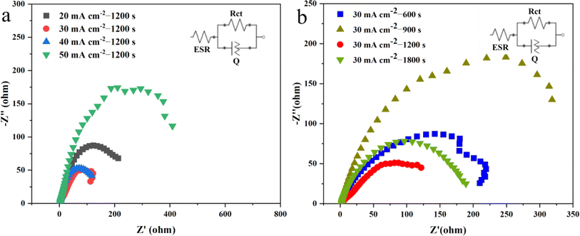
The electrochemical impedance spectra (EIS) in Fig. 8a demonstrate that the samples deposited at a current density of 30 mA cm−2 have a smaller charge transfer resistance. Fig. 8b displays the EIS results for electrodes prepared by depositing the sample at a current density of 30 mA cm−2 for different durations. And Table 3 show the EIS parameters of all samples. It indicates that the Ni3S2/Ni mesh electrodes deposited for 1200 s exhibit better charge transfer compared to the other electrodes. The improved performance of the Ni3S2/Ni 3–12 electrode could be attributed to the specific morphology of the catalyst layer. The forest-like morphology of the Ni3S2/Ni mesh created under these conditions leads to a moderate amount of active material loading, which could guarantee not only a high electrochemically active surface area of the Ni3S2 catalyst layer but also rapid bubble release. Therefore, the Ni3S2/Ni 3–12 is deemed optimal.57,81
| Samples | Rct (Ω)@ −0.2 V |
|---|---|
| Ni3S2/Ni 2–12 | 252 |
| Ni3S2/Ni 3–12 | 196.6 |
| Ni3S2/Ni 4–12 | 210.1 |
| Ni3S2/Ni 5–12 | 555 |
| Ni3S2/Ni 3–18 | 221.4 |
| Ni3S2/Ni 3–16 | 435.5 |
| Ni3S2/Ni 3–9 | 235.3 |
The electrocatalytic activity of Ni3S2/Ni mesh for OER and HER is dependent on active site exposure82 and fast gas diffusion.70,71,83 As the deposition current density increases while keeping the electrodeposition time constant, the growth sites of the clusters gradually expand. This, in turn, results in denser clusters on the electrode surface, leading to an increase in the electrode's active substance loading and, consequently, an improvement in its catalytic performance. However, an overabundance of growth sites leads to a crowded distribution of active substances on the substrate. At a right angle, these substances accumulate vertically to the electrode surface. The formation of a new layer not only envelops the pre-existing active sites but also elevates the impedance due to the creation of fresh crystal interfaces.84 In addition, the new formation layer suppresses the gas diffusion. The same is true when the deposition current density is fixed: as the deposition current density increases, the amount of active substance on the electrode surface and the active sites also increase. By increasing the deposition time to 1200 s, Ni3S2/Ni 3–12 demonstrated the greatest OER and HER properties. However, further increases in deposition time led to a decrease in electrode activity, likely caused by the formation of a new layer covering pre-existing active sites and suppressing gas diffusion, resulting in escalated impedance during electrodeposition.85 The electrochemical impedance spectra (EIS) results correspond with the kinetic parameters, including the Tafel slope curves and LSV curves.
3. Materials and methods
3.1. Catalyst fabrication
This study involves the pretreatment of commercial nickel mesh. Nickel mesh in 100 mesh size is supplied by Hebei Kangwei. Initially, the mesh was cut into a 1 cm × 2 cm square. Next, the nickel mesh underwent 20 min of sonication in acetone, followed by sonication for 10 min in a 1.0 M hydrochloric acid solution to eliminate the oxide layer present on the surface of the material. Finally, the nickel mesh was washed using deionized water and anhydrous ethanol and then dried under vacuum at 60 °C for one hour.In this experiment, after processing the nickel mesh, 0.1 M thiourea (H2NCSNH2) and 0.02 M nickel sulfate hexahydrate (Ni(NO3)2·6H2O) were placed in a beaker containing 60 mL of deionized water. The beaker was then placed in a heating jacket and the heating temperature was controlled at 70 °C until the drug was dissolved in the beaker and the solution appeared as a transparent dark green color. Then, the experiment was carried out using a CHI660E electrochemical workstation. The Ni mesh was the working electrode, and Pt foil was the counter electrode. The reference electrode was a saturated Ag/AgCl electrode. The electrodeposition was carried out on the pretreated Ni mesh using the prepared solution as an electrolyte. Finally, the Ni3S2/Ni mesh electrode was dried in a 60 °C oven for eight hours. In this experiment, the preparation of Ni3S2/Ni mesh electrodes was controlled by adjusting the current density and deposition time of electroplating. The electrodeposition current densities were 20, 30, 40, and 50 mA cm−2, and deposition times were 600, 900, 1200, and 1800 s. The electrodeposition current density and deposition time were adjusted to study the effect of different electroplating parameters on electrode morphology and catalytic performance. For convenience, they are referred to as Ni3S2/Ni mesh X mA cm−2-Y, where X is the plating current density, and Y is the deposition time.
3.2. Characterization
The composition and crystal structure of the prepared electrode were analyzed in this experiment using a Bruker D8 ADVANCE X-ray diffractometer produced in Germany. The diffractometer utilized Cu Kα radiation as the diffraction source, with a working voltage of 30 kV/40 mA, a testing angle range of 10°–90°, and a scanning speed of 5° min−1. In addition, the X-ray photoelectron spectroscopy (XPS) spectra were measured on an ESCALAB 250 Xi with Al Kα as the source. The electrode was deposited directly onto the substrate using the electrodeposition method. It was then cut into a square sample measuring 0.5 cm × 0.5 cm for testing. Raman spectra were taken using a HORIBA Raman microscope (Horiba LabRAM HR Evolution).Furthermore, the electrode's composition and crystal structure were observed using transmission electron microscopy (FEI F20). Firstly, the sample of Ni3S2/Ni 3–12 was sonicated to uniformly disperse it in an ethanol solution. Subsequently, the resulting suspension was deposited onto a copper mesh. The sample was subjected to an acceleration voltage of 100 kV, and its morphologies were characterized using a Zeiss Sigma 300 (the manufacturer is Zeiss, the equipment was sourced from Oberkochen, German. For obtaining scanning electron microscopy (SEM) images of Ni3S2, the electrode was prepared by cutting it into square samples with a side length of about 0.3 cm and then directly testing them by sticking on the conductive adhesive. This method allowed us to achieve the desired SEM images.
3.3. Electrochemical measurement
To study the electrocatalytic properties of Ni3S2 for OER and HER, a three-electrode setup was used for all electrochemical tests. The three-electrode system consists of a working electrode, a counter electrode, and a reference electrode. During the test, current flows from the working electrode to the counter electrode, and the reference electrode provides only a reference potential. In this experiment, an electrochemical workstation (CHI660E, Shanghai Chenhua Instrument Co., Ltd, Shanghai, China) was used for electrochemical testing. The prepared electrode is used as the working electrode, the graphite electrode as the auxiliary electrode, and the saturated calomel electrode as the reference electrode. The electrolyte is 1.0 M KOH.Linear sweep voltammetry (LSV) records the electrolytic current of the electrode by applying a linearly changing voltage across the electrode. In the study of electrocatalytic performance of materials, linear sweep voltammetry is mainly used to test the polarization process of materials to obtain the overpotential of electrocatalysis at a certain current density. For OER, the LSV voltage range is 0.92–1.95 V vs. reversible hydrogen electrode (RHE), and the scan rate is 5 mV s−1; for HER, the LSV voltage range is 0.92–1.95 V vs. RHE, and the scan rate is 5 mV s−1. In addition, this experiment uses an electrochemical workstation to perform EIS tests on synthesized electrodes, which are usually performed directly at open circuit voltage with automatic compensation set to 95%. The AC impedance has a high frequency of 100 kHz and a low frequency of 0.01 kHz. The amplitude and pause time are set to the default value.
4. Conclusions
The work presents the preparation of high-performance composite bifunctional electrodes by electrodepositing high-active Ni3S2 electrocatalysts on Ni mesh. Influences of electrodeposition conditions on microstructure and electrochemical performance of electrodes are studied here. Experiments were designed to synthesize Ni3S2/Ni mesh electrocatalysts by means of electrodeposition while optimizing the preparation process. A range of Ni3S2/Ni mesh catalysts deposited at 20, 30, 40, and 50 mA cm−2 were obtained by regulating current density and controlling the deposition time. Following subsequent electrochemical testing, it was determined that the Ni3S2/Ni mesh electrocatalysts deposited at 30 mA cm−2 exhibited optimal electrocatalytic characteristics. As for the HER catalyst, the overpotentials of Ni3S2/Ni 3–12 were 430 mV at 100 mA cm−2. For the OER, the overpotentials of Ni3S2/Ni 3–12 were 691 mV at 100 mA cm−2, respectively, and the Tafel slopes for HER and OER were 119 mV dec−1 and 121 mV dec−1. Ni3S2/Ni mesh electrodes were prepared by maintaining a current density of 30 mA cm−2 and regulating the deposition time for 600, 900, 1200, and 1800 s. Electrochemical tests indicated that the electrode deposited for 1200 s displayed the most significant electrocatalytic performance. The overpotentials of Ni3S2/Ni mesh 3–12 were 236 and 244 mV for HER and OER, respectively, at a current density of 10 mA cm−2. In addition, the Tafel slopes for HER and OER were 113 mV dec−1 and 176 mV dec−1, respectively. When the deposition current density was excessively high and the deposition time was overly prolonged, the additional active substance tended to accumulate in a forest-like morphology, protruding upwards perpendicularly to the electrode surface. The new formation layer covered the existing active sites, leading to the new structure with fewer voids and holes than the other ones. The new structure may have fewer active sites and hinder the rapid release of gas bubbles, ultimately resulting in suboptimal electrode performance. The superior electrocatalytic performance of the Ni3S2/Ni mesh 3–12 electrode results from the even distribution of the catalyst on the surface with a moderate thickness. This ensures adequate active material and avoids a reduction in the contact area between the active material and the electrolyte due to excessive clustering. The results indicate that electrodeposition conditions containing current density and deposition time have significant effects on the performance of the Ni3S2/Ni mesh electrode. It is believed that the present work provides valuable insights into fabricating advanced noble-metal-free catalysts by electrodeposition for alkaline water electrolysis.Data availability
All relevant data are within the manuscript.Conflicts of interest
There are no conflicts to declare.Acknowledgements
This work is supported by State Grid Zhejiang Electric Power Company Taizhou Power Supply Company (No. 5211TZ220003).References
- N. Adamo, et al., Review of Climate Change Impacts on Human Environment: Past, Present and Future Projections, Engineering, 2021, 13, 605–630 CrossRef CAS.
- Q. He, et al., Climate Change, Human Impacts, and Coastal Ecosystems in the Anthropocene, Curr. Biol., 2019, 29, R1021–R1035 CrossRef CAS.
- D. Cayan et al., Climate Change and Sea Level Rise Scenarios for California Vulnerability and Adaptation Assessment Search PubMed.
- J. Best, et al., The Pace of Human-Induced Change in Large Rivers: Stresses, Resilience, and Vulnerability to Extreme Events, One Earth, 2020, 2, 510–514 CrossRef.
- REH Sim, Renewable Energy: A Response to Climate Change, Sol. Energy, 2004, 76, 9–17 CrossRef.
- K. Solaun, et al., Climate Change Impacts on Renewable Energy Generation. A Review of Quantitative Projections, Renewable Sustainable Energy Rev., 2019, 116, 109415 CrossRef.
- C. Zou, et al., Industrial Status, Technological Progress, Challenges, and Prospects of Hydrogen Energy, Nat. Gas Ind., 2022, 9, 427–447 Search PubMed.
- IRENA, Green Hydrogen Cost Reduction: Scaling up Electrolysers to Meet the 1.5 °C Climate Goa, 2020 Search PubMed.
- M. R. Usman, Hydrogen Storage Methods: Review and Current Status, Renewable Sustainable Energy Rev., 2022, 167, 112743 CrossRef CAS.
- E. Stamatakis, et al., Hydrogen in Grid Balancing: The European Market Potential for Pressurized Alkaline Electrolyzers, Energies, 2022, 15, 637 CrossRef CAS.
- F. Cheng, et al., Metal–Air Batteries: From Oxygen Reduction Electrochemistry to Cathode Catalysts, Chem. Soc. Rev., 2012, 41, 2172–2192 RSC.
- C. Breyer, et al., On the History and Future of 100% Renewable Energy Systems Research, IEEE Access, 2022, 10, 78176–78218 Search PubMed.
- E. Shoko, et al., Hydrogen from Coal: Production and Utilisation Technologies, Int. J. Coal Geol., 2006, 65, 213–222 CrossRef CAS.
- G. Nicoletti, et al., Technical and Environmental Comparison between Hydrogen and Some Fossil Fuels, Energy Convers. Manage., 2015, 89, 205–213 CrossRef.
- C. M. Kalamaras, Hydrogen Production Technologies: Current State and Future Developments, Conf. Pap. Energy, 2013, 2013, 1–9 Search PubMed.
- S. Jiao, et al., Perfecting Electrocatalysts: Via Imperfections: Towards the Large-Scale Deployment of Water Electrolysis Technology, Energy Environ. Sci., 2021, 14, 1722–1770 RSC.
- M. R. Domalanta, et al., Pathways towards Achieving High Current Density Water Electrolysis: From Material Perspective to System Configuration, ChemSusChem, 2023, 16, e202300310 CrossRef.
- K. Ayers, et al., Perspectives on Low-Temperature Electrolysis and Potential for Renewable Hydrogen at Scale, Annu. Rev. Chem. Biomol. Eng., 2019, 10, 219–239 CrossRef CAS.
- C. A. Hunter, et al., Techno-Economic Analysis of Long-Duration Energy Storage and Flexible Power Generation Technologies to Support High-Variable Renewable Energy Grids, Joule, 2021, 5, 2077–2101 CrossRef.
- X. Liu, et al., Hydrogen as a Carrier of Renewable Energies toward Carbon Neutrality: State-of-the-Art and Challenging Issues, Int. J. Miner., Metall. Mater., 2022, 29, 1073–1089 CrossRef CAS.
- N. Mahmood, et al., Electrocatalysts for Hydrogen Evolution in Alkaline Electrolytes: Mechanisms, Challenges, and Prospective Solutions, Adv. Sci., 2018, 5, 1700464 CrossRef.
- H. A. Miller, et al., Green Hydrogen from Anion Exchange Membrane Water Electrolysis: A Review of Recent Developments in Critical Materials and Operating Conditions, Sustainable Energy Fuels, 2020, 4, 2114–2133 RSC.
- Y. Luo, et al., Recent Advances in Design of Electrocatalysts for High-Current-Density Water Splitting, Adv. Mater., 2022, 34, 1–18 Search PubMed.
- C. Ling, et al., Nanosheet Supported Single-Metal Atom Bifunctional Catalyst for Overall Water Splitting, Nano Lett., 2017, 17, 5133–5139 CrossRef CAS.
- T. Reier, et al., Electrocatalytic Oxygen Evolution Reaction in Acidic Environments—Reaction Mechanisms and Catalysts, Adv. Energy Mater., 2017, 7, 1601275 CrossRef.
- P. Chen, et al., 3D Nitrogen-Anion-Decorated Nickel Sulfides for Highly Efficient Overall Water Splitting, Adv. Mater., 2017, 29, 1–6 Search PubMed.
- L. He, et al., Non-Precious Metal-Based Catalysts for Water Electrolysis to Produce H2 under Industrial Conditions, Mater. Chem. Front., 2023, 7, 5661–5692 RSC.
- O. Kasian, et al., The Common Intermediates of Oxygen Evolution and Dissolution Reactions during Water Electrolysis on Iridium, Angew. Chem., Int. Ed., 2018, 57, 2488–2491 CrossRef CAS.
- H. Zhang, et al., Unveiling the Activity Origin of Electrocatalytic Oxygen Evolution over Isolated Ni Atoms Supported on a N-Doped Carbon Matrix, Adv. Mater., 2019, 31, 1–7 CAS.
- J. Tang, et al., Perovskite-Based Electrocatalysts for Cost-Effective Ultrahigh-Current-Density Water Splitting in Anion Exchange Membrane Electrolyzer Cell, Small Methods, 2022, 6, 2201099 CrossRef CAS PubMed.
- X. Xu, et al., High-Performance Perovskite Composite Electrocatalysts Enabled by Controllable Interface Engineering, Small, 2021, 17, 1–10 Search PubMed.
- H. Sun, et al., Advanced Electrocatalysts with Unusual Active Sites for Electrochemical Water Splitting, InfoMat, 2023, 1–18 Search PubMed.
- J. Wang, et al., Non-Precious-Metal Catalysts for Alkaline Water Electrolysis: Operando Characterizations, Theoretical Calculations, and Recent Advances, Chem. Soc. Rev., 2020, 49, 9154–9196 RSC.
- D. Likius, et al., Recent Advances on the Use of Nickel Nano Layered Double Hydroxides as Green, and Efficient, Catalysts for Water Splitting, Catal. Lett., 2020, 150, 1942–1956 CrossRef CAS.
- K. Xu, et al., Controllable Surface Reorganization Engineering on Cobalt Phosphide Nanowire Arrays for Efficient Alkaline Hydrogen Evolution Reaction, Adv. Mater., 2018, 30, 1–6 Search PubMed.
- R. B. Patil, et al., Enhancing the Performance of Ni-Mo Alkaline Hydrogen Evolution Electrocatalysts with Carbon Supports, ACS Appl. Energy Mater., 2019, 2, 2524–2533 CrossRef CAS.
- F. Du, et al., Foam–like Co9S8/Ni3S2 Heterostructure Nanowire Arrays for Efficient Bifunctional Overall Water–Splitting, Appl. Catal., B, 2019, 253, 246–252 CrossRef CAS.
- J. T. Ren, et al., Fabrication Strategies of Porous Precious-Metal-Free Bifunctional Electrocatalysts for Overall Water Splitting: Recent Advances, Green Energy Environ., 2021, 6, 620–643 CrossRef CAS.
- Z. Mamiyev, et al., Metal Sulfide Photocatalysts for Hydrogen Generation: A Review of Recent Advances, Catalysts, 2022, 12, 1–36 CrossRef.
- W. Zhang, et al., Development of Metal Sulfide–Based Photocatalysts for Hydrogen Evolution under Visible Light, Elsevier, 2019 Search PubMed.
- N. Jiang, et al., Nickel Sulfides for Electrocatalytic Hydrogen Evolution under Alkaline Conditions: A Case Study of Crystalline NiS, NiS2, and Ni3S2 Nanoparticles, Catal. Sci. Technol., 2016, 6, 1077–1084 RSC.
- W. Zhou, et al., Ni3S2 Nanorods/Ni Foam Composite Electrode with Low Overpotential for Electrocatalytic Oxygen Evolution, Energy Environ. Sci., 2013, 6, 2921–2924 RSC.
- Q. Xu, et al., Heterogeneous Interface Engineered Atomic Configuration on Ultrathin Ni(OH)2/Ni3S2 Nanoforests for Efficient Water Splitting, Appl. Catal., B, 2019, 242, 60–66 CrossRef CAS.
- D. Li, et al., Self-Derivation and Surface Reconstruction of Fe-Doped Ni3S2 Electrode Realizing High-Efficient and Stable Overall Water and Urea Electrolysis, Adv. Energy Mater., 2022, 12, 2201913 CrossRef CAS.
- J. X. Feng, et al., Efficient Hydrogen Evolution on Cu Nanodots-Decorated Ni3S2 Nanotubes by Optimizing Atomic Hydrogen Adsorption and Desorption, J. Am. Chem. Soc., 2018, 140, 610–617 CrossRef CAS PubMed.
- Y. Zheng, et al., The Hydrogen Evolution Reaction in Alkaline Solution: From Theory, Single Crystal Models, to Practical Electrocatalysts, Angew. Chem., Int. Ed., 2018, 57, 7568–7579 CrossRef CAS PubMed.
- D. Strmcnik, et al., Design Principles for Hydrogen Evolution Reaction Catalyst Materials, Nano Energy, 2016, 29, 29–36 CrossRef CAS.
- S. Wang, et al., Recent Advances and Future Prospects on Ni3S2-Based Electrocatalysts for Efficient Alkaline Water Electrolysis, Green Energy Environ., 2023, 2, 11 Search PubMed.
- G. Barim, et al., Phase Control in the Colloidal Synthesis of Well-Defined Nickel Sulfide Nanocrystals, Nanoscale, 2018, 10, 16298–16306 RSC.
- M. Zhang, et al., 3d Transition Metal Doping Induced Charge Rearrangement and Transfer to Enhance Overall Water-Splitting on Ni3S2 (101) Facet: A First-Principles Calculation Study, RSC Adv., 2022, 12, 26866–26874 RSC.
- M. Li, et al., Catalysts for Hydrogen Evolution in Universal-PH Medium: Construction and Structural Optimization of Ni3S2/Co9S8/WS2 Interface Synergies, Electrochim. Acta, 2023, 468, 143196 CrossRef CAS.
- D. Taherinia, et al., Comparison of Hydrothermal and Electrodeposition Methods for the Synthesis of CoSe2/CeO2 Nanocomposites as Electrocatalysts toward Oxygen Evolution Reaction, Int. J. Hydrogen Energy, 2022, 47, 17650–17661 CrossRef CAS.
- Z. Liang, et al., Electrodeposition of NiFe Layered Double Hydroxide on Ni3S2 Nanosheets for Efficient Electrocatalytic Water Oxidation, Int. J. Hydrogen Energy, 2020, 45, 8659–8666 CrossRef CAS.
- S. Woo, et al., Preparation of Cost-Effective Pt-Co Electrodes by Pulse Electrodeposition for PEMFC Electrocatalysts, Electrochim. Acta, 2011, 56, 3036–3041 CrossRef CAS.
- X. Lu, et al., Electrodeposition of Hierarchically Structured Three-Dimensional Nickel-Iron Electrodes for Efficient Oxygen Evolution at High Current Densities, Nat. Commun., 2015, 6, 6616 CrossRef CAS.
- Y. Pei, et al., Controlled Electrodeposition Synthesis of Co-Ni-P Film as a Flexible and Inexpensive Electrode for Efficient Overall Water Splitting, ACS Appl. Mater. Interfaces, 2017, 9, 31887–31896 CrossRef CAS.
- D. Wu, et al., Galvanostatic Electrodeposition of Durable IrOxFilms on Low-Iridium-Supported Titanium for an Acidic Oxygen Evolution Reaction, Ind. Eng. Chem. Res., 2022, 61, 16924–16934 CrossRef CAS.
- J. Zhang, et al., Properties and Electrochemical Behaviors of AuPt Alloys Prepared by Direct-Current Electrodeposition for Lithium Air Batteries, Electrochim. Acta, 2015, 151, 415–422 CrossRef CAS.
- X. Xu, et al., An Electrodeposited Cobalt-Selenide-Based Film as an Efficient Bifunctional Electrocatalyst for Full Water Splitting, J. Mater. Chem. A, 2016, 4, 10933–10939 RSC.
- S. K. Oh, et al., Porous Co-P Foam as an Efficient Bifunctional Electrocatalyst for Hydrogen and Oxygen Evolution Reactions, J. Mater. Chem. A, 2016, 4, 18272–18277 RSC.
- Y. Qu, et al., Facile Synthesis of Vanadium-Doped Ni3S2 Nanowire Arrays as Active Electrocatalyst for Hydrogen Evolution Reaction, ACS Appl. Mater. Interfaces, 2017, 9, 5959–5967 CrossRef CAS.
- N. A. Salleh, et al., Characterizations of Nickel Mesh and Nickel Foam Current Collectors for Supercapacitor Application, Arabian J. Chem., 2020, 13, 6838–6846 CrossRef CAS.
- Z. Cheng, et al., Raman Spectroscopy of Nickel Sulfide Ni3S2, J. Phys. Chem. C, 2007, 111, 17997–18000 CrossRef CAS.
- Z. Wang, et al., Regulating the Local Spin State and Band Structure in Ni3S2 Nanosheet for Improved Oxygen Evolution Activity, Adv. Funct. Mater., 2022, 32, 2112832 CrossRef CAS.
- H. Wang, et al., A Nano-Spherical Structure Ni3S2/Ni(OH)2 Electrocatalyst Prepared by One-Step Fast Electrodeposition for Efficient and Durable Water Splitting, Int. J. Hydrogen Energy, 2022, 47, 14916–14929 CrossRef CAS.
- X. Wang, et al., Hierarchical Ni3S2-NiOOH Hetero-Nanocomposite Grown on Nickel Foam as a Noble-Metal-Free Electrocatalyst for Hydrogen Evolution Reaction in Alkaline Electrolyte, Appl. Surf. Sci., 2018, 456, 164–173 CrossRef CAS.
- J. Zhang, et al., 3D Coral-Like Ni3S2 on Ni Foam as a Bifunctional Electrocatalyst for Overall Water Splitting, ACS Appl. Mater. Interfaces, 2018, 10, 31330–31339 CrossRef CAS PubMed.
- J. Lin, et al., Defect-Rich Heterogeneous MoS2/NiS2 Nanosheets Electrocatalysts for Efficient Overall Water Splitting, Adv. Sci., 2019, 6, 1900246 CrossRef.
- K. Zhang, et al., Two-Step Preparation of Porous Nickel-Sulfur Electrode for Hydrogen Evolution in Alkaline Water Electrolysis, Electrochim. Acta, 2017, 228, 422–427 CrossRef CAS.
- K. Dastafkan, et al., Efficient Oxygen Evolution and Gas Bubble Release Achieved by a Low Gas Bubble Adhesive Iron–Nickel Vanadate Electrocatalyst, Small, 2020, 16, 2002412 CrossRef CAS PubMed.
- G. B. Darband, et al., Recent Advances in Methods and Technologies for Enhancing Bubble Detachment during Electrochemical Water Splitting, Renewable Sustainable Energy Rev., 2019, 114, 109300 CrossRef CAS.
- C. Ouyang, et al., Hierarchically Porous Ni3S2 Nanorod Array Foam as Highly Efficient Electrocatalyst for Hydrogen Evolution Reaction and Oxygen Evolution Reaction, Electrochim. Acta, 2015, 174, 297–301 CrossRef CAS.
- Q. Zhang, et al., Bi-Metallic Nitroxide Nanodot-Decorated Tri-Metallic Sulphide Nanosheets by on-Electrode Plasma-Hydrothermal Sprouting for Overall Water Splitting, Appl. Catal., B, 2020, 261, 118254 CrossRef CAS.
- L. L. Feng, et al., High-index faceted Ni3S2 nanosheet arrays as highly active and ultrastable electrocatalysts for water splitting, J. Am. Chem. Soc., 2015, 44, 14023–14026 CrossRef PubMed.
- S. W. Song, et al., Co-doped Ni3S2 hierarchical nanoarrays derived from zeolitic imidazolate frameworks as bifunctional electrocatalysts for highly enhanced overall-water-splitting activity, J. Alloys Compd., 2020, 827, 154299 CrossRef CAS.
- Y. J. Liu, et al., In situ fabrication of dynamic self-optimizing Ni3S2 nanosheets as an efficient catalyst for the oxygen evolution reaction, Dalton Trans., 2020, 49(1), 70–78 RSC.
- D. Cao, et al., Interfacial Engineering of Copper–Nickel Selenide Nanodendrites for Enhanced Overall Water Splitting in Alkali Condition, Small, 2023, 19, 2301613 CrossRef CAS PubMed.
- C. Wang, et al., Controlled synthesis of M doped NiVS (M= Co, Ce and Cr) as a robust electrocatalyst for urea electrolysis, Dalton Trans., 2023, 52, 13161–13168 RSC.
- Y. Cao, et al., A hierarchical CuO@ NiCo layered double hydroxide core–shell nanoarray as an efficient electrocatalyst for the oxygen evolution reaction, Inorg. Chem. Front., 2021, 8, 3049–3054 RSC.
- P. Li, et al., Controlled synthesis of ACo 2 O 4 (A= Fe, Cu, Zn, Ni) as an environmentally friendly electrocatalyst for urea electrolysis, Dalton Trans., 2023, 52, 10499–10506 RSC.
- B. Yuan, et al., Formation of Prussian Blue Analog on Ni Foam via In-Situ Electrodeposition Method and Conversion into Ni-Fe-Mixed Phosphates as Efficient Oxygen Evolution Electrode, Electrochim. Acta, 2019, 313, 91–98 CrossRef CAS.
- X. Yu, et al., Self-Supported Ni3S2@Ni2P/MoS2 heterostructures on Nickel Foam for an Outstanding Oxygen Evolution Reaction and Efficient Overall Water Splitting, Dalton Trans., 2021, 50, 15094–15102 RSC.
- F. Li, et al., Superhydrophilic Heteroporous MoS2/Ni3S2 for Highly Efficient Electrocatalytic Overall Water Splitting, ACS Appl. Energy Mater., 2018, 1, 3929–3936 CrossRef CAS.
- N. Aashi, et al., Rapid Synthesis of a CuZn-MOF via Controlled Electrodeposition: Manifesting Enhanced Overall Electrocatalytic Water Splitting, Sustainable Energy Fuels, 2023, 7, 3692–3700 RSC.
- Y. Hu, et al., FeOOH Nanospheres Decorated Bimetallic NiFe-MOF as Efficient Dual-Functional Catalyst towards Superior Electrocatalytic Performance, J. Mater. Sci., 2022, 57, 17577–17591 CrossRef CAS.
| This journal is © The Royal Society of Chemistry 2024 |

