 Open Access Article
Thermal control materials of carbon/SiO2 composites with a honeycomb structure†
Shichao Zhang,
Xiankai Sun *,
Linghao Wu,
Bing Ai,
Haoran Sun and
Yufeng Chen
China Building Materials Academy Co., Ltd, No.1 Guan Zhuang Dong Li, Chaoyang District, Beijing, 100024, P. R. China. E-mail: sunxiankai2008@163.com; zhangshichao@cbma.com.cn; 16116339@bjtu.edu.cn; aibing2018@163.com; moto398@126.com; chenyunfeng@tom.com; Tel: +86 010-51167551
First published on 28th October 2024
Abstract
Anisotropic composite thermal control materials show efficient thermal management ability, which can not only improve the heat flow in the direction of high thermal conductivity and prevent local overheating, but also reduce the heat flow in the direction of the low thermal conductivity and improve thermal insulation. In this paper, the anisotropic microstructure of natural wood (e.g. poplar) was used as a reference template. The filling of the SiO2 aerogel into the multi-layer pore structure and microtubule structure originally occupied by lignin was controlled by the process of the axial self-adsorption, limited sol–gel and natural drying. The anisotropic composite biomimetic thermal control materials were prepared by high temperature carbonization and the thermal control properties were evaluated. The anisotropic carbon/SiO2 (ACS) composite biomimetic thermal control material obtained after carbonization inherits the anisotropic microstructure. The axial thermal conductivity of the ACS composite biomimetic thermal control material is mainly determined by the thermal conductivity of the carbon composite microtubule structure. The SiO2 aerogel filled between carbon composite microtubules and the abundant axial microcracks endow the ACS composite biomimetic thermal control material with excellent radial thermal insulation performance. The maximum specific surface area of the ACS composite biomimetic thermal control material is 183 m2 g−1, and the maximum density is 517.8 ± 55.9 kg m−3. The maximum axial thermal conductivity of the ACS composite biomimetic thermal control material is 0.73 ± 0.07 W m−1 k−1, and the radial thermal conductivity is 0.28 ± 0.01 W m−1 k−1. The maximum ratio of the axial thermal conductivity to radial thermal conductivity of the ACS composite biomimetic thermal control material is 3.3.
1 Introduction
Anisotropic composite thermal control materials show efficient thermal management ability, which can not only improve the heat flow in the direction of high thermal conductivity and prevent local overheating, but also reduce the heat flow in the direction of the low thermal conductivity and improve thermal insulation.1–3 Therefore, the anisotropic composite thermal control materials have broad application prospects in aerospace, aviation and military fields. The development of high-performance anisotropic composite thermal control materials is of great significance to improve national defense and military strength.4–10Natural wood is composed of elongated tracheids interconnected by intercellular layers (elongated tracheids are mainly composed of the cellulose microfibers, hemicellulose, and lignin, the intercellular layer is primarily composed of lignin). 11–17 The highly anisotropic microstructure of the natural wood endows it with excellent anisotropic thermal control properties.18,19 The thermal conductivity of spruce in the direction perpendicular to the grain is about 0.17 W m−1 k−1, while that parallel to the grain is about 0.35 W m−1 k−1.20 This indicates that the highly anisotropic porous multi-scale oriented microtubule structure of the natural wood can be used for reference to guide the biomimetic design of anisotropic thermal control materials' microstructures. After chemical delignified, with the removal of lignin and most of the hemicellulose, a large number of micro-scale and nano-scale pore structures were formed in the elongated cellulose microtubules (elongated tracheids after lignin removal).21–23 The microtubule cavity structure with micrometer scale is formed between the oriented elongated microtubules.24 Therefore, the delignified wood is a kind of anisotropic porous wood-derived material, which is composed of the elongated cellulose microtubules coiled at different angles and has abundant micro-nano scale pore structure and cavity microstructure.25,26 The elongated microtubules, intertubular cavities and fusiform nanopore structures provide a broad operating space for the micro-nano scale structure control of wood-derived biomimetic materials. In addition, it is found that cellulose microfibers with cellulose I crystal structure have good thermal conductivity, and the theoretical thermal conductivity is as high as 5.7 ± 0.9 W m−1 K−1.27 As a result, the cellulose microtubules have the ability to exhibit high thermal conductivity along their axis.
The SiO2 aerogel is a porous material with pearl-necklace-like skeletons structure connected by Si–O–Si bond of the SiO2 nanoparticles.28,29 The low density, high porosity and low thermal conductivity of the SiO2 aerogels have attracted wide attention. Among them, ultra-low thermal conductivity is its most attractive feature. The thermal conductivity of the SiO2 aerogel insulation material is as low as 15 mW m−1 K−1. In a vacuum environment, the thermal conductivity of SiO2 aerogel insulation material is as low as 10 mW m−1 K−1. Therefore, SiO2 aerogels show broad application prospects in the field of thermal insulation.30,31 Sol–gel is one of the most common methods for preparing SiO2 aerogel insulation materials.32,33 Under the catalysis of the oxalic acid, tetraethyl orthosilicate was hydrolyzed in the mixed solution of the ethanol and deionized water to form clear, transparent and low viscosity SiO2 aerogel precursor sol. This shows that tetraethyl orthosilicate hydrolysates are very small. The SiO2 aerogel precursor sol has good wettability for delignified wood. The low viscosity of the SiO2 aerogel precursor sol indicates that it is easy to enter the multi-scale microstructure of the delignified poplar sheets under the capillary force. However, the delignified poplar sheets has relatively complex microstructure and surface properties, which will inevitably increase the flow complexity of the SiO2 aerogel precursor sol, which brings difficulties to the control the filling of the SiO2 aerogel precursor sol. In addition, the complex micro/nano-scale limited space and surface properties make it difficult to regulate the sol–gel transformation of the SiO2 aerogel precursors and the microstructure of the SiO2 aerogel. In this paper, the delignified poplar sheets with complex micro/nano-scale pore structure were prepared by lignin removal process. The SiO2 aerogel precursor sol was controllable filled into the complex micro/nano-scale pore structure of the delignified poplar wood sheets, and the microstructure of the SiO2 aerogel was regulated. Finally, the anisotropic carbon/SiO2 composite biomimetic thermal control materials were prepared and their thermal control properties were evaluated.
2 Experimental section
2.1 Preparation of the delignified poplar sheets
The carbon dioxide laser (the power of the carbon dioxide laser is 7.5 W, and the rapid ablation rate is 500 mm S−1) was used to ablation the surface of the poplar sheets (35 × 35 × 3 mm, the poplar sheets perpendicular to the growth direction and parallel to the growth direction). The surface ablated poplar sheets were immersed in 100 mL of the lignin removal solution (the mass ratio of the deionized water to sodium chlorite was 95![[thin space (1/6-em)]](https://www.rsc.org/images/entities/char_2009.gif) :
:![[thin space (1/6-em)]](https://www.rsc.org/images/entities/char_2009.gif) 5, and the pH value of the lignin removal solution was adjusted to 4–5 by acetic acid). The lignin was removed in an oil bath at 100 °C for 12 h, then replaced with a fresh 100 mL lignin removal solution, and further removed in an oil bath at 100 °C for 12 h. It was naturally cooled to room temperature and replaced three times with deionized water (6 h each time to remove the remaining chemical substances in the delignified poplar sheets). The excessive deionized water in the delignified poplar sheets was drained in the natural environment. Finally, the delignified poplar sheets were frozen in the refrigerator, and the delignified poplar sheets were obtained by freeze drying.
5, and the pH value of the lignin removal solution was adjusted to 4–5 by acetic acid). The lignin was removed in an oil bath at 100 °C for 12 h, then replaced with a fresh 100 mL lignin removal solution, and further removed in an oil bath at 100 °C for 12 h. It was naturally cooled to room temperature and replaced three times with deionized water (6 h each time to remove the remaining chemical substances in the delignified poplar sheets). The excessive deionized water in the delignified poplar sheets was drained in the natural environment. Finally, the delignified poplar sheets were frozen in the refrigerator, and the delignified poplar sheets were obtained by freeze drying.
2.2 Preparation of the anisotropic carbon/SiO2 composite biomimetic thermal control materials
The mixture of tetraethyl orthosilicate (TEOS), ethanol and deionized water was prepared according to the molar ratio of 1![[thin space (1/6-em)]](https://www.rsc.org/images/entities/char_2009.gif) :
:![[thin space (1/6-em)]](https://www.rsc.org/images/entities/char_2009.gif) 1
1![[thin space (1/6-em)]](https://www.rsc.org/images/entities/char_2009.gif) :
:![[thin space (1/6-em)]](https://www.rsc.org/images/entities/char_2009.gif) 4, 1
4, 1![[thin space (1/6-em)]](https://www.rsc.org/images/entities/char_2009.gif) :
:![[thin space (1/6-em)]](https://www.rsc.org/images/entities/char_2009.gif) 2
2![[thin space (1/6-em)]](https://www.rsc.org/images/entities/char_2009.gif) :
:![[thin space (1/6-em)]](https://www.rsc.org/images/entities/char_2009.gif) 5
5![[thin space (1/6-em)]](https://www.rsc.org/images/entities/char_2009.gif) :
:![[thin space (1/6-em)]](https://www.rsc.org/images/entities/char_2009.gif) 4, 1
4, 1![[thin space (1/6-em)]](https://www.rsc.org/images/entities/char_2009.gif) :
:![[thin space (1/6-em)]](https://www.rsc.org/images/entities/char_2009.gif) 5
5![[thin space (1/6-em)]](https://www.rsc.org/images/entities/char_2009.gif) :
:![[thin space (1/6-em)]](https://www.rsc.org/images/entities/char_2009.gif) 4 and 1
4 and 1![[thin space (1/6-em)]](https://www.rsc.org/images/entities/char_2009.gif) :
:![[thin space (1/6-em)]](https://www.rsc.org/images/entities/char_2009.gif) 10
10![[thin space (1/6-em)]](https://www.rsc.org/images/entities/char_2009.gif) :
:![[thin space (1/6-em)]](https://www.rsc.org/images/entities/char_2009.gif) 4, respectively. A small amount of 0.5 M oxalic acid solution was used to adjust the pH value of the above mixed liquid, and magnetic agitation promoted the hydrolysis of tetraethyl orthosilicate, and finally formed a clear and transparent SiO2 aerogel precursor solution. Under the action of capillary force, SiO2 aerogel precursor solution can be evenly filled into the microtubule structure along the cellulose microtubule axis from bottom to bottom by overcoming the gravity of SiO2 aerogel precursor solution. The delignified poplar sheets adsorbed with SiO2 aerogel precursor solution were placed in a closed glass reaction vessel, gelated at 60 °C for 24 h, and then aged at the same temperature for 12 h to obtain the delignified poplar/SiO2 wet gel composite material. Then the delignified poplar/SiO2 wet gel composite material was replaced in ethanol 3 times, each time for 6 h, and then in n-hexane for 3 times, each time for 6 h. After drying at room temperature and 80 °C for 6 h, the anisotropic cellulose/SiO2 aerogel composite biomimetic thermal control material (CS-X, where X represents the molar ratio of ethanol) was obtained. In an Ar inert atmosphere, the CS-X composite biomimetic thermal control materials were carbonized at 800 °C for 30 minutes to obtain anisotropic carbon/SiO2 composite biomimetic thermal control material (ACS-X, X represents the molar ratio of ethanol. The heating rate of room temperature is 1 °C min−1 in the temperature range of the room temperature and 400 °C and 5 °C min−1 in the temperature range of 400–800 °C). The preparation process of anisotropic carbon/SiO2 composite biomimetic thermal control material is shown in Fig. 1.
4, respectively. A small amount of 0.5 M oxalic acid solution was used to adjust the pH value of the above mixed liquid, and magnetic agitation promoted the hydrolysis of tetraethyl orthosilicate, and finally formed a clear and transparent SiO2 aerogel precursor solution. Under the action of capillary force, SiO2 aerogel precursor solution can be evenly filled into the microtubule structure along the cellulose microtubule axis from bottom to bottom by overcoming the gravity of SiO2 aerogel precursor solution. The delignified poplar sheets adsorbed with SiO2 aerogel precursor solution were placed in a closed glass reaction vessel, gelated at 60 °C for 24 h, and then aged at the same temperature for 12 h to obtain the delignified poplar/SiO2 wet gel composite material. Then the delignified poplar/SiO2 wet gel composite material was replaced in ethanol 3 times, each time for 6 h, and then in n-hexane for 3 times, each time for 6 h. After drying at room temperature and 80 °C for 6 h, the anisotropic cellulose/SiO2 aerogel composite biomimetic thermal control material (CS-X, where X represents the molar ratio of ethanol) was obtained. In an Ar inert atmosphere, the CS-X composite biomimetic thermal control materials were carbonized at 800 °C for 30 minutes to obtain anisotropic carbon/SiO2 composite biomimetic thermal control material (ACS-X, X represents the molar ratio of ethanol. The heating rate of room temperature is 1 °C min−1 in the temperature range of the room temperature and 400 °C and 5 °C min−1 in the temperature range of 400–800 °C). The preparation process of anisotropic carbon/SiO2 composite biomimetic thermal control material is shown in Fig. 1.
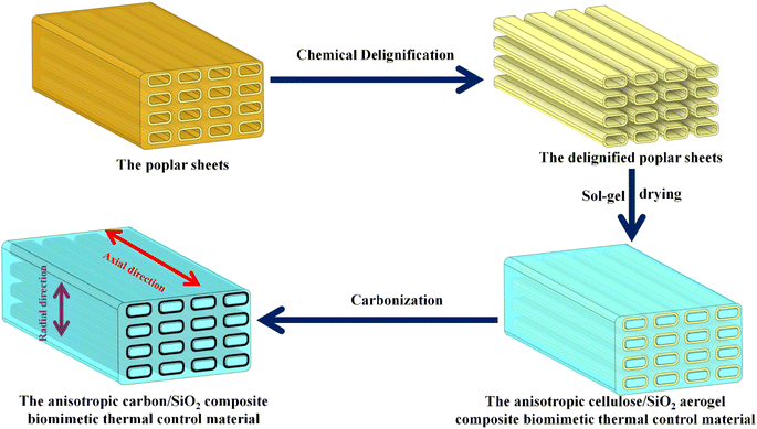 | ||
| Fig. 1 Illustration of fabrication process for the of the anisotropic carbon/SiO2 composite biomimetic thermal control material. | ||
2.3 Material characterization
The microstructure of the materials was observed by field emission scanning electron microscopy (SEM, JSM-6490LV, Japan). Information about the crystal structure of the material was characterized by X-ray diffractometer (D8 ADVANCE, Germany). The Raman spectrum of the material was collected on a Raman spectrometer (laser wavelength 532 nm, HORIBA Scientific LabRAM HR Evolution). X-ray photoelectron spectroscopy (XPS) of the material was acquired on an X-ray photoelectron spectrometer (monochrome Al Ka source, ESCALAB 250Xi, USA). The specific surface area and pore size distribution of the composite biomimetic thermal control material were calculated using the nitrogen absorption/desorption isotherm collected by the nitrogen absorption/desorption instrument (77 K, BELSORP-mini II Japan). The thermal degradation performance of composite biomimetic thermal control materials was evaluated using a thermogravimetric analyzer (TGA/DSC1 USA) (heating rate of 10 °C min−1 from room temperature to 800 °C in N2 atmosphere). The Fourier transform infrared (FT-IR) spectrum of the material was acquired on an infrared spectrometer (BRUKER TENSOR 27). The thermal conductivity of the composite biomimetic thermal control material at room temperature was measured on a multifunctional rapid thermal conductivity tester (DRE-III, transient plane heat source method).3 Results and discussion
Fig. 2a shows the micromorphology of the poplar sheets. The multiscale hierarchical porous anisotropic microstructure of thr poplar is covered by cellulose microfibers. The high-speed rotating saw blade can only make cellulose microfibers ductile fracture due to the good mechanical flexibility of cellulose microfibers in poplar sheets. Therefore, the CO2 laser was used to ablate the surface of the poplar sheet to remove the ductile fracture surface layer of the poplar sheet. Fig. 2b shows the surface morphology of the poplar sheets after CO2 laser ablation. After laser ablation, there were large conduits (about 80 μm) and abundant tracheids (about 10 μm) on the surface of the poplar sheets. Many microscope-scale pore structures are exposed on the surface of poplar wood sheets, which can promote the penetration of lignin removal solution to the interior of poplar wood sheets. This is conducive to the complete and efficient removal of lignin in the lignin removal process. Fig. 2c shows the surface microstructure of the delignified poplar sheets. The lignin removal solution can remove the lignin and some hemicellulose in the intercellular layer to form an intertubular cavity. The removal rate of lignin and hemicellulose from poplar sheets was about 42.1%. This indicates that lignin and hemicellulose in poplar sheets are almost completely removed. Therefore, the isolated tracheid structure is a microtubule structure composed of cellulose. The cellulose microtubules in the delignified poplar sheets still maintained an oriented aggregation microstructure. The abundant intertubular cavity structure, internal cavity structure and many pores in the wall of cellulose microtubule provide a broad operating space for controlling performance. The delignified poplar sheets have the same crystal structure as the poplar sheets (Fig. 2d). The characteristic diffraction peaks of (1![[1 with combining macron]](https://www.rsc.org/images/entities/char_0031_0304.gif) 0), (110), and (200) crystal faces belonging to the natural cellulose I crystal structure appear at 2θ of 15.8° and 22.3°, respectively.34 This indicates that the natural cellulose I crystalline structure of cellulose microtubules in delignified poplar sheets was not damaged by delignification. Therefore, the cellulose microtubules in the delignified poplar sheets are composed of cellulose microfibril with cellulose I crystalline structure, which are coiled at different angles. The delignified poplar sheets are easy to be moistened by SiO2 aerogel precursor solution. the SiO2 aerogel precursor solution was quickly and evenly filled into the multilevel cavity structure of the delignified poplar wood sheets from bottom to top along the axis of cellulose microtubules by capillary forces (Fig. S1a†). The concentration of SiO2 aerogel precursor solution has a certain regulation effect on the filling time (Fig. S1b†). The filling times of the CS-1.0, CS-2.5, CS-5.0 and CS-10.0 were 39.5 ± 7.5, 28.5 ± 3.5, 25.5 ± 5.5 and 16.3 ± 1.6 s, respectively. It can be seen that the filling time gradually decreases with the decrease of the concentration of SiO2 aerogel precursor solution.
0), (110), and (200) crystal faces belonging to the natural cellulose I crystal structure appear at 2θ of 15.8° and 22.3°, respectively.34 This indicates that the natural cellulose I crystalline structure of cellulose microtubules in delignified poplar sheets was not damaged by delignification. Therefore, the cellulose microtubules in the delignified poplar sheets are composed of cellulose microfibril with cellulose I crystalline structure, which are coiled at different angles. The delignified poplar sheets are easy to be moistened by SiO2 aerogel precursor solution. the SiO2 aerogel precursor solution was quickly and evenly filled into the multilevel cavity structure of the delignified poplar wood sheets from bottom to top along the axis of cellulose microtubules by capillary forces (Fig. S1a†). The concentration of SiO2 aerogel precursor solution has a certain regulation effect on the filling time (Fig. S1b†). The filling times of the CS-1.0, CS-2.5, CS-5.0 and CS-10.0 were 39.5 ± 7.5, 28.5 ± 3.5, 25.5 ± 5.5 and 16.3 ± 1.6 s, respectively. It can be seen that the filling time gradually decreases with the decrease of the concentration of SiO2 aerogel precursor solution.
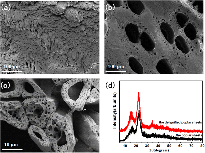 | ||
| Fig. 2 Surface microstructure of poplar (a), surface microstructure of laser treated poplar (b), microstructure of delignified poplar (c), XRD patterns of poplar and delignified poplar (d). | ||
Fig. 3 is the SEM image of anisotropic cellulose/SiO2 aerogel composite biomimetic thermal control material. The SiO2 aerogel precursor solutions with different concentrations between cellulose microtubules and within cellulose microtubules were converted into SiO2 aerogel. The cellulose/SiO2 aerogel composite biomimetic thermal control materials still exhibit an oriented and anisotropic aggregation microstructure. Obviously, there was obvious cracking between cellulose microtubules after drying with n-hexane at room temperature. The abundant axial microcracks in the cellulose/SiO2 aerogels composite biomimetic thermal control materials may help to increase the radial conduction thermal resistance of the composite biomimetic thermal control materials, and thus enhance the thermal anisotropy of the composite biomimetic thermal control material. The size of microcracks between composite microtubules increased with the decrease of the concentration of SiO2 aerogel precursor solution. The SiO2 aerogels filled between and inside cellulose microtubules show a typical microstructure of SiO2 aerogels prepared by TEOS sol–gel process, which is a 3D network structure randomly assembled by SiO2 nanoparticles. With the decrease of the concentration of SiO2 aerogel precursor solution, the size of SiO2 nanoparticles show a tendency to gradually increase, and the random stacking microstructure show a tendency to gradually loosen.
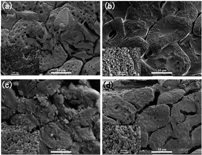 | ||
| Fig. 3 The SEM images of the anisotropic cellulose/SiO2 aerogel composite biomimetic thermal control material, (a) CS-1.0, (b) CS-2.5, (c) CS-5.0 and (d) CS-10.0. | ||
The interaction between SiO2 aerogels and cellulose microtubules in the cellulose/SiO2 aerogels composite biomimetic thermal control materials was characterized by infrared spectroscopy (Fig. 4a). The CS-X composite biomimetic thermal control material has an absorption peak attributed to Si–O–Si stretching vibration at about 795 cm−1, and an absorption peak attributed to Si–O–C stretching vibration appears at about 1059 cm−1 (the C–O stretching vibration absorption peak of cellulose also appears nearby, because the molar extinction coefficient of the C–O stretching vibration absorption peak of cellulose is 4–5 orders of magnitude lower than that of the Si–O stretching vibration absorption peak. Therefore, the absorption peak at about 1059 cm−1 is mainly from the Si–O–C stretching vibration in the cellulose/SiO2 aerogel composite biomimetic thermal control material).35 Si–O–C stretching vibration absorption peak indicates that SiO2 aerogel can form a strong and stable organic and inorganic interface structure with cellulose microtubules through chemical bond Si–O–C.
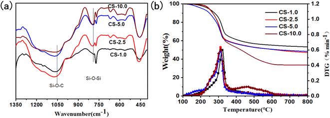 | ||
| Fig. 4 The FT-IR spectrums (a), and the TG curves (b) of the anisotropic cellulose/SiO2 composite biomimetic thermal control materials. | ||
The influence of the SiO2 aerogels on the thermal stability of the cellulose/SiO2 aerogel composite biomimetic thermal control materials was characterized by thermogravimetric analysis (Fig. 4b). The cellulose/SiO2 aerogel composite biomimetic thermal control material has the most obvious weight loss step in the temperature range of 100 to 800 °C. The weight loss step occurs in the temperature range of 229–356 °C, and the maximum weight loss rate occurs at 313 °C. The thermal loss can be attributed to the thermal degradation of the cellulose microtubules in a nitrogen atmosphere.36 The thermal degradation temperature of the cellulose/SiO2 aerogel composite biomimetic thermal control materials showed an increasing trend with the increase of the concentration of SiO2 aerogel precursor solution. At the carbonization temperature of 800 °C, the thermal degradation residual rate of the cellulose/SiO2 aerogel increased gradually from 33.6% of CS-10.0 to 53.4% of CS-1.0 composite biomimetic thermal control material.
Fig. 5 shows the microstructure of the carbon/SiO2 aerogel composite biomimetic thermal control materials at different solution concentrations of the SiO2 aerogel precursor solution. The anisotropic microstructure of the cellulose/SiO2 aerogel composite biomimetic thermal control materials is retained in carbon/SiO2 aerogel composite biomimetic thermal control materials. The reason is that the thermosetting cellulose natural polymer materials will not melt when thermal degradation occurs during the high temperature carbonization process. Therefore, cellulose composite microtubules are transformed into carbon composite microtubules after high temperature carbonization process. During the carbonization process, the volume shrinkage of the SiO2 aerogels filled between and inside cellulose microtubules does not match the volume shrinkage of the carbon microtubules carbonized from cellulose microtubules. This will result in separation between SiO2 aerogels and carbon composite microtubules. The contribution of the SiO2 aerogel filled between and inside cellulose microtubules to the radial heat insulation performance of the carbon/SiO2 aerogel composite biomimetic thermal control materials is significantly different. The main contributor to the excellent radial thermal insulation performance of the carbon/SiO2 aerogels is the SiO2 aerogels filled between the carbon composite microtubes. However, the SiO2 aerogels in carbon composite microtubules have little contribution to the radial thermal insulation performance of the carbon/SiO2 aerogels. The existence of the SiO2 aerogels in carbon composite microtubules is not conducive to the lightweight of the carbon/SiO2 aerogel composite biomimetic thermal control materials. With the decrease of the concentration of SiO2 aerogel precursor solution, the SiO2 aerogels filled in composite microtubules gradually decreases. The SiO2 aerogel even appeared only on the composite microtube wall of ACS-10.0 composite biomimetic thermal control material. In addition, the SiO2 aerogel filled between the composite microtubules also gradually decreases with the concentration of SiO2 aerogel precursor solution decreases (Fig. S2†). After carbonization at 800 °C, the SiO2 aerogels in the carbon/SiO2 aerogel composite biomimetic thermal control material still presents a 3D network structure formed by random assembly of SiO2 nanoparticles.
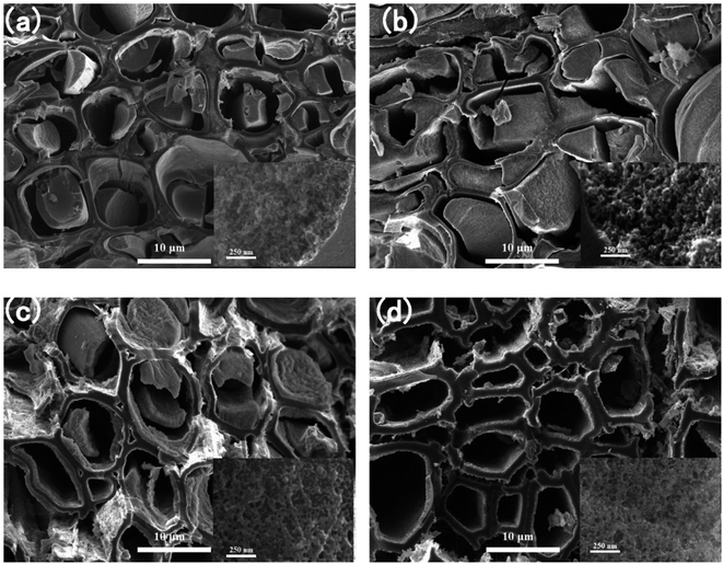 | ||
| Fig. 5 The SEM images of the anisotropic carbon/SiO2 aerogel composite biomimetic thermal control materials, (a) ACS-1.0, (b) ACS-2.5, (c) ACS-5.0 and (d) ACS-10.0. | ||
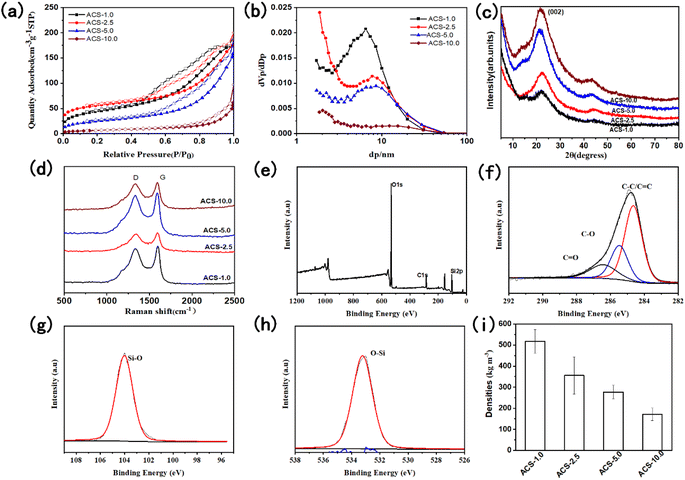
The pore structure and specific surface of the anisotropic carbon/SiO2 aerogel composite biomimetic thermal control materials were characterized by adsorption/desorption isotherm (Fig. 6a, b and Table S1†). According to IUPAC classification, the nitrogen adsorption/desorption isotherms of the anisotropic carbon/SiO2 aerogel composite biomimetic thermal control materials belong to type II adsorption/desorption isotherms with type H3 hysteresis loops. This indicates that the anisotropic carbon/SiO2 aerogel composite biomimetic thermal control material is a porous material with large pore structure. The H3 hysteresis loop shows that the pore structure of the anisotropic carbon/SiO2 aerogel composite biomimetic thermal control material is mainly a slit pore. The BET specific surface areas of the ACS-1.0, ACS-2.5, ACS-5.0 and ACS-10.0 composite biomimetic thermal control materials is 153, 183, 85 and 24 m2 g−1, respectively. The BET specific surface area of the anisotropic carbon/SiO2 aerogel composite biomimetic thermal control materials gradually decreases with the decrease of the concentration of the SiO2 aerogel precursor solution. The specific surface area of the composite biomimetic thermal control material is mainly derived from the manipulated filled SiO2 aerogels. The average pore size of the ACS-1.0, ACS-2.5, ACS-5.0 and ACS-10.0 composite biomimetic thermal control materials is 5.8, 7.3, 8.8 and 11.5 nm, respectively. The average pore diameter of the anisotropic carbon/SiO2 aerogel composite biomimetic thermal control materials gradually increases with the decrease of the concentration of SiO2 aerogel precursor solution. The pore size distribution peak of the ACS-10.0 composite biomimetic thermal control material appears at 2.0 nm. However, the pore size distribution peak of Other composite biomimetic thermal control materials appears at about 6.5 nm. The total pore volume of the ACS-1.0, ACS-2.5, ACS-5.0 and ACS-10.0 composite biomimetic thermal control materials is 0.2788, 0.2498, 0.2450 and 0.0930 cm3 g−1, respectively. The total pore volume of the composite biomimetic thermal control material decreases gradually with the decrease of the concentration of SiO2 aerogel precursor solution.
Fig. 6c shows the XRD pattern of the anisotropic carbon/SiO2 aerogel composite biomimetic thermal control material. The diffraction peak at 21.6° is attributed to the characteristic diffraction peak of the amorphous carbon (002) crystal face. This indicates that cellulose microtubules are transformed into amorphous carbon microtubules after high temperature carbonization. The axial thermal conductivity of the ACS-X composite biomimetic thermal control material is mainly determined by the thermal conductivity of the amorphous carbon in composite carbon microtubules. In addition, there is no characteristic diffraction peak of the SiO2 aerogels in the XRD pattern of the ACS-X composite biomimetic thermal control material. Therefore, the SiO2 aerogel in ACS-X composite biomimetic thermal control material is an amorphous crystal structure, which will help to improve the thermal insulation performance in the radial direction of the ACS-X composite biomimetic thermal control material.
In order to further evaluate the carbon structure of the ACS-X composite biomimetic thermal control material, the composite biomimetic thermal control materials were tested by Raman spectroscopy (Fig. 6d). The characteristic peaks at 1329 cm−1 and 1590 cm−1 in the Raman spectra of the ACS-X composite biomimetic thermal control material are attributed to the D-band characteristic peak of the disordered carbon and the G-band characteristic peak of the graphitized carbon, respectively. The carbon material in the ACS-X composite biomimetic thermal control material has the crystal structure of amorphous carbon. The ID/IG ratio of the ACS-1.0, ACS-2.5, ACS-5.0 and ACS-10.0 composite biomimetic thermal control materials is 0.94, 0.96, 0.96 and 0.96, respectively. The ID/IG ratio of the ACS-X composite biomimetic thermal control material is almost unchanged with the increase of the concentration of SiO2 aerogel precursor solution. The controlled filled SiO2 aerogel has little effect on the crystal structure of the carbon material in the ACS-X composite biomimetic thermal control material.
The X-ray photoelectron spectroscopy was used to analyse the chemical elements and chemical environment on the surface of the anisotropic ACS-2.5 composite biomimetic thermal control material (Fig. 6e–h). ACS-2.5 composite biomimetic thermal control material is mainly composed of C, O and Si element with atomic proportion of 17.01%, 55.66% and 27.33%, respectively. The XPS spectrum of the high resolution C 1s can be deconvolved into three peaks, which are attributed to C–C/C![[double bond, length as m-dash]](https://www.rsc.org/images/entities/char_e001.gif) C (284.8 eV), C–O (285.5 eV) and C
C (284.8 eV), C–O (285.5 eV) and C![[double bond, length as m-dash]](https://www.rsc.org/images/entities/char_e001.gif) O (286.4 eV). The C element on the surface of the ACS-2.5 composite biomimetic thermal control material is mainly derived from amorphous carbon formed by high temperature degradation of cellulose. The high-resolution O 1s XPS spectrum can deconvolve a peak attributed to O–Si (533.2 eV), indicating that the oxygen element on the surface of ACS-2.5 composite biomimetic thermal control material comes from SiO2 aerogel. The XPS spectrum of the high-resolution Si 2p can deconvolve a symmetric unimodal ascribed to Si–O (104.0 eV), indicating that the Si element in the ACS-2.5 composite biomimetic thermal control material has only one Si4+ oxidation state chemical structure.
O (286.4 eV). The C element on the surface of the ACS-2.5 composite biomimetic thermal control material is mainly derived from amorphous carbon formed by high temperature degradation of cellulose. The high-resolution O 1s XPS spectrum can deconvolve a peak attributed to O–Si (533.2 eV), indicating that the oxygen element on the surface of ACS-2.5 composite biomimetic thermal control material comes from SiO2 aerogel. The XPS spectrum of the high-resolution Si 2p can deconvolve a symmetric unimodal ascribed to Si–O (104.0 eV), indicating that the Si element in the ACS-2.5 composite biomimetic thermal control material has only one Si4+ oxidation state chemical structure.
The density of the ACS-1.0, ACS-2.5, ACS-5.0 and ACS-10.0 composite biomimetic thermal control materials is 517.8 ± 55.9, 355.7 ± 87.9, 276.8 ± 31.6 and 171.4 ± 29.6 kg m−3, respectively (Fig. 6i). Obviously, the density of the composite biomimetic thermal control materials shows a gradually increasing trend with the gradual increase of the concentration of SiO2 aerogel precursor solution. The density of the ACS-1.0 composite biomimetic thermal control material is more than 3 times that of the ACS-10.0 composite biomimetic thermal control material.
Fig. 7a shows the axial and radial thermal conductivity of the carbon/SiO2 aerogel composite biomimetic thermal control material prepared by carbonization at 800 °C in an inert atmosphere. The axial thermal conductivity of the ACS-1.0, ACS-2.5, ACS-5.0 and ACS-10.0 composite biomimetic thermal control materials is 0.32 ± 0.02, 0.36 ± 0.03, 0.51 ± 0.01 and 0.73 ± 0.07 W m−1 k−1, respectively. The axial thermal conductivity of the carbon/SiO2 aerogel composite biomimetic thermal control material gradually increases with the gradual decrease of the concentration of the SiO2 aerogel precursor solution. The axial thermal conductivity of the carbon/SiO2 aerogel composite biomimetic thermal control material is mainly determined by the thermal conductivity of the carbon composite microtubule structure. The radial thermal conductivity of the ACS-1.0, ACS-2.5, ACS-5.0 and ACS-10.0 composite biomimetic thermal control materials is 0.22 ± 0.004, 0.11 ± 0.003, 0.15 ± 0.004 and 0.28 ± 0.01 W m−1 k−1, respectively. The radial thermal conductivity of the carbon/SiO2 aerogel composite biomimetic thermal control material first decreases and then increases with the gradual decrease of the concentration of SiO2 aerogel precursor solution. The radial thermal conductivity of the ACS-10.0 composite biomimetic thermal control materials is mainly determined by the SiO2 aerogel. Therefore, the microstructure and distribution of the SiO2 aerogel significantly affect the thermal conductivity of the ACS-10.0 composite biomimetic thermal control materials. The dense microstructure of the SiO2 aerogels with high concentration of the SiO2 aerogel precursors is not conducive to improving the thermal insulation performance. As the concentration of the SiO2 aerogel precursor solution decreases gradually, the microstructure of the SiO2 aerogel becomes loose gradually. The loose microstructure of the SiO2 aerogel is conducive to further improving the thermal insulation performance. However, when the concentration of the SiO2 aerogel precursors gradually decreases, the SiO2 aerogel layer covering the outer wall of the composite microtubules gradually becomes thinner. The composite microtubules covered with a thin SiO2 aerogel layer increase the thermal conductivity. The ratio of the axial thermal conductivity to radial thermal conductivity of the ACS-1.0, ACS-2.5, ACS-5.0 and ACS-10.0 composite biomimetic thermal control materials is 1.4, 3.2, 3.3 and 2.5, respectively.
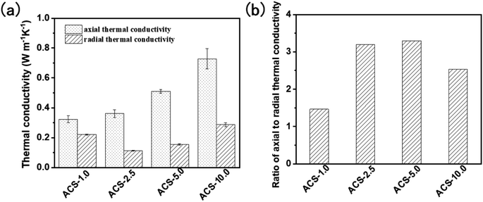 | ||
| Fig. 7 Thermal conductivity (a) and the ratio of the axial thermal conductivity to radial thermal conductivity (b) of the anisotropic carbon/SiO2 composite biomimetic thermal control materials. | ||
4 Conclusions
In this paper, the filling of the SiO2 aerogel into the multi-layer pore structure and microtubule structure originally occupied by lignin was controlled by the process of the axial self-adsorption, limited sol–gel and natural drying. Then the anisotropic composite biomimetic thermal control materials were prepared by high temperature carbonization and their properties were evaluated. The SiO2 aerogel precursor solution was quickly and evenly filled into the multilevel cavity structure of the delignified poplar wood sheets from bottom to top along the axis of the cellulose microtubules by capillary forces. The minimum filling time of 35 mm axial distance is only 16.3 ± 1.6 s. The SiO2 aerogel can form a strong and stable organic–inorganic interface structure with cellulose microtubules through Si–O–C chemical bond. The ACS-X composite biomimetic thermal control material obtained after carbonization inherits the anisotropic oriented microstructure. The axial thermal conductivity of the CS-X composite biomimetic thermal control material is mainly determined by the thermal conductivity of the carbon composite microtubule structure. The SiO2 aerogel filled between carbon composite microtubules and abundant axial microcracks endow the ACS-X composite biomimetic thermal control material good radial heat insulation performance. The maximum specific surface area of the ACS-X composite biomimetic thermal control material is 183 m2 g−1, and the maximum density is 517.8 ± 55.9 kg m−3. The maximum axial thermal conductivity of the ACS-X composite biomimetic thermal control material is 0.73 ± 0.07 W m−1 k−1, and the radial thermal conductivity is 0.28 ± 0.01 W m−1 k−1. The maximum ratio of axial thermal conductivity to radial thermal conductivity of the ACS-X composite biomimetic thermal control material is 3.3.Data availability
The authors declare that the data and materials were available.Author contributions
SZ and XS: idea for the article, literature search and analysis, experiment, writing and revision of the manuscript. LW: idea for the article, analysis, revision of the manuscript. BA: analysis, revision of the manuscript. HS: experimental protocol design. YC: revision of the manuscript.Conflicts of interest
The authors declare no competing interests.References
- X.-J. Zhu and F. Li, Int. J. Mod. Phys. B, 2020, 34, 2040105 CrossRef.
- J. Sun and Q. Zhu, AIP Adv., 2019, 9, 025203 CrossRef.
- Z. Xiaojun, L. Feng, O. Dongbin, C. Lianzhong and Z. Kai, Mechanics in Engineering, 2019, 41, 388–392 Search PubMed.
- A. B. Peters, D. Zhang, S. Chen, C. Ott, C. Oses, S. Curtarolo, I. McCue, T. M. Pollock and S. Eswarappa Prameela, Nat. Commun., 2024, 15, 3328 CrossRef CAS.
- S. Zhang, X. Li, J. Zuo, J. Qin, K. Cheng, Y. Feng and W. Bao, Prog. Aeronaut. Sci., 2020, 119, 100646 CrossRef.
- O. Uyanna and H. Najafi, Acta Astronaut., 2020, 176, 341–356 CrossRef.
- R. Wang, Z. Wang, H. Zheng and H. Song, International Journal of Aeronautical and Space Sciences, 2020, 21, 347–362 CrossRef.
- K. Xiong, Z.-p. Sun, J.-c. Hu, C. Ma, J.-t. Wang, X. Ge, W.-m. Qiao and L.-c. Ling, New Carbon Mater., 2024, 39, 271–282 CrossRef CAS.
- H.-D. Guan, X.-B. He, Z.-J. Zhang, T. Zhang and X.-H. Qu, New Carbon Mater., 2023, 38, 804–824 CrossRef CAS.
- G.-m. Ye, K. Shi, H. Wu, D. Huang, C. Ye, T. OUYang, S.-p. Zhu, Z. Fan, H.-b. Liu and J.-s. Liu, New Carbon Mater., 2024, 39, 334–344 CrossRef CAS.
- M. P. Ansell, in Wood Composites, Elsevier, 2015, pp. 3–26 Search PubMed.
- P. Trtik, J. Dual, D. Keunecke, D. Mannes, P. Niemz, P. Stähli, A. Kaestner, A. Groso and M. Stampanoni, J. Struct. Biol., 2007, 159, 46–55 CrossRef CAS.
- R. Astley, J. Harrington and K. Stol, Trans. N. Z. Inst. Eng., Electr./Mech./Chem. Eng. Sect., 1997, 24, 21–29 Search PubMed.
- S. E. Stanzl-Tschegg, Int. J. Fract., 2006, 139, 495–508 CrossRef CAS.
- K. Schulgasser and A. Witztum, Wood Sci. Technol., 2015, 49, 389–401 CrossRef CAS.
- D. Goring, S. Saka and T. Higuchi, Biosynthesis and Biodegradation of Wood Components, 1988, pp. 51–62 Search PubMed.
- M. Fujita and H. Harada, Wood Cellul. Chem., 2000, 2, 1–49 Search PubMed.
- J. Zhao, S. Feng, Z. Kou, F. Meissner, U. Ruisinger and J. Grunewald, Constr. Build. Mater., 2023, 398, 132375 CrossRef.
- Y. I. Golovin, A. I. Tyurin, D. Y. Golovin, A. A. Samodurov and I. A. e. Vasyukova, Tech. Phys. Lett., 2021, 47, 92–95 CrossRef CAS.
- Y.-P. Hu, W.-B. Li, S. Wu, Y.-J. Wang, W.-Z. Zhong and H. Zhang, Int. J. Thermophys., 2023, 44, 131 CrossRef CAS.
- Y. Meng, J. Majoinen, B. Zhao and O. J. Rojas, Composites, Part B, 2020, 199, 108296 CrossRef CAS.
- J. Li, C. Chen, J. Y. Zhu, A. J. Ragauskas and L. Hu, Acc. Mater. Res., 2021, 2, 606–620 CrossRef CAS.
- Y. Wu, J. Zhou, Q. Huang, F. Yang, Y. Wang and J. Wang, Polymers, 2020, 12, 661 CrossRef CAS.
- K. Gao, J. Song, Q. Niu, Q. Tang, X. Sun and L. Wang, J. Mater. Sci., 2023, 58, 13009–13018 CrossRef CAS.
- J. R. Barnett and V. A. Bonham, Biol. Rev., 2004, 79, 461–472 CrossRef CAS.
- H. Lichtenegger, M. Müller, O. Paris, C. Riekel and P. Fratzl, J. Appl. Crystallogr., 1999, 32, 1127–1133 CrossRef CAS.
- M. Antlauf, N. Boulanger, L. Berglund, K. Oksman and O. Andersson, Biomacromolecules, 2021, 22, 3800–3809 CrossRef CAS PubMed.
- A.-G. Niculescu, D.-I. Tudorache, M. Bocioagă, D. E. Mihaiescu, T. Hadibarata and A. M. Grumezescu, Nanomaterials, 2024, 14, 469 CrossRef CAS.
- S. C. Zhang, Y. F. Chen, W. Wu, H. R. Sun, G. H. Wang, X. K. Sun, K. Fang and F. Zhang, Key Eng. Mater., 2016, 697, 433–436 Search PubMed.
- Z.-h. Liu, Y.-d. Ding, F. Wang and Z.-p. Deng, Constr. Build. Mater., 2016, 122, 548–555 CrossRef CAS.
- A. Katti, N. Shimpi, S. Roy, H. Lu, E. F. Fabrizio, A. Dass, L. A. Capadona and N. Leventis, Chem. Mater., 2006, 18, 285–296 CrossRef CAS.
- Q. Xian-Lang, Y. Min, L. Hong, X. Jia-Wen, R. Mu-Su and S. Jin-Liang, J. Porous Mater., 2022, 29, 1027–1037 CrossRef.
- B. Shi, L. Xie, B. Ma, Z. Zhou, B. Xu and L. Qu, Gels, 2022, 8, 744 CrossRef CAS.
- A. Babaei-Ghazvini, B. Vafakish, R. Patel, K. J. Falua, M. J. Dunlop and B. Acharya, Int. J. Biol. Macromol., 2023, 128834 Search PubMed.
- D. Han, X. Sun, S. Zhang, L. Wu, B. Ai, H. Sun and Y. Chen, RSC Adv., 2024, 14, 12911–12922 RSC.
- H. L. Ornaghi, F. G. Ornaghi, R. M. Neves, F. Monticeli and O. Bianchi, Cellulose, 2020, 27, 4949–4961 CrossRef CAS.
Footnote |
| † Electronic supplementary information (ESI) available: Data associated with this article can be found in ESI. See DOI: https://doi.org/10.1039/d4ra04833d |
| This journal is © The Royal Society of Chemistry 2024 |

