
 Open Access Article
 This Open Access Article is licensed under a Creative Commons Attribution-Non Commercial 3.0 Unported Licence
Unveiling the reactor effect: a comprehensive characterization of biochar derived from rubber seed shell via pyrolysis and in-house reactor
Mashrafi Bin Mobarak a,
Nigar Sultana Pinky*a,
Sonjida Mustafia,
Fariha Chowdhuryb,
Aynun Naharc,
Umme Sarmeen Akhtara,
Md. Saiful Quddusa,
Sabina Yasminc and
Md. Ashraful Alama
a,
Nigar Sultana Pinky*a,
Sonjida Mustafia,
Fariha Chowdhuryb,
Aynun Naharc,
Umme Sarmeen Akhtara,
Md. Saiful Quddusa,
Sabina Yasminc and
Md. Ashraful Alama
aInstitute of Glass and Ceramic Research and Testing (IGCRT), Bangladesh Council of Scientific and Industrial Research (BCSIR), Dhaka-1205, Bangladesh. E-mail: nigar.pinkyacce@gmail.com
bBiomedical and Toxicological Research Institute (BTRI), Bangladesh Council of Scientific and Industrial Research (BCSIR), Dhaka-1205, Bangladesh
cInstitute of National Analytical Research and Service (INARS), Bangladesh Council of Scientific and Industrial Research (BCSIR), Dhaka-1205, Bangladesh
First published on 19th September 2024
Abstract
Utilization of agricultural waste to produce biochar has already proven to be an efficient method for transforming waste into valuable resources. In this study, rubber seed shell (RSS) was utilized to prepare two biochar samples via an in-house built reactor (RSSBC-1) and a pyrolysis reactor (RSSBC-2) under identical conditions (600 °C for 3 h at a heating rate of 10 °C per min). A comprehensive characterization of the prepared biochar samples was carried out to reveal the reactor effect on the biochar properties. For this, proximate and ultimate analyses were carried out which estimated the carbon stability, polarity, and aromaticity of the biochar samples. For RSSBC-1, C and N content were higher, whereas H and O content were higher for RSSBC-2, as found from elemental, EDX, and XPS analyses. Point of zero charge (PZC) values of 7.65 and 6.14 for RSSBC-1 and RSSBC-2, respectively, emphasized the importance of pH in the removal of ionic contaminants. Furthermore, the superiority of RSSBC-1 in terms of specific surface area of 336.02 m2 g−1 compared to 299.09 m2 g−1 of RSSBC-2 was articulated by BET analysis. XPS and FESEM analyses revealed the chemical state of surface elements and surface morphology, respectively of the biochar samples. XRD patterns assured the amorphous nature of biochar samples, and functional groups were well depicted by FTIR analysis. DLS showed a larger average hydrodynamic diameter for RSSBC-2 (248.68 nm) with a zeta potential of −14.91 mV compared to RSSBC-1 (115.23 nm) with a heterogeneous charge distribution (−16.72 mV and +37.61 mV). TGA analysis revealed the thermal stability of both biochar samples. Overall, the results explicitly depict a distinction in the properties of biochar samples prepared in two different reactors, where RSSBC-1, with its superior properties suggests the in-house built reactor as a promising alternative to expensive pyrolytic reactors for waste valorization.
1. Introduction
The thermal breakdown of plant-derived biomass in the total or partial absence of oxygen, known as pyrolysis, can be harnessed to produce a range of valuable byproducts. These include combustible gases like hydrogen (H2), carbon monoxide (CO), and methane (CH4), along with volatile oils, tarry vapors, and a solid residue rich in carbon known as char.1 Biochar, a specific type of char, is a term that lacks a precise definition but is generally understood as char derived from biomass intended for soil application. The International Biochar Initiative (IBI) defines biochar as “a solid material obtained from the carbonization and thermochemical conversion of biomass in an oxygen-limited environment”.2 The term “biochar” was coined to differentiate activated carbon produced from biomass from that made from fossil fuels.3 Biochar encompasses a variety of materials produced under different levels of control, with or without complete exclusion of oxygen, including traditional charcoal.4 Biochar, like char in general, is primarily composed of stable aromatic forms of organic carbon. This composition sets it apart from the carbon found in the original biomass feedstock, making it resistant to rapid decomposition and release as carbon dioxide (CO2) back into the atmosphere. Even under favorable environmental and biological conditions, such as those found in soil ecosystems, biochar remains relatively stable and contributes to long-term carbon sequestration.1,4The type of feedstock used in biochar production significantly influences its properties. Different feedstocks have varying compositions that impact characteristics such as adsorption capacity, nutrient retention, total organic carbon, mineral elements, surface area, and pH of biochar.5,6 The feedstock properties, both physical and chemical, play a crucial role in determining biochar parameters like total organic carbon, fixed carbon, mineral elements, surface area, and pH.7,8 The content of labile carbon fractions in biochar, such as water-soluble carbohydrates (WSC) and dissolved organic carbons (DOCs), is notably affected by the type of feedstock used.5 Biochars derived from food waste tend to have a less aromatic structure and higher contents of labile carbon fractions, which can reduce biochar stability compared to biochars from lignocellulosic feedstocks.9,10 Therefore, selecting the appropriate feedstock is crucial for tailoring biochar properties for specific applications in soil improvement, carbon sequestration, and environmental remediation.
Different methods of biochar preparation, including pyrolysis,11 gasification,12 torrefaction,13 and flash carbonization,14 significantly influence the physical and chemical properties of biochar. Pyrolysis, the most common method, can be slow or fast, with temperature playing a crucial role in biochar characteristics. Gasification produces biochar along with syngas, while torrefaction and flash carbonization offer alternative approaches.8 The choice of preparation method impacts biochar surface area, aromaticity, recalcitrance, and labile carbon fractions, affecting its suitability for various applications like soil improvement and carbon sequestration.9 Pyrolysis is a favored method for biochar production due to its versatility in utilizing various biomass feedstocks, high biochar yield potential, and the generation of valuable co-products like bio-oil and syngas.15 The environmental benefits of biochar, such as carbon sequestration and soil improvement, further contribute to its popularity.16 Pyrolysis is scalable to industrial levels, and ongoing technological advancements continue to enhance its efficiency and applicability. These factors established pyrolysis as a widely accepted and promising method for biochar production.4
Although pyrolysis has become the most commonly followed method for biochar preparation, procurement of pyrolytic reactors has become a tough task due to high initial investment. As an alternative, an in-house built reactor for biochar preparation was reported in our previous study where biochar was prepared from corncob biomass and successfully implemented for wastewater treatment.17 Similar arrangement was also reported in the work of Suwunwong et al.18 With such an arrangement, facile synthesis of biochar is possible, considering the lower cost associated with the procurement of a laboratory-scale muffle furnaces. To address how this in-house built reactor affect the biochar properties, herein, we prepared two biochar samples using a commercial pyrolytic reactor and our in-house built reactor. Rubber seed shells (RSS), a feedstock biomass with 30–50% carbon content, were chosen as the precursor. They are collected from the rubber tree known as Hevea brasiliensis. Studies have demonstrated that, biochar produced from RSS exhibits characteristics such as a higher calorific value, higher fixed carbon content, lower ash content, and lower moisture content, making it a promising solid fuel option.19,20
While numerous studies have explored effects of different factors such as pyrolysis temperature, feedstock type, and residence time, few have directly compared the impact of different reactor designs on biochar properties. For instance, Del Pozo et al. reported the effect of reactor scale on biochar properties in terms of TGA, pH, density, proximate and ultimate analyses, HHV, FTIR, and GCMS.21 In another study, Das et al. reported the effect of different pyrolysis reactors (hydrothermal, vertical and horizontal tube reactor) on the flammability and mechanical properties.22 To address this research gap, a comprehensive characteristics analysis of biochars prepared by a pyrolytic reactor and an in-house built reactor was carried out. To the best of our knowledge, no such comparison was carried out in order to find whether the in-house system produces biochar with similar or superior properties to the pyrolytic reactor.
2. Materials and methods
2.1. Materials
The rubber seed shell (RSS) raw material utilized in this study was sourced from the Fatikchhari rubber garden in Chattogram, Bangladesh (22.6840°N91.7893°E). Sodium hydroxide (NaOH), hydrochloric acid (HCl), and ethanol (C2H5OH) were procured from Sigma-Aldrich, UK, through a local supplier. Deionized (DI) water was employed in preparing solutions for all experiments.2.2. Methods
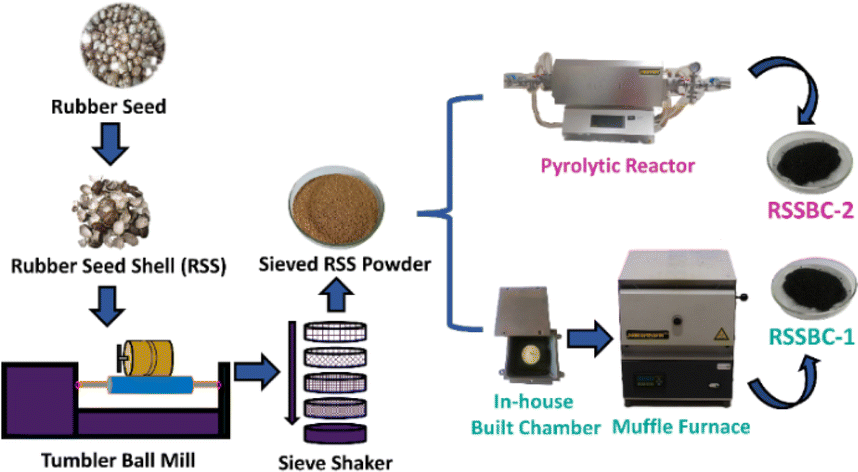 | ||
| Fig. 1 Schematic representation of the preparation procedure of biochar from rubber seed shell using in-house built reactor and pyrolytic reactor. | ||
 | (1) |
The moisture-free sample (in a dried crucible) was placed in a muffle furnace at 575 ± 25 °C for 180 min to estimate the ash content (ASTM E1755-01) and volatile matter (at 950 ± 25 °C for 7 min) on dry basis (ASTM D3175-11). The equations below aided in calculating the ash content and volatile matter.
 | (2) |
 | (3) |
 | (4) |
The following equation was used to calculate the biochar yield, which was defined as the mass of the biochar product divided by the mass of biomass.25
 | (5) |
The pH of RSSBC samples was measured by mixing the sample with deionized water, maintaining a ratio of 1![[thin space (1/6-em)]](https://www.rsc.org/images/entities/char_2009.gif) :10 (w/v), and then shaking in an orbital shaker at 150 rpm for 2 hours. The pH of the mixture was then measured with a pH meter (sensION + pH31) at room temperature.26
:10 (w/v), and then shaking in an orbital shaker at 150 rpm for 2 hours. The pH of the mixture was then measured with a pH meter (sensION + pH31) at room temperature.26
The point of zero charge (PZC), also known as the isoelectric point, of RSSBC was determined using a modified version of the pH drift method, as described in existing literature.27,28 0.02 g of RSSBC was weighed, and 50 ml of a 0.1 M NaCl solution was added. The pH of this solution was set at 3, 4, 5, 6, 7, 8, 9, 10, 11, and 12 using NaOH and HCl solutions. This mixture was then subjected to orbital shaking at 150 rpm for 12 hours at RT. After shaking, the pH of the solutions was recorded. The plot of the change in pH with respect to the initial pH of the sample produces a point of intersection on the x-axis which is referred to as the PZC of the RSSBC samples.29
The elements of RSSBC, more specifically C, H, N, S, and O, were quantified by an elemental analyzer (Vario EL Cube, Elementar, Germany). The presence of functional groups in RSSBC was identified with FTIR (IR Prestige-21, Shimadzu Corp. MIRacle-10 ATR accessory) and Raman (HORIBA Macro-RAM with laser wavelength of 785 nm) analysis. The hydrodynamic diameter as well as the zeta potential of the biochar samples were determined by a DLS instrument (Malvern Panalytical Zetasizer Ultra). The samples were finely dispersed in DI water and sonicated for 30 min before DLS analysis. The specific surface area of the prepared biochar was determined with the aid of a BET (Brunauer–Emmett–Teller) sorptometer (BET-201-A, PMI, Tampa, FL, USA). Pore size distribution was estimated using the Barrett–Joyner–Halenda (BJH) method. The micropore surface area values were estimated using the t-plot method. Phase analysis was carried out by an X-ray powder diffractometer (XRD) (Rigaku Smart Lab) under the following operating conditions: 2θ range = 10° to 80°; scan rate = 30° min−1; voltage and current = 40 kV and 50 mA; λ of Cu Kα radiation = 1.54060 Å. X-ray photoelectron spectroscopy (XPS) was employed (K-Alpha, Thermo Scientific) for the elemental confirmation and oxidation state of the elements present in the prepared biochar. FESEM (JEOL JSM-7610F) images were captured for the morphological study of the prepared biochar and the integrated EDX machine helped us out with the elemental analysis. Thermal analysis in terms of TGA (thermogravimetric analysis) and DTG (derivative thermogravimetry) was carried out using a simultaneous thermal analyzer (STA) (NETZSCH STA 449F5).
3. Results and discussion
3.1. Proximate and physical property analysis
The results of proximate analysis and physical property evaluation (pH, thermostable fraction, and biochar yield) of the RSS biomass and the RSSBC samples are compiled in Table 1.| Sl. No. | Parameters | RSS biomass | RSSBC-1 | RSSBC-2 |
|---|---|---|---|---|
| 1 | Moisture content | 9.58 | 2.4 | 2.2 |
| 2 | Volatile matter | 68.53 | 15.78 | 15.21 |
| 3 | Ash content | 1.53 | 13.78 | 16.06 |
| 4 | Fixed carbon | 20.36 | 68.04 | 66.53 |
| 5 | Yield | — | 25.1 | 25.6 |
| 6 | pH | — | 4.73 | 4.32 |
| 7 | Thermostable fraction | — | 230.1 | 212.7 |
According to the data presented in Table 1, the moisture content and volatile matter were higher for the RSS biomass, followed by the RSSBC-1 and RSSBC-2 samples. On the contrary, ash content was higher for the RSSBC-2 sample, followed by the RSSBC-1 and RSS biomass samples. Volatile matter and ash content are largely influenced by the production process and type of feedstock. Both the prepared biochar samples possess high carbon sequestration potential since a volatile matter content lower than 80% typically indicates such.30 The RSSBC-1, in comparison, has higher carbon sequestration potential. The pH of the biochar samples is found to be acidic in nature since biochar prepared from wood feedstocks, biosolids, and herbaceous feedstocks demonstrated a neutral to acidic pH.31 Biochar yield was almost the same, with the RSSBC-2 sample having a marginally higher yield.
3.2. Elemental analysis
The major elements present in the raw material (RSS biomass) as well as in the prepared biochar (RSSBC-1 and RSSBC-2), along with their composition, are presented in Table 2. Apart from elemental composition, various other molar ratios, such as H/C, O/C and (O + N)/C are also calculated and tabulated in Table 2.Analyzing the composition of RSS biomass provides valuable information on characteristics like polarity index, hydrophilicity, and aromaticity. This analysis aids in evaluating the suitability of biochar for its intended use.17 According to the results obtained, the prepared biochars have a higher C content than the RSS biomass, albeit the O and H contents are higher in the biomass. The increase in the C content of the biochar is possibly due to the removal of hydroxyl (–OH) groups during dehydration.33 Keeping this in mind, the removal of –OH groups was higher for RSSBC-1 as it has a higher C content than the RSSBC-2. The content of O and H declines within the biochar, compared to the RSS biomass, as the pyrolysis temperature is applied. This reduction in O content occurs as a result of dehydration, decarbonylation, and decarboxylation reactions. On the other hand, the reduction of H content is likely a result of the biochar undergoing aromatization and the subsequent release of hydrogen gas, as light molecular hydrocarbons are formed during the pyrolysis process.34 The RSS utilized in the study has a low N and zero S content, indicating environmentally friendly raw materials with minimal nitrogen oxide and zero sulfur oxide emissions during pyrolysis.35 The aromaticity index of biochar is determined by its H/C ratio, which exhibited a decline in both biochars at equal magnitude. As the pyrolysis temperature was imposed, the H/C ratio decreased, signaling a shift towards greater aromaticity and carbon content in the produced biochar, accompanied by the development of a graphite-like structure.36
The molar ratio of O/C serves as an indicator of biochar polarity. The findings demonstrate a decline in the O/C ratio for both biochars. Lower O/C values observed in biochar suggest a reduction in polar functional groups on its surface. Reduced ratios of hydrogen to carbon (H/C) and oxygen to carbon (O/C) result in decreased emissions of CO2, smoke, and water vapor during combustion, thereby enhancing combustion efficiency. This makes biochar suitable for use as solid fuel.37 The longevity of biochar is a critical factor to estimate, determined by its O/C ratio. When the O/C ratio falls below 0.2, the half-life of biochar is expected to endure for over 1000 years.36 Based on this observation, both RSSBC-1 and RSSBC-2 are predicted to have a half-life exceeding 1000 years.38 The (O + N)/C ratio is a useful metric for characterizing the chemical properties and potential applications of biochars. It provides insights into the polarity, hydrophilicity, and water-holding capacity of the biochar, which are important considerations in areas like soil amendment, water treatment, and carbon sequestration.39 The RSSBC-2 sample has a higher (O + N)/C ratio (0.15%) than the RSSBC-2 sample (0.09%). A higher (O + N)/C ratio indicates that there might be more polar functional groups such as hydroxyl (–OH), carboxyl (–COOH), and nitrogen-containing groups. These polar groups can increase the hydrophilicity and reactivity of the biochar. In contrast, a lower (O + N)/C ratio suggests the presence of fewer polar functional groups and a more aromatic, hydrophobic structure. Such biochars may be better suited for applications like carbon sequestration where high aromaticity is desirable.40
3.3. Elemental analysis by EDX
Elemental analysis of the prepared biochar samples was also carried out with the aid of EDX. Qualification and quantification of the major elements (C, N, O, and S) along with the molar ratio based on mass% were done for both the RSSBC-1 and RSSBC-2 samples. EDX spectra and the respective composition of elements are presented in Fig. 2.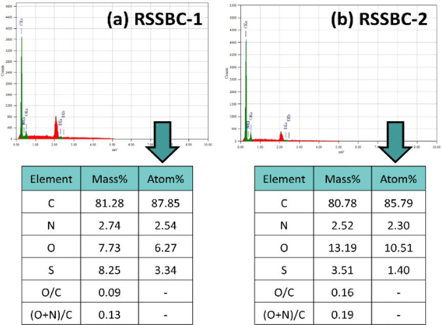 | ||
| Fig. 2 EDX analysis of the prepared biochar samples: (a) RSSBC-1 and (b) RSSBC-2. | ||
The C and N content of RSSBC-1 was slightly higher (0.50 mass% and 0.22 mass% higher, respectively) than the RSSBC-2 sample. Conversely, the O content was higher for the RSSBC-2 sample (5.46 mass% higher). A similar trend was also found in the elemental analysis, as described in the elemental analysis section. Interestingly, the EDX technique detected the presence of S content, which wasn't found in the elemental analysis. The S content was higher in the RSSBC-1 sample (4.74 mass% higher). In terms of molar ratios, the O/C and (O + N)/C contents were higher for the RSSBC-2 sample. The O/C and (O + N)/C contents of the RSSBC-2 sample were 0.16 mass% and 0.19 mass%, respectively, whereas the RSSBC-1 sample had 0.09 mass% and 0.13 mass%, respectively.
3.4. XPS study
XPS analysis of the prepared RSSBC-1 and RSSBC-2 biochar samples was carried out to investigate the surface elemental composition, chemical state, and type of bonding present. Fig. 3 represents the XPS spectrum, which includes survey as well as narrow scan plots. The survey scan of the prepared biochar detected the presence of C, N, O, Na, and Mg on both surfaces of the biochar. Table 3 lists the peak positions, atomic%, area, and corrected area based on the sensitivity factor of the detected elements. The % of C content found through this XPS survey analysis was 82.58 atom% and 77.12 atom% for RSSBC-1 and RSSBC-2, respectively. On the contrary, the O content was higher for the RSSBC-2 sample. This finding is well aligned with the results obtained through elemental and EDX analyses. The N content was higher for RSSBC-2 (1.49 atom%) than the RSSBC-1 sample (1.37 atom%). This finding is opposite to the results of elemental and EDX analyses where N content was slightly higher for the RSSBC-1 sample. Interestingly, S wasn't detected through the surface elemental analysis. Lack of surface homogeneity and a smaller surface area under consideration for analysis by the XPS technique might be the reasons for this. The narrow scan spectra of the detected elements for both biochar samples are presented in Fig. 3b–k. For the RSSBC-1 sample (Fig. 3b), the deconvoluted narrow scan spectra of C 1s produced five peaks at 283.08 eV, 284.76 eV, 286.08 eV, 288.03 eV and 290.38 eV which correspond to metal carbide, graphitic/aromatic hydrocarbon (C–C/C–H), phenolic (C–O–C), ester (O–C![[double bond, length as m-dash]](https://www.rsc.org/images/entities/char_e001.gif) O), and C 1s satellite, respectively.41,42
O), and C 1s satellite, respectively.41,42
 | ||
| Fig. 3 XPS spectra of RSSBC-1 and RSSBC-2 biochar: (a) survey; (b) and (c) C 1s; (d) and (e) N 1s; (f) and (g) O 1s; (h) and (i) Na 1s; (j) and (k) Mg 1s. | ||
| Elements | Peak (eV) | Area (cps eV) | Atomic% | Sensitivity factor | Corrected area (cps eV) | |||||
|---|---|---|---|---|---|---|---|---|---|---|
| RSSBC-1 | RSSBC-2 | RSSBC-1 | RSSBC-2 | RSSBC-1 | RSSBC-2 | RSSBC-1 | RSSBC-2 | RSSBC-1 | RSSBC-2 | |
| C 1s | 283.99 | 284.18 | 1829972.03 |
2006634.58 |
82.58 | 77.12 | 1 | 1829972.03 |
2006634.58 |
|
| N 1s | 399.08 | 399.78 | 47165.79 |
63784.32 |
1.37 | 1.49 | 1.676 | 28141.88 |
38057.47 |
|
| O 1s | 531.95 | 532.30 | 781576.87 |
1218133.58 |
14.6 | 18.25 | 2.881 | 271286.67 |
422816.24 |
|
| Na 1s | 1071.30 | 1072.09 | 25369.86 |
58355.43 |
0.23 | 0.43 | 10.588 | 2396.09 | 5511.47 | |
| Mg 1s | 1303.38 | 1304.21 | 111436.94 |
310611.3 |
1.21 | 2.71 | 14.941 | 7458.47 | 20789.17 |
|
The peaks and their corresponding assignments were seen at 282.93 eV, 284.76 eV, 286.07 eV, 287.84 eV, and 290.06 eV for the RSSBC-2 sample. The deconvoluted narrow scan spectra of N 1s produced a single peak at 400.36 eV and 400.61 eV for the RSSBC-1 (Fig. 3d) and RSSBC-2 (Fig. 3e) biochar samples, respectively. These peaks are attributed to the pyrrolic or pyridinic N present in the biochar.43 For the case of O 1s, both the deconvoluted high-resolution narrow scan spectra (Fig. 3f and g) produced three peaks each at around 531 eV, 533 eV, and 535–536 eV. Peaks at around 531 eV correspond to the single-bonded oxygen and carbon (C–O) of organic molecules like aromatic rings, phenols, and ethers, while peaks at around 533 eV correspond to the double-bonded oxygen and carbon (CO) arising from the carbonyl and quinone structures. The presence of hydroxyl group produced peaks at around 535–536 eV on the deconvoluted O 1s spectra. The high-resolution narrow scan spectra of Na 1s (Fig. 3h and i) produced a single peak upon deconvolution for both of the biochars. The obtained peak is at around 1072 eV, which could be attributed to sodium compounds (in the form of Na2O, NaOH, or Na2CO3). These chemical states are common for sodium compounds and are likely to be present in the biochar sample.44,45 The narrow scan spectra of the Mg 1s for the RSSBC-2 sample (Fig. 3k) are worth highlighting since they produced two peaks (1304.93 eV and 1307.23 eV) upon deconvolution, while those of the RSSBC-1 sample (Fig. 3j) produced only one peak at 1304.91 eV. The peak at around 1304 eV could be attributed to the Mg–O bonds in magnesium oxide (MgO) or magnesium hydroxide (Mg(OH)2). This indicates the presence of Mg in the form of MgO or Mg(OH)2 on the biochar surface.46 The peak at 1307.23 eV can be assigned to the MgCO3 present in the RSSBC-2 sample, which is absent in the RSSBC-1 sample.47
3.5. X-ray powder diffraction study
For materials like biochar, XRD is an important tool that allows for the detection of the presence of amorphous and crystalline phases within the material. Fig. 4 represents the XRD patterns of RSSBC-1 and RSSBC-2, prepared from rubber seed shell by pyrolyzing at 600 °C for 3 h at a heating rate of 10 °C per min. | ||
| Fig. 4 XRD patterns of (a) RSSBC-1 and (b) RSSBC-2, both pyrolyzed at 600 °C. | ||
The patterns of both of the biochars show two wide projections, one centered at around 22° and another at 44°. Such patterns were also seen in our previous study17 as well as in other studies,48,49 and give the confirmatory indication of amorphous phase. Projection at 22° and 44° corresponds to the (002) and (001) planes of turbostratic carbon structure.49 The presence of the (002) plane could stem from the parallel and azimuthal alignment of the aromatic, partially carbonized layers, while the (001) plane may arise from the condensed arrangement of aromatic carbonized planes.50 A small crystalline peak was observed at around 30° in the XRD pattern of RSSBC-2, which could be attributed to the presence of the calcite phase.36 Since the XPS analysis confirmed the presence of MgCO3 in the RSSBC-2 sample, this peak at around 30° can easily be assigned to MgCO3. The lack of identifiable crystalline cellulose peaks in the XRD pattern of the RSSBC-1 sample verifies its predominantly amorphous composition, attributed to cellulose decomposition. This suggests an amorphous carbon structure characterized by randomly arranged aromatic carbon sheets. Apart from the calcite peak, the RSSBC-2 sample also showed amorphous composition.51
3.6. FTIR analysis
The results of the FTIR analysis are presented in Fig. 5, which contains the spectrum of the RSSBC-1 and RSSBC-2 samples. | ||
| Fig. 5 FTIR spectra of RSSBC-1 and RSSBC-2 biochar samples, prepared from rubber seed shell biomass. | ||
Initially, the absence of a hump-like band at 3400 cm−1 can easily be detected in both samples; rather, a combination of small bands is present. This is because of the heat treatment at a high temperature (600 °C for our samples). These bands correspond to the –OH group stretching found in organic and inorganic sources, which either contain hydroxide groups or residual water.50 The bands at 1558 cm−1 and 1556 cm−1 correspond to the stretching vibrations of the aromatic ring structure (CC) for the RSSBC-1 and RSSBC-2 samples, respectively.23 The band at 1093 cm−1 for the RSSBC-2 sample can be attributed to the aromatic C–O stretching vibration and the phenolic –OH bending vibrational band, which were absent in the RSSBC-1 sample.52 The presence of bands at 883 cm−1 and 873 cm−1 in both biochars, respectively, indicates carbonate (–CO) stretching, which is attributed to the calcite phase and was also detected in the XRD analysis.53 Vibrational bands below 800 cm−1 were mainly due to the C–H bending vibrations of heteroaromatic and aromatic compounds. During high-temperature pyrolysis, the breakdown of complex molecules in the rubber seed shell leads to the formation of these aromatic structures.23
3.7. Raman analysis
Raman spectroscopy is well-suited for analysing disordered carbon materials like biochar due to its ability to detect structural details at a very short-range order.54 Fig. 6 represents the Raman spectroscopic analysis of the prepared biochar samples.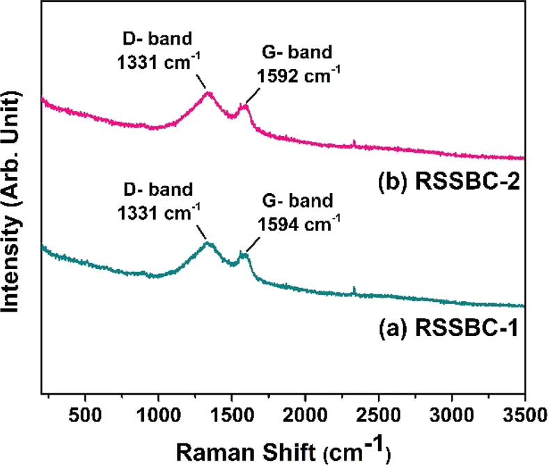 | ||
| Fig. 6 Raman spectra of (a) RSSBC-1 and (b) RSSBC-2 biochar samples, prepared from rubber seed shell biomass. | ||
The Raman spectra of both RSSBC-1 and RSSBC-2 biochar samples showed two prominent broad peaks at 1331 cm−1 and 1592–1594 cm−1. These peaks are characteristic of carbonaceous materials like biochar and are commonly referred to as the D-band and G-band, respectively.42 The D-band at 1331 cm−1 is associated with disordered or defective graphitic structures. It arises from the breathing modes of six-membered carbon rings and is activated by the presence of defects, edges, or heteroatoms in the graphitic structure. The intensity of the D-band is related to the degree of disorder in the carbon lattice.55,56 The G-band at 1592–1594 cm−1 corresponds to the in-plane stretching vibrations of the CC bonds in the graphitic layers. It is associated with the ordered, crystalline regions of the carbon structure. The position of the G-band is sensitive to the degree of graphitization, with a higher wavenumber indicating a more ordered and graphitic structure.56,57
The ID/IG ratio is a crucial parameter which reflects the relative intensities of the D-band (defect-induced) and G-band (graphitic) peaks.55,58 A higher ID/IG ratio indicates a greater degree of disorder and a higher density of defects within the carbon structure. The ID/IG ratios for RSSBC-1 and RSSBC-2 samples were found to be 1.22 and 1.23, respectively. These values suggest a moderate level of disorder in both biochar samples, with RSSBC-2 exhibiting a slightly higher defect density than RSSBC-1.
3.8. FESEM surface morphology analysis
One of the crucial parameters that needs to be investigated for characterizing any biochar sample is the surface morphology analysis, as it gives valuable information regarding the surface characteristics.59 Fig. 7 represents the surface morphology investigation of the prepared biochar samples in terms of SEM micrographs. Upon first glance, both the biochar samples appeared to be laden with pores. | ||
| Fig. 7 FESEM images and pore size (diameter) histogram of (a–c) RSSBC-1 and (d–f) RSSBC-2 biochar samples. | ||
The RSSBC-1 biochar sample has a corrugated surface structure, with smaller particles being attached sporadically (Fig. 7a). On the other hand, the RSSBC-2 sample has a more rigid and denser surface structure with a lesser number of smaller particles adhered within (Fig. 7d). The higher magnification of microscopic images revealed that the RSSBC-1 biochar sample exhibits greater surface roughness with pores of elliptical shapes (Fig. 7b). Conversely, the RSSBC-2 sample has lower surface roughness, although the shape of the pores resembles surface cracks (Fig. 7e). The type of reactor used for the pyrolysis of biomass clearly affected the surface morphology of the biochar. The pore diameter of the prepared biochar samples was measured using the imageJ software following the protocol of our previous study.60 The average pore diameter of RSSBC-1 (Fig. 7c) and RSSBC-2 (Fig. 7f) biochar samples was 0.98 ± 0.25 μm and 1.53 ± 0.68 μm, respectively (N = 65 in both cases).
3.9. Point of zero charge measurements
The point of zero charge (PZC) is the pH at which the net surface charge of an adsorbent, such as biochar, is zero. It is an important parameter that influences the adsorption behavior of charged species onto the adsorbent surface. The PZC value can vary depending on the properties of the biochar, such as the precursor material and the pyrolysis conditions.61 The result of the PZC measurement of the biochar samples carried out following the salt addition method is presented in Fig. 8. The RSSBC-2 sample showed a PZC value of 6.14, while the RSSBC-1 sample had a PZC of 7.65. This difference in PZC values suggests that the two biochars have different surface properties, which can be attributed to the variations in pyrolysis conditions between the two reactors.61 The PZC value indicates the pH at which the adsorbent surface is neutral. At pH values below the PZC, the surface of the adsorbent is positively charged, while at pH values above the PZC, the surface is negatively charged. This surface charge can influence the adsorption of charged species, such as ions or dyes, onto the biochar surface.62 The difference in PZC values between the two biochars suggests that they may exhibit different adsorption behaviors towards charged species, depending on the pH of the solution. RSSBC-1 biochar with a higher PZC (7.65) will have a positively charged surface at a wider range of pH values compared to the biochar with a lower PZC (6.14) and vice versa.63 The variation in PZC values between the two biochar samples prepared using different reactors can be attributed to differences in their surface properties, which may influence their adsorption performance towards charged species in aqueous solutions.64–66 | ||
| Fig. 8 Point of zero charge (PZC) measurements of RSSBC-1 and RSSBC-2 biochar samples. | ||
3.10. DLS hydrodynamic size and zeta potential measurements
The particle size of biochar is an important parameter that can affect its performance in various applications, such as soil amendment, water treatment, and carbon sequestration.67 The particle size measurements of the prepared biochar samples in terms of hydrodynamic diameter were carried out with the aid of the DLS technique and presented in Fig. 9. The RSSBC-1 sample, produced through the in-house built reactor, had an average hydrodynamic diameter of 115.23 nm. This relatively smaller hydrodynamic diameter of particles is likely due to the limited oxygen availability, specific design, and operating parameters of the in-house built reactor, which may have facilitated more efficient particle size reduction during the pyrolysis process. | ||
| Fig. 9 (a) Hydrodynamic diameter and (b) zeta potential measurements (at solution pH) of the prepared RSSBC-1 and RSSBC-2 biochar samples based on DLS technique. | ||
In contrast, the RSSBC-2 sample, produced in a pyrolytic reactor, had a larger average hydrodynamic diameter of 248.68 nm. The specific gas flow and heating conditions in the pyrolytic reactor may have led to larger particle sizes compared to the in-house built reactor used for RSSBC-1.17,68,69
Zeta potential analysis of biochar samples is essential as it provides crucial insights into the surface charge properties of biochar, which influence its interactions with other substances like water, nutrients, and contaminants. Understanding the zeta potential helps in assessing the biochar's adsorption capacity, colloidal stability, and its potential applications in soil improvement and environmental remediation.70,71 The zeta potential analysis of RSSBC-1 and RSSBC-2 samples reveals distinct differences in their surface charge properties, as can be seen from Fig. 9b. The RSSBC-1 sample exhibits two distinct peaks of zeta potential at −16.72 mV and +37.61 mV. This suggests that the biochar particles in this sample have a heterogeneous surface charge distribution, with some particles carrying a negative charge and others carrying a positive charge. This could be attributed to the presence of different functional groups on the surface of the biochar particles, which can influence their interactions with other particles or molecules.72,73 On the other hand, the RSSBC-2 sample shows a single zeta potential value of −14.91 mV. This indicates that the biochar particles in this sample have a more uniform negative surface charge. The negative zeta potential value suggests that the biochar particles are likely to repel each other, which can affect their aggregation behavior and interactions with other particles or molecules.74,75
The differences in surface charge properties of the biochar samples carry different implications for application. For example, the heterogeneous surface charge of RSSBC-1 may make it more suitable for certain environmental remediation applications, where the ability to interact with a wide range of contaminants is beneficial. On the other hand, the uniform negative surface charge of RSSBC-2 may make it more suitable for applications where particle aggregation needs to be minimized, such as in soil amendments or filtration systems.76
3.11. Surface area and porosity analysis
Aside from its chemical structure, the porosity-encompassing specific surface area and micro–mesopore structures are critical properties that significantly influence the performance of biochar samples, regardless of the application.42 The nitrogen adsorption–desorption isotherm of the RSSBC-1 and RSSBC-2 samples for estimating the specific surface area (SSA) is presented in Fig. 10a and b. | ||
| Fig. 10 Nitrogen adsorption–desorption isotherm and pore size distribution of RSSBC-1 (a and c) and RSSBC-2 (b and d) biochar samples. | ||
The RSSBC-1 sample had a higher adsorbed N2 gas amount of 89.22 cm3 g−1 at the initial relative pressure of 0.04, compared to 76.67 cm3 g−1 for the RSSBC-2 sample. This suggests that the in-house built reactor resulted in biochar with a higher initial adsorption capacity.77 As the relative pressure increased, the adsorbed N2 gas amount also increased for both samples, reaching 145.37 cm3 g−1 at 0.977 relative pressure for RSSBC-1 and 134.01 cm3 g−1 at 0.95 relative pressure for RSSBC-2. This indicates that both biochars have a high adsorption capacity at higher relative pressures.78 The desorption curves for both samples did not overlap with their respective adsorption curves, forming hysteresis loops. This behavior is typical of mesoporous materials and suggests that both biochars have a significant number of mesopores.79 At the lowest relative pressure during desorption, the curves did not merge with the adsorption curves for either sample. For RSSBC-1, the desorption curve ended at 97.13 cm3 g−1 adsorbed amount, while for RSSBC-2, it ended at 89.71 cm3 g−1. This suggests that both biochars have some irreversibly adsorbed N2 gas, likely due to the presence of micropores.80 The BET specific surface area was found to be higher for RSSBC-1 at 336.02 m2 g−1 compared to 299.09 m2 g−1 for RSSBC-2. This indicates that the in-house built reactor produced biochar with a higher surface area under the given pyrolysis conditions.
The BJH plots for pore size distribution for the RSSBC-1 and RSSBC-2 samples are presented in Fig. 10c and d. For the RSSBC-1 sample, the average pore diameter was 2.67 nm with a total pore volume of 0.2239 cm3 g−1. In comparison, the RSSBC-2 sample had an average pore diameter of 2.79 nm with a total pore volume of 0.2084 cm3 g−1. These findings indicate that both biochar samples possess mesopores with almost similar average pore diameters but slightly different total pore volumes. The micropore surface area was calculated following the t-plot method. The results of the nitrogen adsorption desorption study are compiled in Table 4.
| Parameter | Method | Unit | RSSBC-1 | RSSBC-2 |
|---|---|---|---|---|
| Specific surface area | BET | m2 g−1 | 336.02 | 299.09 |
| Average pore diameter | BJH | nm | 2.67 | 2.79 |
| Total pore volume | BJH | cm3 g−1 | 0.2239 | 0.2084 |
| Micropore surface area | t-plot | m2 g−1 | 262.15 | 213.18 |
| Macropore and mesopore surface area | t-plot | m2 g−1 | 73.87 | 85.91 |
| Micropore volume | t-plot | cm3 g−1 | 0.1259 | 0.1023 |
| Micropore area | t-plot | % | 78.02 | 71.28 |
According to the data presented in Table 4, the RSSBC-1 sample has a higher microporous surface area and a smaller pore diameter compared to the RSSBC-2 sample. These findings are consistent with the FESEM analysis, although the image-based pore size estimation was higher than the nitrogen adsorption desorption study. The pore size distribution data provides insights into the porous nature of the biochars, which is crucial for understanding their adsorption capabilities and potential applications in various fields.
3.12. Thermal stability analysis by TGA-DTG
Thermal stability analysis of bichar using TGA and DTG is crucial for understanding its decomposition behavior and suitability for high-temperature applications. These techniques provide insights into the thermal degradation of bichar, which is essential for developing materials that can maintain their properties under extreme conditions.81The TGA-DTG analysis of the prepared biochar samples are presented in Fig. 11. Both the biochar samples exhibited initial mass gain. The TGA analysis for RSSBC-1 (Fig. 11a) revealed that, initially up until 50 °C, 2.39% mass was gained, which was 4.94% for the RSSBC-2 sample. This suggests the adsorption of moisture by the biochar samples since they can absorb moisture from the environment depending on their preparation and storage conditions.82
 | ||
| Fig. 11 TGA and DTG analysis of (a) RSSBC-1 and (b) RSSBC-2 biochar samples. | ||
After the initial mass gain, there was a step of mass loss for the RSSBC-1 sample, which was about 1.34% at 136 °C and 0.17% at 100 °C for the RSSBC-2 sample. The subsequent mass loss can be attributed to the breakdown of various organic components within the biochar.17,83 Interestingly, there was a step of mass gain of about 0.39% up to 500 °C observed only for the RSSBC-2 sample. The subsequent slight increase in mass up to 500 °C could be linked to the transformation of organic matter into more stable carbon structures within the biochar. This phase of mass increase might indicate the formation of carbonaceous residues or the conversion of volatile components into more stable carbon compounds as the temperature rises.84 Further increase in temperature caused the loss of mass%, and the residual mass was 92.94% and 99.08% for the RSSBC-1 and RSSBC-2 samples, respectively. The distinct steps observed in the DTG curves of both samples suggest varying decomposition pathways during pyrolysis, possibly influenced by the reactor design and pyrolysis conditions.
4. Conclusion
This research work investigated the effect of reactor type on biochar properties. RSS biomass, a wood feedstock, was chosen for the preparation. RSSBC-1, biochar produced through an in-house built pyrolysis reactor, had distinct properties from RSSBC-2, biochar prepared through a commercial pyrolytic reactor. Although biochar yield was similar, there were some noteworthy changes in the properties of biochar:(i) Carbon and nitrogen content were higher for RSSBC-1, whereas hydrogen and oxygen content were higher for RSSBC-2. The O/C and (O + N)/C molar ratios were higher for the RSSBC-2, while the H/C was the same. Similar findings from the EDX analysis substantiated these results.
(ii) Surface composition analysis detected Mg as one of the impurities in both biochars where Mg exists as MgO or Mg(OH)2 by forming an Mg–O bond. Additionally, presence of Mg as MgCO3 in RSSBC-2 was also confirmed through the deconvoluted peak at 1307.23 eV. This was further substantiated by the detection of MgCO3 phase in the XRD pattern of RSSBC-2 sample.
(iii) The FTIR band at 1093 cm−1 for the RSSBC-2 was due to the presence of aromatic C–O stretching and phenolic –OH bending, which were absent in the RSSBC-1 sample.
(iv) Surface morphological analysis revealed differences in pore shape and size where RSSBC-1 has a smaller average pore diameter. This was bolstered by the findings from the N2 adsorption–desorption isotherm analysis. With a smaller average pore size, the RSSBC-1 possesses a higher surface area.
(v) The DLS average hydrodynamic diameter was higher for RSSBC-2, congruent with the findings from BET analysis. The zeta potential analysis revealed that RSSBC-1 exhibits two distinct peaks at −16.72 mV and +37.61 mV, whereas RSSBC-2 only showed potential at −14.91 mV. This suggests that particles of RSSBC-1 have a heterogeneous surface charge distribution compared to the RSSBC-2 sample.
(vi) The thermal stability of RSSBC-2 was higher than that of the RSSBC-1 sample, although a higher initial mass gain was observed in the RSSBC-2 sample.
The key findings of this research clearly indicate the differences in biochar properties due to the type of reactor used, while the temperature and stay time were kept the same. Biochar prepared in the in-house-built pyrolysis system showed promising properties as compared to biochar produced from commercial pyrolytic reactors, although this depends on the type of application.
Data availability
All the data used in this article will be available in the repository of BCSIR (Bangladesh Council of Scientific and Industrial Research), Bangladesh.Conflicts of interest
There are no conflicts to declare.Acknowledgements
This research work was supported by Bangladesh Council of Scientific and Industrial Research (BCSIR) through R&D project (ref. no. 39.02.0000.011.14.140.2021/1314; Date: 04/07/2022). We are thankful to Md. Farid Ahmed, IGCRT BCSIR; Mosharof Hossain, IERD, BCSIR; Sayed Farid Uddin Farhad, BCSIR Dhaka Laboratories; Dr, Samina Ahmed, IGCRT, BCSIR and Dr Shirin Akter Jahan, IGCRT, BCSIR for instrumental support.Notes and references
- S. P. Sohi, E. Krull, E. Lopez-Capel and R. Bol, Adv. Agron., 2010, 105, 47–82 CrossRef CAS
.
- FAQs, https://biocharinternational.org/about-biochar/faqs/, accessed May 21, 2024 Search PubMed.
- H. Bapat, S. E. Manahan and D. W. Larsen, Chemosphere, 1999, 39, 23–32 CrossRef CAS
- J. Lehmann and S. Joseph, Biochar for Environmental Management: Science, Technology and Implementation, Taylor & Francis, 2024 Search PubMed
- L. Zhao, X. Cao, O. Mašek and A. Zimmerman, J. Hazard Mater., 2013, 256, 1–9 Search PubMed
- J. W. Gabhane, V. P. Bhange, P. D. Patil, S. T. Bankar and S. Kumar, SN Appl. Sci., 2020, 2, 1307 CrossRef CAS
- J. Wang and S. Wang, J. Clean. Prod., 2019, 227, 1002–1022 CrossRef CAS
- S. Kloss, F. Zehetner, A. Dellantonio, R. Hamid, F. Ottner, V. Liedtke, M. Schwanninger, M. H. Gerzabek and G. Soja, J. Environ. Qual., 2012, 41, 990–1000 CrossRef CAS PubMed
- M. Bednik, A. Medyńska-Juraszek and I. Ćwieląg-Piasecka, Agronomy, 2022, 12, 1525 CrossRef CAS
- J. A. Ippolito, L. Cui, C. Kammann, N. Wrage-Mönnig, J. M. Estavillo, T. Fuertes-Mendizabal, M. L. Cayuela, G. Sigua, J. Novak, K. Spokas and N. Borchard, Biochar, 2020, 2, 421–438 CrossRef
- B. Bushra and N. Remya, Biomass Conv. Bioref., 2024, 14, 5759–5770 CrossRef
- G. Yang, Q. Hu, J. Hu, H. Yang, S. Yan, Y. Chen, X. Wang and H. Chen, Bioresour. Technol., 2023, 379, 129005 CrossRef CAS PubMed
- S.-L. Lin, H. Zhang, W.-H. Chen, M. Song and E. E. Kwon, Bioresour. Technol., 2023, 129588 CrossRef CAS PubMed
- M. Uchimiya, S. Hiradate and M. J. Antal, ACS Sustainable Chem. Eng., 2015, 3, 1642–1649 CrossRef CAS
- A. V. Bridgwater, Biomass Bioenergy, 2012, 38, 68–94 CrossRef CAS
- K. A. Spokas, K. B. Cantrell, J. M. Novak, D. W. Archer, J. A. Ippolito, H. P. Collins, A. A. Boateng, I. M. Lima, M. C. Lamb, A. J. McAloon, R. D. Lentz and K. A. Nichols, J. Environ. Qual., 2012, 41, 973–989 CrossRef CAS PubMed
- N. S. Pinky, M. B. Mobarak, S. Mustafi, M. Z. Rahman, A. Nahar, T. Saha and N. M. Bahadur, Arab. J. Chem., 2023, 105080 CrossRef CAS
- T. Suwunwong, N. Hussain, S. Chantrapromma and K. Phoungthong, Mater. Res. Express, 2020, 7, 015518 CrossRef CAS
- N. Mokti, A. Borhan, S. N. A. Zaine and H. F. Mohd Zaid, Processes, 2021, 9, 1161 CrossRef CAS
- A. S. Reshad, P. Tiwari and V. V. Goud, J. Energy Inst., 2018, 91, 940–950 CrossRef CAS
- C. Del Pozo, F. Rego, N. Puy, J. Bartrolí, E. Fàbregas, Y. Yang and A. V. Bridgwater, Waste Manage., 2022, 148, 106–116 CrossRef CAS PubMed
- O. Das, R. A. Mensah, G. George, L. Jiang, Q. Xu, R. E. Neisiany, K. Umeki, A. Phounglamcheik, M. S. Hedenqvist and Á. Restás, Biomass Bioenergy, 2021, 152, 106197 CrossRef CAS
- L. Ali, A. Palamanit, K. Techato, A. Ullah, M. S. Chowdhury and K. Phoungthong, Sustainability, 2022, 14, 3829 CrossRef CAS
- P. Cely, G. Gascó, J. Paz-Ferreiro and A. Méndez, J. Anal. Appl. Pyrol., 2015, 111, 173–182 CrossRef CAS
- A. S. Reshad, P. Tiwari and V. V. Goud, J. Therm. Anal. Calorim., 2017, 129, 577–592 CrossRef CAS
- K. Jindo, H. Mizumoto, Y. Sawada, M. A. Sanchez-Monedero and T. Sonoki, Biogeosciences, 2014, 11, 6613–6621 CrossRef
- C. E. Barquilha and M. C. Braga, Bioresour. Technol. Rep., 2021, 15, 100728 CrossRef CAS
- B. S. Giri, S. Gun, S. Pandey, A. Trivedi, R. T. Kapoor, R. P. Singh, O. M. Abdeldayem, E. R. Rene, S. Yadav and P. Chaturvedi, Bioengineered, 2020, 11, 743–758 CrossRef CAS PubMed
- M. B. Mobarak, N. S. Pinky, F. Chowdhury, M. S. Hossain, M. Mahmud, M. S. Quddus, S. A. Jahan and S. Ahmed, J. Saudi Chem. Soc., 2023, 101690 CrossRef
- A. Enders, K. Hanley, T. Whitman, S. Joseph and J. Lehmann, Bioresour. Technol., 2012, 114, 644–653 CrossRef CAS PubMed
- S. Li, S. Harris, A. Anandhi and G. Chen, J. Clean. Prod., 2019, 215, 890–902 CrossRef CAS
- K. S. Ro, K. B. Cantrell and P. G. Hunt, Ind. Eng. Chem. Res., 2010, 49, 10125–10131 CrossRef CAS
- V. K. Gupta, P. J. M. Carrott, M. M. L. Ribeiro Carrott and Suhas, Crit. Rev. Environ. Sci. Technol., 2009, 39, 783–842 CrossRef
- A. Aboulkas, H. Hammani, M. El Achaby, E. Bilal and A. Barakat, Bioresour. Technol., 2017, 243, 400–408 CrossRef CAS PubMed
- N. Mohamed Noor, A. Shariff and N. Abdullah, Iran. J. Energy Environ., 2012, 3(5), 60–65 Search PubMed
- P. Pariyar, K. Kumari, M. K. Jain and P. S. Jadhao, Sci. Total Environ., 2020, 713, 136433 CrossRef CAS PubMed
- C. Hadey, M. Allouch, M. Alami, F. Boukhlifi and I. Loulidi, Sci. World J., 2022, 2022(1), 2554475 Search PubMed
- K. A. Spokas, Carbon Manag., 2010, 1, 289–303 CrossRef CAS
- H. Zhang, Y. Cheng, Y. Zhong, J. Ni, R. Wei and W. Chen, Biochar, 2024, 6, 30 CrossRef CAS
- S. Wijitkosum and T. Sriburi, Heliyon, 2023, 9(9), e19831 CrossRef CAS PubMed
- G. Simões Dos Reis, C. Mayandi Subramaniyam, A. D. Cárdenas, S. H. Larsson, M. Thyrel, U. Lassi and F. García-Alvarado, ACS Omega, 2022, 7, 42570–42581 CrossRef PubMed
- M. González-Hourcade, G. S. dos Reis, A. Grimm, E. C. Lima, S. H. Larsson and F. G. Gentili, J. Clean. Prod., 2022, 348, 131280 CrossRef
- C. Yuan, M. Chen, K. Zhu, J. Ni, S. Wang, B. Cao, S. Zhong, J. Zhou and S. Wang, Fuel Process. Technol., 2022, 238, 107466 CrossRef CAS
- C. M. Ghimbeu, B. Zhang, A. M. de Yuso, B. Réty and J.-M. Tarascon, Carbon, 2019, 153, 634–647 CrossRef
- J. Yu, J.-S. Chang, H. Guo, S. Han and D.-J. Lee, Environ. Res., 2023, 235, 116592 CrossRef CAS PubMed
- Y. Yao, B. Gao, J. Chen and L. Yang, Environ. Sci. Technol., 2013, 47, 8700–8708 CrossRef CAS PubMed
- L. Luo, X. Yang, Z. Gao, X. Li, J. Xu, Y. Zhang, R. Deng, G. Huang, J. Wang and F. Pan, Electrochim. Acta, 2024, 478, 143815 CrossRef CAS
- M. Burachevskaya, T. Minkina, T. Bauer, I. Lobzenko, A. Fedorenko, M. Mazarji, S. Sushkova, S. Mandzhieva, A. Nazarenko and V. Butova, Sci. Rep., 2023, 13, 2020 CrossRef CAS PubMed
- M. L. Yeboah, X. Li and S. Zhou, Materials, 2020, 13, 625 CrossRef CAS PubMed
- D. Mohan, K. Abhishek, A. Sarswat, M. Patel, P. Singh and C. U. Pittman, RSC Adv., 2018, 8, 508–520 RSC
- B. Zhao and O. D. Nartey, in Proceedings of the World Congress on Advances in Civil, Environmental, and Materials Research, Busan, Republic of Korea, 2014, vol. 30, pp. 1–17 Search PubMed
- B. Armynah, Z. Djafar, W. H. Piarah and D. Tahir, J. Phys.: Conf. Ser., 2018, 979, 012038 CrossRef
- F. B. Reig, J. G. Adelantado and M. M. Moreno, Talanta, 2002, 58, 811–821 CrossRef CAS PubMed
- E. Pusceddu, A. Montanaro, G. Fioravanti, S. F. Santilli, P. U. Foscolo, I. Criscuoli, A. Raschi and F. Miglietta, Int. J. New Technol. Res., 2017, 3, 39–46 Search PubMed
- G. S. dos Reis, D. Bergna, A. Grimm, E. C. Lima, T. Hu, M. Naushad and U. Lassi, Colloids Surf., A, 2023, 669, 131493 CrossRef CAS
- G. S. dos Reis, S. H. Larsson, M. Thyrel, T. N. Pham, E. Claudio Lima, H. P. de Oliveira and G. L. Dotto, Coatings, 2021, 11, 772 CrossRef CAS
- R. Ji, Y. Wu, Y. Bian, Y. Song, Q. Sun, X. Jiang, L. Zhang, J. Han and H. Cheng, J. Hazard. Mater., 2021, 407, 124785 CrossRef CAS PubMed
- G. Huang, Y. Liu, X. Wu and J. Cai, New Carbon Mater., 2019, 34, 247–257 CrossRef CAS
- Y. Tao, W. Feng, Z. He, B. Wang, F. Yang, A. I. Nafsun and Y. Zhang, Environ. Sci. Eur., 2024, 36, 79 CrossRef
- M. Bin Mobarak, Md. S. Hossain, F. Chowdhury and S. Ahmed, Arab. J. Chem., 2022, 15, 104117 CrossRef CAS
- S. Neusatz Guilhen, T. Watanabe, T. Tieko Silva, S. Rovani, J. Takehiro Marumo, J. Alberto Soares Tenório, O. Mašek and L. Goulart de Araujo, Recent Prog. Mater., 2022, 4, 1–30 CrossRef
- E. A. Al-Maliky, H. A. Gzar and M. G. Al-Azawy, in IOP Conference Series: Materials Science and Engineering, IOP Publishing, 2021, vol. 1184, p. 012004 Search PubMed
- M. Kosmulski, Adv. Colloid Interface Sci., 2023, 102973 CrossRef CAS PubMed
- A. I. Osman, E. M. A. El-Monaem, A. M. Elgarahy, C. O. Aniagor, M. Hosny, M. Farghali, E. Rashad, M. I. Ejimofor, E. A. López-Maldonado, I. Ihara, P.-S. Yap, D. W. Rooney and A. S. Eltaweil, Environ. Chem. Lett., 2023, 21, 2337–2398 CrossRef CAS
- H. Nath, A. Saikia, P. J. Goutam, B. K. Saikia and N. Saikia, Bioresour. Technol. Rep., 2021, 14, 100689 CrossRef CAS
- Q. Ge, P. Li, M. Liu, G. Xiao, Z. Xiao, J. Mao and X. Gai, Bioresour. Bioprocess., 2023, 10, 51 CrossRef PubMed
- I. G. Edeh and O. Mašek, Eur. J. Soil Sci., 2022, 73, e13138 CrossRef CAS
- H. Huang, N. G. Reddy, X. Huang, P. Chen, P. Wang, Y. Zhang, Y. Huang, P. Lin and A. Garg, Sci. Rep., 2021, 11, 7419 CrossRef CAS PubMed
- M. Garcia-Perez, T. Lewis and C. E. Kruger, Part, 2010, 1, 137 Search PubMed
- E. M. Batista, J. Shultz, T. T. Matos, M. R. Fornari, T. M. Ferreira, B. Szpoganicz, R. A. de Freitas and A. S. Mangrich, Sci. Rep., 2018, 8, 10677 CrossRef PubMed
- M. Hong, L. Zhang, Z. Tan and Q. Huang, Environ. Sci. Pollut. Res., 2019, 26, 19738–19748 CrossRef CAS PubMed
- P. Zhang, W. Duan, H. Peng, B. Pan and B. Xing, ACS Environ. Au, 2022, 2, 115–127 CrossRef CAS PubMed
- Y. Yang, Y. Piao, R. Wang, Y. Su, N. Liu and Y. Lei, J. Hazard. Mater, 2022, 8, 100171 CrossRef CAS
- A. K. Chaubey, T. Pratap, B. Preetiva, M. Patel, J. S. Singsit, C. U. Pittman and D. Mohan, ACS Omega, 2024, 3c07804 CrossRef PubMed
- W. Yang, J. Shang, B. Li and M. Flury, Crit. Rev. Environ. Sci. Technol., 2020, 50, 2484–2522 CrossRef CAS
- A. Mukherjee, A. R. Zimmerman and W. Harris, Geoderma, 2011, 163, 247–255 CrossRef CAS
- O. Tomin, R. Vahala and M. R. Yazdani, Heliyon, 2024, 10(2), e24722 CrossRef CAS PubMed
- D. A. Roberts, N. A. Paul, S. A. Dworjanyn, M. I. Bird and R. de Nys, Sci. Rep., 2015, 5, 9665 CrossRef CAS PubMed
- Z. A. Alothman, Materials, 2012, 5, 2874–2902 CrossRef CAS
- K. Morishige, ACS Omega, 2021, 6, 15964–15974 CrossRef CAS PubMed
- S. Elkhalifa, O. Elhassan, P. Parthasarathy, H. Mackey, T. Al-Ansari and G. McKay, in Computer Aided Chemical Engineering, Elsevier, 2020, vol. 48, pp. 1543–1548 Search PubMed
- W. Feng, T. Wang, F. Yang, R. Cen, H. Liao and Z. Qu, Environ. Sci. Eur., 2023, 35, 66 CrossRef CAS
- P. K. Ghodke, A. K. Sharma, J. K. Pandey, W.-H. Chen, A. Patel and V. Ashokkumar, J. Environ. Manage., 2021, 298, 113450 CrossRef CAS PubMed
- N. Hossain, S. Nizamuddin, G. Griffin, P. Selvakannan, N. M. Mubarak and T. M. I. Mahlia, Sci. Rep., 2020, 10, 1–15 CrossRef PubMed
| This journal is © The Royal Society of Chemistry 2024 |