 Open Access Article
Synthesis of MoS2/MoO3 nano-heterojunction towards enhanced photocatalytic activity under LED light irradiation via in situ oxidation sintering†
Jianfeng Qiu ab,
Yanping Liub,
Minxian Caob,
Luqi Xieb,
Yongkun Liub,
Hongwen Lib,
Junqiang Lub,
Qifeng Liangb,
Jiaqi Pan
 ac and
Chaorong Li*a
aCollege of Textile Science and Engineering, Zhejiang Sci-Tech University, Hangzhou, 310018, P. R. China. E-mail: crli@zstu.edu.cn
bDepartment of Physics, Shaoxing University, Shaoxing, 312000, P. R. China
cKey Laboratory of Optical Field Manipulation of Zhejiang Province, Department of Physics, Zhejiang Sci-Tech University, Hangzhou, 310018, P. R. China
First published on 29th October 2024
Abstract
The MoS2/MoO3 nano-heterojunction photocatalyst was synthesized via the in situ oxidation sintering method. The properties of the samples were characterized by XRD, SEM, EDX, TEM, UV-vis, PL, FT-IR, BET and electrochemical techniques. The MoS2/MoO3 nano-heterojunction (MS-400) exhibited significantly better photocatalytic activity toward Rhodamine B degradation (0.42634 h−1) than monomer MoS2 (∼8.0-folds) and MoO3 (∼25.6-folds). This is mainly attributed to the MoS2/MoO3 heterojunction interface having an appropriate potential gradient that can promote the interface carrier transportation/separation to optimize the carrier efficiency and increase the solar absorption and specific surface areas/active sites via microstructures.
1. Introduction
With the increasing concern over environmental degradation, the use of semiconductor photocatalysts to degrade organic pollutants in water has been rapidly developed in recent years.1–5 It has been shown that heterogeneous photocatalytic oxidation based on oxides is one of the most promising methods for the treatment of water pollutants due to its suitable potential structure for pollutant oxidation and its excellent stability for long-term applications.6–10 However, solar energy is inefficient because of the wider bandgap and the high carrier recombination, limiting its further commercialization. Therefore, the light absorption and carrier efficiency must be developed so that the drawbacks of most oxides can be overcome.11,12 So far, semiconductor photocatalysts, such as Ag-based,13–15 Bi2WO6-based16,17 and g-C3N4-based photocatalysts,18,19 have been reported to exhibit remarkable visible photocatalytic activity.Notably, molybdenum (Mo) oxides and sulfides have attracted growing research interest as promising electrocatalysts and photocatalysts owing to their unique electronic structures and surface active sites. They are even being explored as photo-electrocatalysts for a variety of applications in addressing environmental and energy issues.20–22 Molybdenum sulfide (MoS2) is a well-studied semiconductor with superior catalytic properties and stability and is extensively used as active materials in photo-electrocatalysis, sensors, supercapacitors and lithium ion batteries. In particular, the few-layered 2H-MoS2, as a n-type semiconductor, possesses unique optical properties such as a layer-modulated narrow band gap,23 strong light–matter interaction,24 and anti-photocorrosion25,26 and has been illustrated to be a better catalyst for visible-light-driven photocatalysis, e.g., CuS/MoS2,27 Au/MoS2,28 Ag/MoS2 (ref. 29) and MoS2/graphene.30 In addition, the few-layered MoS2 with sufficient surface areas and edges can provide numerous active sites. It can also promote carrier diffusion and decrease the overpotential for accelerating the photocatalytic process.31 However, as a monomer photocatalyst, the high carrier recombination and low carrier mobility have restricted its further applications. Thus, further improvement would be necessary, such as surface modification, doping, or barrier regulation. As reported previously, for a heterojunction, the electric field force caused by an intrinsic built-in electric field can rapidly drive the transfer and separation of electrons and holes, forming a region of space charge that enhances the carrier concentration and mobility for effectively improving the carrier. This development opens up new avenues for solar-driven photocatalytic water splitting and wastewater treatment, offering sustainable solutions for generating clean energy and addressing water pollution challenges.
Matched heterojunction materials are clearly important. Molybdenum trioxide (MoO3), as an intrinsic n-type semiconductor, possesses a suitable band gap of approximately 2.89 eV, matched crystalline structure and homologous Mo-based compound.32 MoO3 is deemed as one of the most matched layered transition-metal oxides to form a surface heterojunction, showing high stability and high-quality,33 including for use as an interconnection layer for polymer tandem solar cells or pseudocapacitors.34,35 Moreover, the surface MoO3-based heterojunction modification with remarkable light absorption can further enhance the solar efficiency, as well as provide a mass of activated carrier injection caused by Mo6+ ions for improving the carrier efficiency.36,37 Furthermore, the good physical–chemical stability can effectively enhance the photocatalytic stability for actual applications.38–40
In this work, we discover the novel photocatalyst MoS2/MoO3 type II heterojunction41,42 using the simple in situ oxidation sintering method. Significantly, molybdenum oxide and molybdenum sulfide share the same Mo-based cation, providing a more intimate heterojunction interface in the formed type II heterojunction for accelerating the carrier separation and inhibiting recombination. Furthermore, a series of characteristics were detected by SEM, HRTEM, XPS, among other methods. The results clearly showed that the obtained MoS2/MoO3 heterojunction (MS-400) had excellent photocatalytic activity toward Rhodamine B degradation under LED light irradiation.
2. Experimental
All of the reagents were used directly without further purification after purchase. Molybdenum disulfide (MoS2, 99.5%) was purchased from Shanghai Aladdin Biochemical Technology Co., Ltd (Shanghai, China). A weighed mass of 0.5 g MoS2 was added to the bottom of an alundum crucible. It was then placed into a muffle furnace, heated at a rate of 5 °C min−1 in air, and kept at a certain temperature for 1 h. Subsequently, the sample was cooled to room temperature naturally, and the holding temperature was changed. The samples obtained at different sintering temperatures were respectively named MS-300, MS-350, MS-400, MS-450, MS-500 and MS-600, and the original molybdenum disulfide was labelled as MS-0.Further details and characterizations are shown in ESI.†
3. Results and discussion
3.1 Structure of the photocatalyst
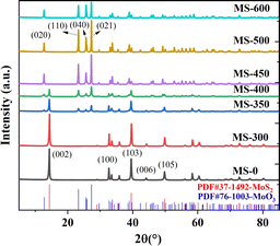
The XRD pattern is shown in Fig. 1. The diffraction patterns for MS-0 and MS-300 exhibit sharp and intense peaks at 14.38°, 32.68°, 39.54°, 44.15° and 49.79°, corresponding to the (002), (100), (103), (006) and (105) planes of MoS2 (JPCDS 37-1492), respectively. This indicates that the in situ oxidation process does not occur before 300 °C. With the increase of sintering temperature, the new diffraction peaks at 12.72°, 23.28°, 25.69° and 27.28° clearly correspond to MoO3 (JPCDS 76-1003), indicating the proceeding of the in situ oxidation process. Correspondingly, the peaks of MoS2 gradually diminish. These results correspond with the Raman and FTIR spectral information shown in Fig. S1 and S2,† respectively. The grain size of the sample by Scherrer formula is also consistent with it (Fig. S3†). It is worth noting that the mass also begins to decrease with the increased temperature (Table S1†). Furthermore, the color of the sample gradually changed from black to white (Fig. S4†), i.e., the microstructure begins to change at 350 °C. With the sintering temperature further increasing, the in situ oxidation process for MS-600 is thoroughly accomplished. Thus, all of the peaks are ascribed to MoO3. These results confirm that the MoS2/MoO3 heterojunction was successfully obtained.Scanning electron microscopy (SEM) was utilized to examine the morphology and size of the prepared catalysts. Fig. 2 displays representative morphologies of the synthesized nanocatalysts. MoS2 (MS-0) exhibits a typical stratified structure (Fig. 2a). However, MoO3 (MS-600) shows the typical plate-shaped morphology (Fig. 2g). The average size estimate is ∼2–5 μm, and is obviously much bigger than the former. As shown in Fig. 2b–f, the formed composites exhibit a gradual change process, corresponding to the characteristics of the monomer MoS2 and monomer MoO3. Interestingly, the obtained MoS2/MoO3 heterojunction (MS-400) still maintained a lamellar structure that was similar to MoS2, exhibiting good structural stability. The specific surface area of the MoS2/MoO3 heterojunction (MS-400) is 5.9375 m2 g−1, which is more than twice as much as that for MO-0 (2.7417 m2 g−1), providing sufficient specific surface areas and active sites for photocatalysis (Fig. S5†). It corresponds with the grain size (Fig. S3†).
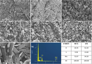 | ||
| Fig. 2 SEM images of the samples. (a–g) SEM images of MS-0, MS-300, MS-350, MS-400, MS-450, MS-500 and MS-600. (h) The EDS of MS-400. | ||
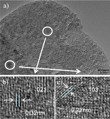
The TEM and HRTEM images of the MS-400 nano-composite are displayed in Fig. 3. As shown in Fig. 3a, the MoO3 layers appear at the outer surface of the MoS2 crystal. The obvious boundary indicates the presence of a heterostructure and formation via the in situ oxidation process. In HRTEM, the observed lattice spacing of 0.32 nm clearly corresponds to the (021) planes of MoO3 (JPCDS 76-1003, Fig. 3b), and the lattice spacing of 0.22 nm corresponds to the (103) plane of MoS2 (JPCDS 37-1492, Fig. 3c). These results confirm that MoO3 has been successfully combined with MoS2, forming a heterojunction between MoS2 and MoO3 through in situ oxidation.
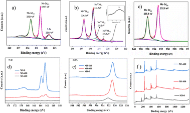
The chemical state of the samples was carried out using X-ray photoelectron spectroscopy (XPS) measurement. The typical XPS of MS-0, MS-400 and MS-600 are illustrated in Fig. 4. All peaks were calibrated by the C 1s peak at 284.6 eV. Elements of Mo, S, O and adventitious C existed in the MS-0, MS-400 and MS-600 composites (Fig. 4f). High-resolution spectra of Mo 3d (MS-0) are shown in Fig. 4a. Two bands at 229.7 and 232.9 eV are ascribed to the Mo4+ 3d5/2 and 3d3/2 binding energies, respectively.43 The Mo 3d5/2 and Mo 3d3/2 binding energies for MS-600 are observed at 232.8 and 235.9 eV, respectively, and ascribed to Mo6+ (Fig. 4c).44 Thus, the Mo4+/Mo6+ mixed state can be observed in Fig. 4b, and confirms that the MoS2/MoO3 heterojunction was successfully obtained. The XPS spectra of S 2p and O 1s for MS-0, MS-400 and MS-600 were also obtained. As shown in Fig. 4d, the decreased S 2p manifests the continuously in situ oxidation process, i.e., MoS2 gradually converts into MoO3. It can also be supported by Fig. 4e; i.e., the major peak of O 1s obviously increases with the decreased S 2p. However, O 1s can also be observed in MS-0, which is ascribed to the hydroxyl group from the surface absorbed water, and exhibits an obvious shift that is different from that in MoO3. All these observations manifest the fabrication of the MoS2/MoO3 heterojunction via in situ oxidation process.
3.2 Photocatalytic performance
The photocatalytic activity of the samples for the degradation of Rhodamine B under LED light is shown in Fig. 5. As shown in Fig. 5a, with increasing sintering temperature, the photocatalytic degradation performance of the samples clearly increases (MS-0-400), and then decreases (MS-450-600). Herein, MS-0 (MoS2) and MS-600 (MoO3) exhibit lower intrinsic photocatalytic activities, while MS-400 exhibits the best activity, i.e., the degradation reaches ∼56% after 2.5 h under LED light. This indicates that the formation of a heterojunction would be the core issue for photocatalysis. The first order kinetic plots of the samples were performed and are shown in Fig. 5b. The obtained results show that the RhB degradation of the formed heterojunction (MS-400) exhibited 8.0-fold (MS-0)/25.6-fold (MS-600) enhancement when compared to the monomer.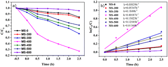 | ||
| Fig. 5 (a) Photodegradation efficiency of RhB and (b) the photocatalytic kinetic curves of the RhB degradation. | ||
3.3 Optical properties of photocatalyst
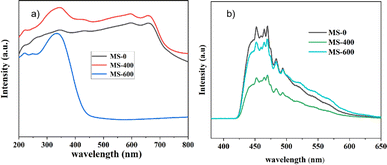
Ultraviolet-visible diffuse reflectance spectra (UV-Vis DRS) were used to evaluate the optical properties of the as-prepared samples (Fig. 6a). The sample labeled MS-600 exhibits an absorption edge at around ∼450 nm, corresponding to a band gap (Eg) of ∼2.75 eV for MoO3.45 For MS-0, the absorption edge around ∼700 nm manifests a band gap of ∼1.77 eV for MoS2. Due to the unique surface state caused by mixed MoS2 and MoO3, MS-400 shows stronger light absorption than MS-0, which is also the reason for the enhanced photocatalytic performance. However, the slight increase in the light absorption causes a remarkable photocatalytic enhancement, indicating the important role of the formed type II heterojunction.The photoluminescence (PL) spectra of MS-0, MS-400 and MS-600 are displayed in Fig. 6b. The as-prepared samples exhibit a series of peaks at around ∼450–480 nm, which is from the recombination of the photo-generated electron and hole pairs.46 Significantly, compared with MS-0 and MS-600, the PL emission intensity of MS-400 displayed a significant decrease. This suggests that the recombination rate of the photogenerated electron–hole pairs has been effectively suppressed through the formation of a type II heterojunction structure between MoS2 and MoO3. The efficient separation of the photo-generated electron hole pairs leads to enhanced photocatalytic degradation performance, which is consistent with the observed photocatalytic activity of the MS-400 sample.
3.4 Photo-electrochemical measurements of samples
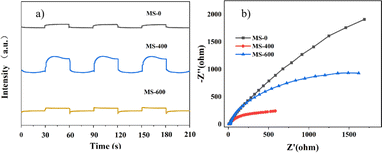
The transient photocurrent responses of MS-0, MS-400 and MS-600 were recorded via several on–off cycles of irradiation, as evidence of the activity. MS-400 clearly shows the best photocurrent under light irradiation, in comparison with MS-0 (MoS2) and MS-600 (MoO3).The behavior of the photocurrent matches well with the on and off switching of the illumination (Fig. 7a). Electrochemical impedance spectroscopy (EIS) is regarded as an effective approach for investigating the charge transfer process at the interfacial contact,47 i.e., the arc radius of the EIS Nyquist plot reflects the reaction rate occurring at the interface. As shown in Fig. 7b, the arc radius of MS-400 is smaller than that of MS-0 and MS-600 under light irradiation, indicating that MS-400 exhibited a faster interfacial charge transfer and the most efficient separation of the photogenerated charge carriers. Both results indicate the remarkable optimization of the carrier behaviors, which are beneficial for enhancing photocatalysis.
3.5 Possible photocatalytic mechanism
According to the above discussion, a proposed mechanism is discussed to explain the enhanced photocatalytic activity and stability of the MoS2/MoO3 type II heterostructure under led light irradiation. In this work, the MoO3 molecule covered the surface of MoS2 to form the heterojunction. Subsequently, owing to the existence and effect of the built-in electrical potential in the heterostructure, a large amount of electron hole (e−–h+) pairs are generated under led light irradiation after the absorption of photons via the well-connected interface. Thus, the rapid and effective separation of the electron–hole pairs was accomplished. The electrons accumulating on the surface of MoO3 will directly reduce the dye molecules, or react with O2 at the surface of the photocatalyst in the solution to form ˙O2−, which could also oxidize the dyes. Furthermore, the holes react directly with the dye or with the water on the catalyst surface to form ˙OH, and then participate in the oxidative degradation of the dye.Based on the above discussion, the formed MoS2/MoO3 heterojunction exhibits decent photocatalytic activities in RhB degradation, owing to the increased specific surface areas/active sites and increased light absorption, including the carrier transportation and separation.
4. Conclusions
In conclusion, a novel MoS2/MoO3 type II heterojunction nano-catalyst was successfully synthesized via a simple in situ oxidation sintering method. The MoS2/MoO3 heterojunction exhibits significantly enhanced photocatalytic activity compared to monomer MoS2 (MS-0, ∼8.7-folds) and monomer MoO3 (MS-600, ∼31.5-folds). The improvement of the photocatalytic activity can be mainly ascribed to the existence of a built-in electric field from the MoS2/MoO3 type II heterojunction, which can regulate the carrier behavior efficiently to promote the photocatalysis, including the transportation and separation of photogenerated electron and hole pairs, as well as increasing the solar absorption and specific surface areas/active sites via microstructure. Thus, this nano-photocatalyst prepared via in situ oxidation can provide new insights for the energy-environment field.Data availability
The data supporting this article have been included as part of the ESI.†Conflicts of interest
There are no conflicts to declare.Acknowledgements
This work was supported by the National Natural Science Foundation of China (Grant No. 51672249, 51802282, 11804301 and 22066024).Notes and references
- G. Lin and X. Xu, ACS Sustain. Chem. Eng., 2020, 8, 9641–9649 CrossRef CAS.
- H. Liu, J. Wang, O. Odunmbaku, P. Xia, L. Liu, Q. Chang, Y. Huang, X. lin, J. Yang, Z. Shang, Z. Ye, M. Li and J. Qiu, Sep. Purif. Technol., 2023, 320, 124142 CrossRef CAS.
- X. Ren, M. Guo, L. Xue, L. Xu, L. Li, L. Yang, M. Wang, Y. Xin, F. Ding and Y. Wang, Appl. Surf. Sci., 2023, 630, 157446 CrossRef CAS.
- C. Zhang, L. Wang, F. Yuan, R. Meng, J. Chen, W. Hou and H. Zhu, Appl. Surf. Sci., 2020, 534, 147544 CrossRef CAS.
- A. Singh, S. S. Shah, C. Sharma, V. Gupta, A. K. Sundramoorthy, P. Kumar and S. Arya, J. Environ. Chem. Eng., 2024, 12, 113032 CrossRef CAS.
- V. Vaiano, G. Iervolino, D. Sannino, L. Rizzo, G. Sarno and A. Farina, Appl. Catal., B, 2014, 160, 247–253 CrossRef.
- H. Wang, X. Huang, W. Li, J. Gao, H. Xue, R. K. Y. Li and Y.-W. Mai, Colloids Surf., A, 2018, 549, 205–211 CrossRef CAS.
- W. G. Wang, J. G. Yu, Q. J. Xiang and B. Cheng, Appl. Catal., B, 2012, 119, 109–116 CrossRef.
- Y. F. Zhang, S. S. He, Z. L. He, Y. C. Zhang, Y. P. Feng, Y. L. Wang and M. Zhang, Int. J. Electrochem. Sci., 2022, 17, 13 Search PubMed.
- M. Thakur, A. Singh, A. Dubey, A. K. Sundramoorthy, P. Kumar and S. Arya, Emerg. Mater., 2024, 7, 1805–1817 CrossRef CAS.
- K. Chawraba, H. Medlej, A. Noun, M. Sakr, J. Toufaily, J. Lalevee and T. Hamieh, Chemistryselect, 2024, 9, 13 CrossRef.
- B. Singh, A. Singh, A. Sharma, P. Mahajan, S. Verma, B. Padha, A. Ahmed and S. Arya, J. Mol. Struct., 2022, 1255, 132379 CrossRef CAS.
- A. Singh, A. Ahmed, A. Sharma, C. Sharma, S. Paul, A. Khosla, V. Gupta and S. Arya, Phys. B, 2021, 616, 413121 CrossRef CAS.
- A. Dubey, A. Singh, A. Sharma, A. K. Sundramoorthy, R. Mahadeva, V. Gupta, S. Dixit and S. Arya, Appl. Phys. A, 2023, 129, 692 CrossRef CAS.
- M. Bhagat, R. Anand, R. Datt, V. Gupta and S. Arya, J. Inorg. Organomet. Polym. Mater., 2019, 29, 1039–1047 CrossRef CAS.
- M. T. L. Lai, K. M. Lee, T. C. K. Yang, C. W. Lai, C.-Y. Chen, M. R. Johan and J. C. Juan, J. Alloys Compd., 2023, 953, 169834 CrossRef CAS.
- A. Xiakeer, L. Wang, M. Maimaiti, M. Jiang, X. Feng and Y. Zhang, Ceram. Int., 2024, 50, 2680–2688 CrossRef CAS.
- Y. H. Fu, W. Liang, J. Q. Guo, H. Tang and S. S. Liu, Appl. Surf. Sci., 2018, 430, 234–242 CrossRef CAS.
- J. W. Fu, Q. L. Xu, J. X. Low, C. J. Jiang and J. G. Yu, Appl. Catal., B, 2019, 243, 556–565 CrossRef CAS.
- Z. Tang, L. Xu, K. Shu, J. Yang and H. Tang, Colloids Surf., A, 2022, 642, 128686 CrossRef CAS.
- Y. Yuan, R.-t. Guo, L.-f. Hong, X.-y. Ji, Z.-s. Li, Z.-d. Lin and W.-g. Pan, Colloids Surf., A, 2021, 611, 125836 CrossRef CAS.
- S. Dutt, A. Singh, R. Mahadeva, A. K. Sundramoorthy, V. Gupta and S. Arya, Diamond Relat. Mater., 2024, 141, 110554 CrossRef CAS.
- R. Yang, Y. Fan, Y. Zhang, L. Mei, R. Zhu, J. Qin, J. Hu, Z. Chen, Y. Hau Ng, D. Voiry, S. Li, Q. Lu, Q. Wang, J. C. Yu and Z. Zeng, Angew. Chem., Int. Ed., 2023, 62, 13 Search PubMed.
- L. Britnell, R. M. Ribeiro, A. Eckmann, R. Jalil, B. D. Belle, A. Mishchenko, Y.-J. Kim, R. V. Gorbachev, T. Georgiou, S. V. Morozov, A. N. Grigorenko, A. K. Geim, C. Casiraghi, A. H. Castro Neto and K. S. Novoselov, Science, 2013, 340, 1311–1314 CrossRef CAS.
- F. Jamal, A. Rafique, S. Moeen, J. Haider, W. Nabgan, A. Haider, M. Imran, G. Nazir, M. Alhassan, M. Ikram, Q. Khan, G. Ali, M. Khan, W. Ahmad and M. Maqbool, ACS Appl. Nano Mater., 2023, 6, 7077–7106 CrossRef CAS.
- W. K. Jo and N. C. S. Selvam, Appl. Catal., A, 2016, 525, 9–22 CrossRef CAS.
- N. N. Meng, Y. F. Zhou, W. Y. Nie, L. Y. Song and P. P. Chen, J. Nanopart. Res., 2015, 17, 10 CrossRef.
- L. Yang, S. H. Guo and X. H. Li, J. Alloys Compd., 2017, 706, 82–88 CrossRef CAS.
- A. Nazneen, M. I. Khan, M. A. Naeem, M. Atif, M. Iqbal, N. Yaqub and W. A. Farooq, J. Mol. Struct., 2020, 1220, 6 CrossRef.
- Y. Yuan, P. F. Shen, Q. J. Li, G. Chen, H. F. Zhang, L. Y. Zhu, B. Zou and B. B. Liu, J. Alloys Compd., 2017, 700, 12–17 CrossRef CAS.
- D. Voiry, J. Yang and M. Chhowalla, Adv. Mater., 2016, 28, 6197–6206 CrossRef CAS PubMed.
- S. Balendhran, S. Walia, H. Nili, J. Z. Ou, S. Zhuiykov, R. B. Kaner, S. Sriram, M. Bhaskaran and K. Kalantar-zadeh, Adv. Funct. Mater., 2013, 23, 3952–3970 CrossRef CAS.
- Z. Wei and S. Zhuiykov, Nanoscale, 2019, 11, 15709–15738 RSC.
- J. Liu, S. Shao, G. Fang, J. Wang, B. Meng, Z. Xie and L. Wang, Sol. Energy Mater. Sol. Cells, 2014, 120, 744–750 CrossRef CAS.
- T. Brezesinski, J. Wang, S. H. Tolbert and B. Dunn, Nat. Mater., 2010, 9, 146–151 CrossRef CAS PubMed.
- X. Xue, J. Zhang, I. A. Saana, J. Sun, Q. Xu and S. Mu, Nanoscale, 2018, 10, 16531–16538 RSC.
- J. F. Qiu, J. Q. Pan, S. H. Wei, Q. F. Liang, Y. W. Wang, R. Wu and C. R. Li, RSC Adv., 2021, 11, 38523–38527 RSC.
- Z. L. Huang, J. C. Liu, S. Zong, X. Y. Wang, K. X. Chen, L. L. Liu and Y. X. Fang, J. Colloid Interface Sci., 2022, 606, 848–859 CrossRef CAS PubMed.
- M. K. Hussain and N. R. Khalid, J. Mol. Liq., 2022, 346, 11 Search PubMed.
- M. K. Hussain, N. R. Khalid, M. B. Tahir, M. Tanveer, T. Iqbal and M. Liaqat, Mater. Sci. Semicond. Process., 2023, 155, 11 CrossRef.
- T. Liu, J. Huang, Z. Huang, Q. Luo, H. Wu, Y. Meng, C. He and H. Li, Chem. Eng. J., 2024, 486, 150209 CrossRef CAS.
- Z. Huang, J. Huang, T. Liu, Y. Wen, H. Wu, S. Yang and H. Li, Chem. Eng. J., 2024, 485, 149987 CrossRef CAS.
- S. W. Hu, L. W. Yang, Y. Tian, X. L. Wei, J. W. Ding, J. X. Zhong and P. K. Chu, Appl. Catal., B, 2015, 163, 611–622 CrossRef CAS.
- H. D. Li, W. J. Li, X. T. Liu, C. J. Ren, F. Z. Wang and X. Miao, J. Taiwan Inst. Chem. Eng., 2018, 89, 86–94 CrossRef CAS.
- J. Ma, Q. Liu, L. Zhu, J. Zou, K. Wang, M. Yang and S. Komarneni, Appl. Catal., B, 2016, 182, 26–32 CrossRef CAS.
- W. Zhang, S.-c. Li, M. Yan, L. Li, J. Ma, J. Wang, C. Liu and Y. Bao, J. Environ. Chem. Eng., 2022, 10, 108418 CrossRef CAS.
- W. Teng, X. Li, Q. Zhao and G. Chen, J. Mater. Chem. A, 2013, 1, 9060–9068 RSC.
Footnote |
| † Electronic supplementary information (ESI) available. See DOI: https://doi.org/10.1039/d4ra05673f |
| This journal is © The Royal Society of Chemistry 2024 |

