 Open Access Article
Reversible Zn and Mn deposition in NiFeMn-LDH cathodes for aqueous Zn–Mn batteries
Yuan Ge ab,
Dong Pan*c,
Lin Liab,
Jiaxin Fanb and
Wei Liud
aSchool of Chemical Engineering and Technology, China University of Mining and Technology, Xuzhou 221116, People's Republic of China. E-mail: geyuan@lpssy.edu.cn
bSchool of Chemistry and Materials Engineering, Liupanshui Normal University, Liupanshui, Guizhou 553000, People's Republic of China
cSchool of Mining and Mechanical Engineering, Liupanshui Normal University, Liupanshui, Guizhou 553000, People's Republic of China. E-mail: pandong@lpssy.edu.cn
dCRRC Qingdao Sifang Rolling Stock Research Insititute Co Ltd, People's Republic of China
First published on 8th November 2024
Abstract
Introducing NiFeMn-Layered Double Hydroxide (LDH) as an innovative cathode material for Zn–Mn batteries, this study focuses on bolstering the electrochemical efficiency and stability of the system. We explored the effect of varying Zn/Mn molar ratio in the electrolyte on the battery's electrochemical performance and investigated the underlying reaction mechanism. Our results show that an electrolyte Zn/Mn molar ratio of 4![[thin space (1/6-em)]](https://www.rsc.org/images/entities/char_2009.gif) :
:![[thin space (1/6-em)]](https://www.rsc.org/images/entities/char_2009.gif) 1 achieves a balance between capacity and stability, with an areal capacity of 0.20 mA h cm−2 at a current of 0.2 mA and a capacity retention rate of 53.35% after 50 cycles. The mechanism study reveals that during the initial charge–discharge cycle, NiFeMn–CO3 LDH transforms into NiFeMn–SO4 LDH, which then absorbs Zn2+, Mn2+, and SO42− ions to form a stable composite substrate. This substrate enables the reversible deposition–dissolution of Mn ions, while Zn ions participate in the reaction continuously, with most Mn- and Zn-containing compounds depositing in an amorphous phase. Although further optimization is needed, our findings provide valuable insights for developing Zn–Mn aqueous batteries, highlighting the potential of LDHs as cathode substrates and the pivotal role of amorphous compounds in the reversible deposition–dissolution process.
1 achieves a balance between capacity and stability, with an areal capacity of 0.20 mA h cm−2 at a current of 0.2 mA and a capacity retention rate of 53.35% after 50 cycles. The mechanism study reveals that during the initial charge–discharge cycle, NiFeMn–CO3 LDH transforms into NiFeMn–SO4 LDH, which then absorbs Zn2+, Mn2+, and SO42− ions to form a stable composite substrate. This substrate enables the reversible deposition–dissolution of Mn ions, while Zn ions participate in the reaction continuously, with most Mn- and Zn-containing compounds depositing in an amorphous phase. Although further optimization is needed, our findings provide valuable insights for developing Zn–Mn aqueous batteries, highlighting the potential of LDHs as cathode substrates and the pivotal role of amorphous compounds in the reversible deposition–dissolution process.
1 Introduction
In energy storage, aqueous zinc ion batteries (AZIBs) have garnered considerable attention due to their high theoretical energy density, cost-efficiency, and inherent safety advantages, which stem from the non-flammable nature of zinc and its electrolytes.1,2 The Zn–MnO2 battery system, utilizing the abundant and cost-effective active material MnO2, holds significant potential for developing high-energy density batteries.3–5 Despite these advantages, the operational longevity of Zn–MnO2 batteries has been challenged by MnO2's dissolution, leading to a degradation of the cathode and a consequent loss of capacity.6–9Recently, researchers have tried to reverse the adverse effects of MnO2 dissolution by converting the dissolution/deposition process of MnO2/Mn2+ into a part of the battery capacity.10–13 This discovery has spurred significant research efforts to optimize substrate and electrolyte formulations and enhance the cyclability of MnO2/Mn2+ redox reactions through additive incorporation.14–19 The substrate is a crucial site for the reversible deposition reactions in batteries, significantly influencing their performance. Currently, researchers have utilized MnO2,20–24 MgxMnO2 nanowires,25 MnO2/carbon,26 MnO2/MWCNT,27 MnO2/CNT,28,29 MnO2/carbon cloth,30 carbon felt,31 graphite felt,32 3D carbon nanotube foam skeleton,33 and porous carbon34 as Mn deposition substrates, achieving promising results in the Zn–MnO2 battery system. Layered double hydroxides (LDH) such as NiCoFe-LDH, CoFe-LDH, NiFe-LDH, and NiMnFe-LDH exhibit excellent electrochemical activity and ion-adsorption capabilities,35,36 positioning them as promising candidates for the construction of substrate materials for reversible zinc–manganese (Zn–Mn) deposition batteries The capacity of the battery system primarily stems from the intercalation of Zn into MnO2 and the reversible reaction between MnO2 and Mn2+. The transformation between solid MnO2 and aqueous Mn2+ is beneficial for enhancing capacity. However, issues such as excessive interphases during the reaction process and difficulty controlling the reactant phases persist.
Inspired by this, we attempted to construct a Zn–Mn reversible deposition battery system without MnO2. Here, we proposed the use of NiFeMn-LDH as the cathode substrate for Zn–Mn reversible deposition batteries and conducted a detailed study of the battery's performance under electrolytes with different Zn/Mn molar ratios, exploring the electrochemical reaction mechanisms of Zn–Mn reversible deposition batteries. The battery test results indicate that when the Zn/Mn molar ratio is 4![[thin space (1/6-em)]](https://www.rsc.org/images/entities/char_2009.gif) :
:![[thin space (1/6-em)]](https://www.rsc.org/images/entities/char_2009.gif) 1, the Zn–Mn reversible deposition battery achieves a good balance of capacity and cycling stability. At a current of 0.2 mA, the discharge areal capacity reaches 0.20 mA h cm−2, with a capacity retention rate of 53.35% after 50 cycles. The electrochemical reaction mechanism study reveals that during the initial charge–discharge process, NiFeMn–CO3 type LDH transforms into NiFeMn–SO4 type LDH. The LDH substrate absorbs Zn, Mn, and SO42− ions from the solution to form a more stable composite substrate. Mn ions undergo deposition–dissolution reactions on the composite substrate, while Zn ions participate in the reaction throughout the process, with Mn- and Zn-containing compounds primarily depositing in an amorphous phase.
1, the Zn–Mn reversible deposition battery achieves a good balance of capacity and cycling stability. At a current of 0.2 mA, the discharge areal capacity reaches 0.20 mA h cm−2, with a capacity retention rate of 53.35% after 50 cycles. The electrochemical reaction mechanism study reveals that during the initial charge–discharge process, NiFeMn–CO3 type LDH transforms into NiFeMn–SO4 type LDH. The LDH substrate absorbs Zn, Mn, and SO42− ions from the solution to form a more stable composite substrate. Mn ions undergo deposition–dissolution reactions on the composite substrate, while Zn ions participate in the reaction throughout the process, with Mn- and Zn-containing compounds primarily depositing in an amorphous phase.
Although the capacity and stability of the Zn–Mn aqueous battery constructed in this study still require further optimization, we have provided new insights and knowledge for Zn–Mn aqueous batteries: proposing the use of LDH as the cathode substrate to aid the Zn–Mn aqueous battery system, and discovering that the Zn–Mn reversible deposition–dissolution reaction is mainly accomplished through the deposition–dissolution of Mn- and Zn-containing amorphous compounds.
2 Experiment
2.1 Materials and synthesis
Nickel acetate (NiC4H6O4·4H2O, ≥99.9%), ferric chloride (FeCl3·6H2O, ≥99.9%), and manganese acetate (MnC4H6O4·4H2O, ≥99.9%) were procured from Sigma-Aldrich. Urea (CO(NH2)2, ≥99.9%) and sodium citrate (Na3C6H5O7·2H2O, ≥99.9%) were also sourced from Sigma-Aldrich. All chemicals used in this study were not subjected to further purification processes.Initially, a mixed solution was prepared by adding 0.5493 g of NiC4H6O4·4H2O, 0.1718 g of FeCl3·6H2O, 0.1650 g of MnC4H6O4·4H2O, 0.6000 g of CO(NH2)2 (urea), and 0.0257 g of Na3C6H5O7·2H2O into a 100 mL beaker. Subsequently, 60 mL of deionized water was added to the beaker, and the mixed solution was stirred at room temperature for one hour. The mixed solution was then transferred to a 100 mL reaction vessel and subjected to a reaction in an oven maintained at 160 °C for 24 hours. After cooling to room temperature, the product was washed with deionized water and centrifuged to separate the solid components, a process repeated three times. The resulting solid was dried in a vacuum oven at 80 °C for 10 hours. The dried NiFeMn-LDH was then ground into a fine powder for further characterization and electrochemical testing.
2.2 Materials characterization
Materials characterization of LDH was conducted using Rigaku SmartLab SE to confirm phase and crystallinity, ZEISS Sigma 300 SEM-EDS for morphology and elemental mapping, and Thermo Scientific K-Alpha XPS for surface chemistry analysis.Utilizing X-ray Diffraction (XRD) to assess the phase and crystallinity of the samples under the following specific conditions: conducted on a Rigaku SmartLab SE with CuKα radiation at 0.15418 nm, scanning from 5° to 90° at 10° min−1. The X-ray tube operated at 40 kV and 30 mA, with a high-speed scintillation detector for efficient data capture. Samples were prepared as fine powders for uniform measurement on a standard holder. Data analysis was facilitated by the instrument's software after collection at room temperature in a stable environment.
Scanning electron microscopy (SEM) and energy-dispersive X-ray spectroscopy (EDS) were conducted on a ZEISS Sigma 300 SEM-EDS system to elucidate the samples' detailed morphology and elemental composition. The Scanning Electron Microscope (SEM), featuring a Schottky field-emission electron gun, provides high-resolution imaging with a resolution of 1.00 nm at 15.0 kV and 1.60 nm at 1.0 kV. The electron optics feature a non-crossing beam path within the column, ensuring minimal distortion. The SEM's acceleration voltage is tunable from 0.02 to 30.0 kV in 10.0 V steps, accompanied by a probe current stability superior to 0.2% per hour across a range from 3.0 pA to 20.0 nA. The magnification range is extensive, spanning from 12× to an impressive 2![[thin space (1/6-em)]](https://www.rsc.org/images/entities/char_2009.gif) 000
000![[thin space (1/6-em)]](https://www.rsc.org/images/entities/char_2009.gif) 000×. The objective lens combines electromagnetic and electrostatic lenses, providing superior image quality. The detectors include an in-lens and an ETSE (Everhart–Thornley Secondary Electron) secondary electron detector, along with an EDS spectrometer for elemental analysis. The EDS analysis is performed at a working distance of 8.5 mm, which can be adjusted according to the specific requirements of the sample. The sample chamber dimensions are 365 mm × 275 mm, and the sample stage has precise movement capabilities with X, Y, and Z travels of 125 mm, 125 mm, and 50 mm, respectively, and a T tilt range from −10° to 90° with a full 360° (R) rotation for comprehensive sample orientation. The image acquisition system can capture high-resolution images up to 32k × 24k pixels.
000×. The objective lens combines electromagnetic and electrostatic lenses, providing superior image quality. The detectors include an in-lens and an ETSE (Everhart–Thornley Secondary Electron) secondary electron detector, along with an EDS spectrometer for elemental analysis. The EDS analysis is performed at a working distance of 8.5 mm, which can be adjusted according to the specific requirements of the sample. The sample chamber dimensions are 365 mm × 275 mm, and the sample stage has precise movement capabilities with X, Y, and Z travels of 125 mm, 125 mm, and 50 mm, respectively, and a T tilt range from −10° to 90° with a full 360° (R) rotation for comprehensive sample orientation. The image acquisition system can capture high-resolution images up to 32k × 24k pixels.
X-ray photoelectron spectroscopy (XPS) was performed on a Thermo Scientific K-Alpha XPS system to investigate the samples' elemental and chemical state composition. Using an AlKα X-ray source with a photon energy (hν) of 1486.60 eV, the system was operated at a working voltage of 12.0 kV and a filament current of 6.0 mA. The analysis chamber maintained a higher vacuum level than 5.0 × 10⁻⁷ mBar to ensure a clean and contamination-free environment. The analysis utilized a focused X-ray spot size of 400 μm for precise surface analysis. For obtaining the full survey spectrum, a pass energy of 100.0 eV and a step size of 1.0 eV were utilized, whereas high-resolution narrow scans were performed with a pass energy of 50.0 eV and a step size of 0.1 eV. The system was equipped with charge neutralization to mitigate sample charging during data collection.
2.3 Electrochemical performance
The electrochemical performance of Zn–Mn batteries utilizing LDH substrates with varying Zn to Mn molar ratios was assessed via 2032 button cells. The LDH powder was homogeneously mixed with polyvinylidene fluoride (PVDF) as a binder and super P carbon black as a conductive agent in an 8![[thin space (1/6-em)]](https://www.rsc.org/images/entities/char_2009.gif) :
:![[thin space (1/6-em)]](https://www.rsc.org/images/entities/char_2009.gif) 1
1![[thin space (1/6-em)]](https://www.rsc.org/images/entities/char_2009.gif) :
:![[thin space (1/6-em)]](https://www.rsc.org/images/entities/char_2009.gif) 1 weight ratio to form a slurry, subsequently applied onto a graphite foil current collector. The 2032 button cells were assembled with the LDH-based electrode as the working electrode, a zinc metal foil as the counter electrode, and a glass fiber separator soaked in a mixed electrolyte containing varying Zn/Mn molar ratios of zinc sulfate and magnesium sulfate. Galvanostatic charge–discharge tests and cyclic voltammetry (CV) were conducted using a LANDHE CT3002A electrical battery testing system and Princeton electrochemical workstation PARSTAT 4000A to assess the electrochemical performance of the LDH-based Zn–Mn battery system.
1 weight ratio to form a slurry, subsequently applied onto a graphite foil current collector. The 2032 button cells were assembled with the LDH-based electrode as the working electrode, a zinc metal foil as the counter electrode, and a glass fiber separator soaked in a mixed electrolyte containing varying Zn/Mn molar ratios of zinc sulfate and magnesium sulfate. Galvanostatic charge–discharge tests and cyclic voltammetry (CV) were conducted using a LANDHE CT3002A electrical battery testing system and Princeton electrochemical workstation PARSTAT 4000A to assess the electrochemical performance of the LDH-based Zn–Mn battery system.
3. Results and discussion
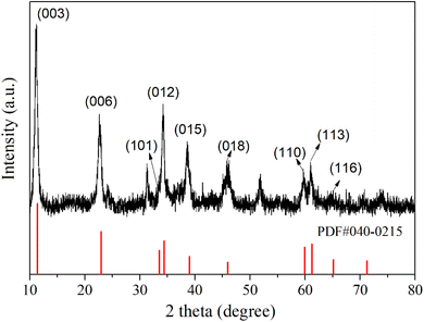
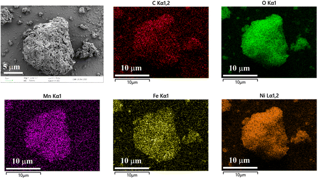
The phase structure of the synthesized LDH was examined using X-ray diffraction (XRD) technology. As depicted in Fig. 1, diffraction peaks are observed at 11.22°, 22.64°, 33.38°, 34.22°, 38.60°, 45.87°, 59.66°, 61.11°, and 64.88° in the XRD pattern of the product. These peaks correspond to the (003), (006), (101), (012), (015), (018), (110), (113), and (116) crystal planes of Ni0.75Fe0.25(CO3)0.125(OH)2·0.38H2O (PDF-040-0215), respectively.37,38 This indicates that the synthesized product possesses a structure analogous to that of Ni0.75Fe0.25(CO3)0.125(OH)2·0.38H2O. The microstructural analysis of the synthesized LDH was conducted using Scanning Electron Microscope (SEM) and Energy Dispersion Spectrum (EDS) to elucidate the morphology and element distribution. In Fig. 2, the LDH particles exhibit a diameter of approximately 10 microns, which are constituted by numerous flake-like subunits measuring around 1 micron in size. In the Zn–Mn deposition-type battery system, the basal plane formed by stacking LDH (Layered Double Hydroxides) flake-like structures offers favourable ionic diffusion pathways and deposition sites for the reversible deposition of Zn and Mn ions. To further probe the elemental composition of the LDH, Energy Dispersion Spectrum (EDS) was employed. The EDS spectrum, as shown in Fig. 2, confirms the presence of carbon (C), manganese (Mn), iron (Fe), nickel (Ni), and oxygen (O) within the LDH structure. Concurrently, the distribution of the five elements above exhibits a strong correlation, indicating that the synthesized LDH are of the (Ni, Mn) Fe-LDH composition, with carbonate anions intercalated within the layers of the LDH structure.The surface chemical composition and electronic states of the synthesized LDH were investigated using X-ray photoelectron spectroscopy. The XPS high-resolution spectrum of Mn 2p, Fe 2p, Ni 2p, C 1s, and O 1s regions are depicted in Fig. 3. The Ni 2p high-resolution XPS spectrum (Fig. 3(a)) exhibits peaks from 850 to 880 eV, with the Ni 2p3/2 main peak at 855.48 eV and a satellite peak at 861.48 eV, both characteristic of Ni(II).38–40 The Ni 2p1/2 peak at 873.18 eV and the observed spin–orbit splitting confirm the presence of divalent nickel in the sample. The Fe 2p XPS high-resolution spectrum (Fig. 3(b)) shows a main Fe 2p3/2 peak at 712.55 eV, alongside a Fe 2p1/2 peak at 725.48 eV, both characteristic of Fe(III).38,41–43 The absence of a satellite peak suggests a minimal presence of Fe(II), indicating that the sample primarily comprises trivalent iron, which is essential for its physicochemical properties. The XPS peaks of Mn 2p3/2 (Fig. 3(c)) can be deconvoluted into three distinct peaks at 638.38 eV, 643.38 eV, and 648.75 eV, corresponding to Mn(II), Mn(III), and Mn(IV), respectively, with Mn(III) being the predominant species.34,41,44 In the C 1s XPS high-resolution spectrum (Fig. 3(d)), three peaks are observed at 284.48 eV, 286.18 eV, and 288.46 eV, corresponding to C–C, C–O–H, and C![[double bond, length as m-dash]](https://www.rsc.org/images/entities/char_e001.gif) O (carbonate group) respectively,45–47 which indicates that the intercalated anions in the synthesized LDH are primarily carbonates, consistent with the scanning electron microscopy-energy dispersion spectrum analysis (SEM-EDS) findings. The O 1s high-resolution XPS spectrum (Fig. 3(e)) features four peaks at binding energy of 529 to 533 eV, which can be attributed to M–O–M (M = Ni, Fe, Mn), M–O–H, O–H, and O–C within the hydroxide layers of the LDH.39,41 The faint peak observed at a binding energy of 192.28 eV in the Cl 2p high-resolution XPS spectrum (Fig. 3(f)) suggests the presence of a minor amount of Cl− within the layered structure of the LDH.48 However, due to the low concentration of Cl−, it remains undetected in the EDS analysis.
O (carbonate group) respectively,45–47 which indicates that the intercalated anions in the synthesized LDH are primarily carbonates, consistent with the scanning electron microscopy-energy dispersion spectrum analysis (SEM-EDS) findings. The O 1s high-resolution XPS spectrum (Fig. 3(e)) features four peaks at binding energy of 529 to 533 eV, which can be attributed to M–O–M (M = Ni, Fe, Mn), M–O–H, O–H, and O–C within the hydroxide layers of the LDH.39,41 The faint peak observed at a binding energy of 192.28 eV in the Cl 2p high-resolution XPS spectrum (Fig. 3(f)) suggests the presence of a minor amount of Cl− within the layered structure of the LDH.48 However, due to the low concentration of Cl−, it remains undetected in the EDS analysis.
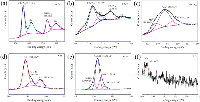 | ||
| Fig. 3 XPS spectrum of the layered double hydroxides. (a) Ni 2p (b) Fe 2p (c) Mn 2p (d) C 1s (e) O 1s (f) Cl 2p. | ||
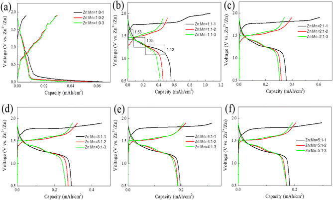
In the following, we utilize synthetically prepared layered double hydroxides (LDH) as the cathode substrate for a Zn–Mn reversible deposition battery, with zinc sheets serving as the anode and an electrolyte composed of a mixture of zinc sulfate and manganese sulfate in varying proportions. Button cells are assembled, and their charge–discharge performance is tested, as depicted in Fig. 4.
As depicted in Fig. 4(a), with a Zn to Mn molar ratio of 1![[thin space (1/6-em)]](https://www.rsc.org/images/entities/char_2009.gif) :
:![[thin space (1/6-em)]](https://www.rsc.org/images/entities/char_2009.gif) 0 in the electrolyte, the areal capacity of the battery reaches 0.04 mA h cm−2, suggesting that a Zn–Mn reversible deposition battery cannot be formed in the absence of Mn in the electrolyte, and the minimal capacity may originate from the slight intercalation of Zn into the LDH.14,41 In Fig. 4(b), when the molar ratio of Zn to Mn in the electrolyte is 1
0 in the electrolyte, the areal capacity of the battery reaches 0.04 mA h cm−2, suggesting that a Zn–Mn reversible deposition battery cannot be formed in the absence of Mn in the electrolyte, and the minimal capacity may originate from the slight intercalation of Zn into the LDH.14,41 In Fig. 4(b), when the molar ratio of Zn to Mn in the electrolyte is 1![[thin space (1/6-em)]](https://www.rsc.org/images/entities/char_2009.gif) :
:![[thin space (1/6-em)]](https://www.rsc.org/images/entities/char_2009.gif) 1, the first discharge areal capacity of the battery reaches 0.56 mA h cm−2. Given the ionic radii of Zn2+ (0.074 nm) and Mn2+ (0.085 nm) and the minimal capacity observed in Fig. 3(a), it is apparent that the battery's capacity is predominantly attributed to the reversible deposition of Zn and Mn, rather than their reversible intercalation/deintercalation. Additionally, three distinct discharge platforms are observable on the discharge curve, at 1.53 V, 1.35 V, and 1.12 V, corresponding to the stepwise reduction of Mn4+ to Mn2+ during the dissolution process, with the charging process being the reverse deposition.33,34,49
1, the first discharge areal capacity of the battery reaches 0.56 mA h cm−2. Given the ionic radii of Zn2+ (0.074 nm) and Mn2+ (0.085 nm) and the minimal capacity observed in Fig. 3(a), it is apparent that the battery's capacity is predominantly attributed to the reversible deposition of Zn and Mn, rather than their reversible intercalation/deintercalation. Additionally, three distinct discharge platforms are observable on the discharge curve, at 1.53 V, 1.35 V, and 1.12 V, corresponding to the stepwise reduction of Mn4+ to Mn2+ during the dissolution process, with the charging process being the reverse deposition.33,34,49
Comparing the first discharge areal capacities of the batteries from Fig. 4(b)–(f) reveals that as the Zn/Mn molar ratio in the electrolyte increases, the areal capacity of the battery continually decreases. When the Zn/Mn molar ratio is 5![[thin space (1/6-em)]](https://www.rsc.org/images/entities/char_2009.gif) :
:![[thin space (1/6-em)]](https://www.rsc.org/images/entities/char_2009.gif) 1, the first discharge areal capacity of the battery is only 0.18 mA h cm−2. An interesting phenomenon is also observed: although the first discharge areal capacity reaches 0.56 mA h cm−2 when the Zn/Mn molar ratio is 1
1, the first discharge areal capacity of the battery is only 0.18 mA h cm−2. An interesting phenomenon is also observed: although the first discharge areal capacity reaches 0.56 mA h cm−2 when the Zn/Mn molar ratio is 1![[thin space (1/6-em)]](https://www.rsc.org/images/entities/char_2009.gif) :
:![[thin space (1/6-em)]](https://www.rsc.org/images/entities/char_2009.gif) 1, the discharge areal capacity drops to 0.41 mA h cm−2 by the third cycle. Conversely, a Zn/Mn molar ratio of 4
1, the discharge areal capacity drops to 0.41 mA h cm−2 by the third cycle. Conversely, a Zn/Mn molar ratio of 4![[thin space (1/6-em)]](https://www.rsc.org/images/entities/char_2009.gif) :
:![[thin space (1/6-em)]](https://www.rsc.org/images/entities/char_2009.gif) 1 in the battery can strike a balance between areal capacity and stability. Further comparisons of the rate and cycling performance of the batteries under different Zn/Mn molar ratio electrolytes will be conducted better to observe the relationship between areal capacity and stability.
1 in the battery can strike a balance between areal capacity and stability. Further comparisons of the rate and cycling performance of the batteries under different Zn/Mn molar ratio electrolytes will be conducted better to observe the relationship between areal capacity and stability.
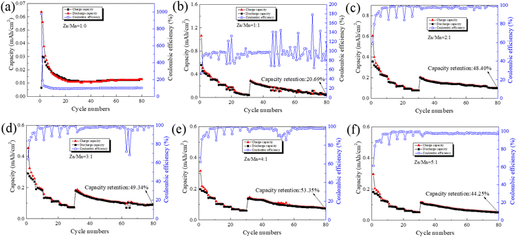
In the subsequent experiments, we utilized synthetically prepared layered double hydroxides (LDH) as the cathode substrate for a Zn–Mn reversible deposition battery, with an area of 1.54 cm2 and an LDH loading of 2 mg. Zinc sheets were employed as the anode, with an area of 2.00 cm2 and a thickness of 0.4 mm. The electrolyte was a mixture of varying proportions of zinc sulfate and manganese sulfate. Button cells were assembled, and their rate performance and cycling stability were tested. For the rate tests, the currents were set at 0.2 mA, 0.4 mA, 0.6 mA, 0.8 mA, 1.0 mA, and 1.2 mA, with each condition subjected to 5 cycles. The cycling tests were conducted at a current of 0.2 mA over 50 cycles, as illustrated in Fig. 5.
In Fig. 5(a), the battery exhibits an initial discharge areal capacity of 0.04 mA h cm−2 at a Zn/Mn molar ratio of 1![[thin space (1/6-em)]](https://www.rsc.org/images/entities/char_2009.gif) :
:![[thin space (1/6-em)]](https://www.rsc.org/images/entities/char_2009.gif) 0 in the electrolyte, with a charge–discharge current of 0.2 mA. The areal capacity approaches 0.01 mA h cm−2 during rate and cycling tests. In Fig. 5(b), at an electrolyte Zn/Mn molar ratio of 1
0 in the electrolyte, with a charge–discharge current of 0.2 mA. The areal capacity approaches 0.01 mA h cm−2 during rate and cycling tests. In Fig. 5(b), at an electrolyte Zn/Mn molar ratio of 1![[thin space (1/6-em)]](https://www.rsc.org/images/entities/char_2009.gif) :
:![[thin space (1/6-em)]](https://www.rsc.org/images/entities/char_2009.gif) 1 and a charge–discharge current of 0.2 mA, the battery's initial discharge areal capacity peaks at 0.56 mA h cm−2. With an increase in the charge–discharge current to 1.2 mA, the discharge areal capacity progressively declines to 0.05 mA h cm−2. Upon reducing the charge–discharge current back to 0.2 mA, the battery's discharge areal capacity partially recovers to 0.30 mA h cm−2, reflecting an area capacity retention rate of 53.35%. After 50 cycles at this current, the discharge areal capacity further diminishes to 0.06 mA h cm−2, with a cumulative capacity retention rate of 20.69%. The battery's coulombic efficiency exhibits notable fluctuations, suggesting that at a 1
1 and a charge–discharge current of 0.2 mA, the battery's initial discharge areal capacity peaks at 0.56 mA h cm−2. With an increase in the charge–discharge current to 1.2 mA, the discharge areal capacity progressively declines to 0.05 mA h cm−2. Upon reducing the charge–discharge current back to 0.2 mA, the battery's discharge areal capacity partially recovers to 0.30 mA h cm−2, reflecting an area capacity retention rate of 53.35%. After 50 cycles at this current, the discharge areal capacity further diminishes to 0.06 mA h cm−2, with a cumulative capacity retention rate of 20.69%. The battery's coulombic efficiency exhibits notable fluctuations, suggesting that at a 1![[thin space (1/6-em)]](https://www.rsc.org/images/entities/char_2009.gif) :
:![[thin space (1/6-em)]](https://www.rsc.org/images/entities/char_2009.gif) 1 Zn/Mn molar ratio in the electrolyte, the initial area capacity of the Zn–Mn reversible deposition battery is relatively high, yet the reversibility is inadequate for sustainable long-term cycling.33,50
1 Zn/Mn molar ratio in the electrolyte, the initial area capacity of the Zn–Mn reversible deposition battery is relatively high, yet the reversibility is inadequate for sustainable long-term cycling.33,50
Similar trends were observed in both rate and cycling tests of batteries with other Zn/Mn molar ratio electrolytes. It was also found that when the electrolyte's Zn/Mn molar ratio is 4![[thin space (1/6-em)]](https://www.rsc.org/images/entities/char_2009.gif) :
:![[thin space (1/6-em)]](https://www.rsc.org/images/entities/char_2009.gif) 1, the initial discharge areal capacity of the battery can reach 0.20 mA h cm−2 in Fig. 5(e). After 30 cycles of rate testing and 50 cycles of cycling testing, the areal capacity retention rate of the battery was 53.35%, which is higher than that of batteries assembled with electrolytes of other Zn/Mn ratios. Therefore, for Zn–Mn reversible deposition batteries constructed with LDH as the cathode substrate, the Zn to Mn molar ratio in the electrolyte has a significant impact on the battery's reversibility, and a Zn/Mn molar ratio of 4
1, the initial discharge areal capacity of the battery can reach 0.20 mA h cm−2 in Fig. 5(e). After 30 cycles of rate testing and 50 cycles of cycling testing, the areal capacity retention rate of the battery was 53.35%, which is higher than that of batteries assembled with electrolytes of other Zn/Mn ratios. Therefore, for Zn–Mn reversible deposition batteries constructed with LDH as the cathode substrate, the Zn to Mn molar ratio in the electrolyte has a significant impact on the battery's reversibility, and a Zn/Mn molar ratio of 4![[thin space (1/6-em)]](https://www.rsc.org/images/entities/char_2009.gif) :
:![[thin space (1/6-em)]](https://www.rsc.org/images/entities/char_2009.gif) 1 may be an appropriate electrolyte formulation.
1 may be an appropriate electrolyte formulation.
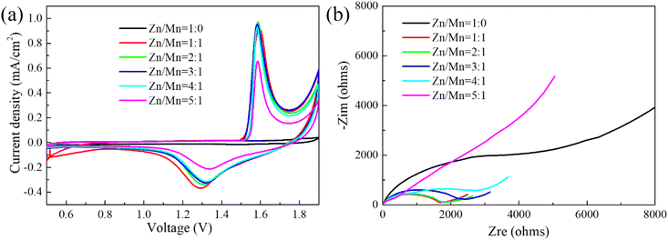
To elucidate the electrochemical reaction mechanisms in Zn–Mn reversible deposition batteries, CV and EIS were utilized to evaluate button cells with a spectrum of Zn/Mn electrolyte ratios, with findings detailed in Fig. 6.
Fig. 6(a) shows the absence of redox peaks within the voltage range of 0.5 to 1.9 V when the electrolyte's Zn/Mn molar ratio is 1![[thin space (1/6-em)]](https://www.rsc.org/images/entities/char_2009.gif) :
:![[thin space (1/6-em)]](https://www.rsc.org/images/entities/char_2009.gif) 0, suggesting that a Zn–Mn reversible deposition battery cannot form without Mn ions,34 corroborating the charge–discharge outcomes in Fig. 4(a). As the Zn/Mn molar ratio in the electrolyte increases from 1
0, suggesting that a Zn–Mn reversible deposition battery cannot form without Mn ions,34 corroborating the charge–discharge outcomes in Fig. 4(a). As the Zn/Mn molar ratio in the electrolyte increases from 1![[thin space (1/6-em)]](https://www.rsc.org/images/entities/char_2009.gif) :
:![[thin space (1/6-em)]](https://www.rsc.org/images/entities/char_2009.gif) 1 to 5
1 to 5![[thin space (1/6-em)]](https://www.rsc.org/images/entities/char_2009.gif) :
:![[thin space (1/6-em)]](https://www.rsc.org/images/entities/char_2009.gif) 1, distinct oxidation and reduction peaks emerge near 1.6 V and 1.3 V, respectively, in the cyclic voltammetry curves, indicating the successful construction of the Zn–Mn reversible deposition battery. Simultaneously, as the electrolyte's Zn/Mn molar ratio rises, the oxidation peak potential shifts to lower voltages while the reduction peak potential elevates, leading to a reduction in the peak potential difference. This trend suggests that a higher Zn/Mn molar ratio enhances the reversibility of the battery,50 potentially due to the multi-element composition of the electrolyte and the facilitative effect of the LDH substrate, which will be further elucidated in the subsequent mechanistic discussion.
1, distinct oxidation and reduction peaks emerge near 1.6 V and 1.3 V, respectively, in the cyclic voltammetry curves, indicating the successful construction of the Zn–Mn reversible deposition battery. Simultaneously, as the electrolyte's Zn/Mn molar ratio rises, the oxidation peak potential shifts to lower voltages while the reduction peak potential elevates, leading to a reduction in the peak potential difference. This trend suggests that a higher Zn/Mn molar ratio enhances the reversibility of the battery,50 potentially due to the multi-element composition of the electrolyte and the facilitative effect of the LDH substrate, which will be further elucidated in the subsequent mechanistic discussion.
Based on the EIS data presented in Fig. 6(b), an equivalent circuit model for the electrode reaction was constructed and fitted to determine the solution resistance (Rs) and charge transfer resistance (Rct), as detailed in Table 1.
| Zn to Mn molar ratios in the electrolyte | Rs/ohms | Rct/ohms |
|---|---|---|
1![[thin space (1/6-em)]](https://www.rsc.org/images/entities/char_2009.gif) : :![[thin space (1/6-em)]](https://www.rsc.org/images/entities/char_2009.gif) 0 0 |
5.27 | 4651 |
1![[thin space (1/6-em)]](https://www.rsc.org/images/entities/char_2009.gif) : :![[thin space (1/6-em)]](https://www.rsc.org/images/entities/char_2009.gif) 1 1 |
9.36 | 1428 |
2![[thin space (1/6-em)]](https://www.rsc.org/images/entities/char_2009.gif) : :![[thin space (1/6-em)]](https://www.rsc.org/images/entities/char_2009.gif) 1 1 |
9.94 | 1493 |
3![[thin space (1/6-em)]](https://www.rsc.org/images/entities/char_2009.gif) : :![[thin space (1/6-em)]](https://www.rsc.org/images/entities/char_2009.gif) 1 1 |
6.49 | 1798 |
4![[thin space (1/6-em)]](https://www.rsc.org/images/entities/char_2009.gif) : :![[thin space (1/6-em)]](https://www.rsc.org/images/entities/char_2009.gif) 1 1 |
4.82 | 2895 |
5![[thin space (1/6-em)]](https://www.rsc.org/images/entities/char_2009.gif) : :![[thin space (1/6-em)]](https://www.rsc.org/images/entities/char_2009.gif) 1 1 |
2.27 | 618 |
Analysis of Table 1 reveals that at a Zn/Mn molar ratio of 1![[thin space (1/6-em)]](https://www.rsc.org/images/entities/char_2009.gif) :
:![[thin space (1/6-em)]](https://www.rsc.org/images/entities/char_2009.gif) 0 in the electrolyte, the battery exhibited an Rs of 5.27 Ω and an Rct of 4651 Ω. There was an absence of Mn redox reactions on the LDH surface, with charge transfer at the interface being significantly impeded, which is consistent with the findings depicted in Fig. 6(a). Upon increasing the Zn/Mn molar ratio to 1
0 in the electrolyte, the battery exhibited an Rs of 5.27 Ω and an Rct of 4651 Ω. There was an absence of Mn redox reactions on the LDH surface, with charge transfer at the interface being significantly impeded, which is consistent with the findings depicted in Fig. 6(a). Upon increasing the Zn/Mn molar ratio to 1![[thin space (1/6-em)]](https://www.rsc.org/images/entities/char_2009.gif) :
:![[thin space (1/6-em)]](https://www.rsc.org/images/entities/char_2009.gif) 1, the Rs decreased to 9.36 Ω and the Rct to 1428 Ω, indicating a marked reduction in the charge transfer impedance and the onset of Mn redox reactions at the electrode surface, corroborating the redox peaks observed in Fig. 6(a). With an increment in the Zn content within the electrolyte, the Rs and Rct of the battery exhibited a trend of initial increase followed by a decrease. This behaviour is primarily attributed to the formation of zinc-containing compounds with inferior conductivity when the Zn/Mn molar ratio ranges from 1
1, the Rs decreased to 9.36 Ω and the Rct to 1428 Ω, indicating a marked reduction in the charge transfer impedance and the onset of Mn redox reactions at the electrode surface, corroborating the redox peaks observed in Fig. 6(a). With an increment in the Zn content within the electrolyte, the Rs and Rct of the battery exhibited a trend of initial increase followed by a decrease. This behaviour is primarily attributed to the formation of zinc-containing compounds with inferior conductivity when the Zn/Mn molar ratio ranges from 1![[thin space (1/6-em)]](https://www.rsc.org/images/entities/char_2009.gif) :
:![[thin space (1/6-em)]](https://www.rsc.org/images/entities/char_2009.gif) 1 to 4
1 to 4![[thin space (1/6-em)]](https://www.rsc.org/images/entities/char_2009.gif) :
:![[thin space (1/6-em)]](https://www.rsc.org/images/entities/char_2009.gif) 1, leading to an elevation in both Rs and Rct.49 The reversible deposition of Mn on the LDH surface was obstructed, a finding supported by subsequent ex situ XRD and SEM-EDS analyses of the battery. At a Zn/Mn molar ratio of 5
1, leading to an elevation in both Rs and Rct.49 The reversible deposition of Mn on the LDH surface was obstructed, a finding supported by subsequent ex situ XRD and SEM-EDS analyses of the battery. At a Zn/Mn molar ratio of 5![[thin space (1/6-em)]](https://www.rsc.org/images/entities/char_2009.gif) :
:![[thin space (1/6-em)]](https://www.rsc.org/images/entities/char_2009.gif) 1 in the electrolyte, a reduction in both Rs and Rct was observed, likely due to the formation of zinc and manganese compounds with enhanced conductivity.51 However, the competitive deposition of excess Zn directly diminished the redox activity of Mn on the LDH surface, an effect that is visually reflected in the lower capacity of mA h cm−2, as illustrated in Fig. 4(f).
1 in the electrolyte, a reduction in both Rs and Rct was observed, likely due to the formation of zinc and manganese compounds with enhanced conductivity.51 However, the competitive deposition of excess Zn directly diminished the redox activity of Mn on the LDH surface, an effect that is visually reflected in the lower capacity of mA h cm−2, as illustrated in Fig. 4(f).
Fig. 7 presents the X-ray diffraction (XRD) analysis results of the cathode in the battery with a Zn/Mn molar ratio of 4![[thin space (1/6-em)]](https://www.rsc.org/images/entities/char_2009.gif) :
:![[thin space (1/6-em)]](https://www.rsc.org/images/entities/char_2009.gif) 1 in the electrolyte under various states, including open-circuit, charged to 1.9 V, discharged to 0.5 V, and recharged to 1.9 V. In the open-circuit state, the cathode contains NiFeMn–CO3 type (PDF No. 40-0125), NiFeMn–SO4 type (PDF No. 36-0382) layered double hydroxides (LDH),52 as well as compounds containing Zn and Mn, which indicates that the experimentally synthesized NiFeMn–CO3 type LDH, serving as the substrate for the Zn–Mn reversible deposition battery, can absorb ions such as SO42−, Zn2+, and Mn2+ from the electrolyte,53,54 forming NiFeMn–SO4 type LDH and compounds containing Zn and Mn (PDF No. 11-0280 and PDF No. 18-0788). The compounds containing Zn and Mn may exhibit a flaky structure, which will be verified through subsequent microscopic morphology observation. When the battery is charged to 1.9 V, the NiFeMn–CO3 type LDH in the cathode disappears, while the NiFeMn–SO4 type LDH persist, and the diffraction peaks of the compounds containing Zn and Mn become more intense and broader. Upon discharging to 0.5 V, the phase composition of the cathode is like that when charged to 1.9 V. When the battery is recharged to 1.9 V, the phase composition of the cathode is comparable to that after discharging to 0.5 V. These results suggest that in the constructed Zn–Mn reversible deposition battery system, the NiFeMn–CO3 type LDH as the substrate absorbs SO42−, Zn2+, and Mn2+ ions from the electrolyte to form more stable NiFeMn–SO4 type LDH and compounds containing Zn and Mn. These substances collectively form the substrate and stably exist throughout the subsequent charge–discharge processes, with Zn and Mn ions undergoing reversible deposition in an amorphous structure on the new composite substrate.
1 in the electrolyte under various states, including open-circuit, charged to 1.9 V, discharged to 0.5 V, and recharged to 1.9 V. In the open-circuit state, the cathode contains NiFeMn–CO3 type (PDF No. 40-0125), NiFeMn–SO4 type (PDF No. 36-0382) layered double hydroxides (LDH),52 as well as compounds containing Zn and Mn, which indicates that the experimentally synthesized NiFeMn–CO3 type LDH, serving as the substrate for the Zn–Mn reversible deposition battery, can absorb ions such as SO42−, Zn2+, and Mn2+ from the electrolyte,53,54 forming NiFeMn–SO4 type LDH and compounds containing Zn and Mn (PDF No. 11-0280 and PDF No. 18-0788). The compounds containing Zn and Mn may exhibit a flaky structure, which will be verified through subsequent microscopic morphology observation. When the battery is charged to 1.9 V, the NiFeMn–CO3 type LDH in the cathode disappears, while the NiFeMn–SO4 type LDH persist, and the diffraction peaks of the compounds containing Zn and Mn become more intense and broader. Upon discharging to 0.5 V, the phase composition of the cathode is like that when charged to 1.9 V. When the battery is recharged to 1.9 V, the phase composition of the cathode is comparable to that after discharging to 0.5 V. These results suggest that in the constructed Zn–Mn reversible deposition battery system, the NiFeMn–CO3 type LDH as the substrate absorbs SO42−, Zn2+, and Mn2+ ions from the electrolyte to form more stable NiFeMn–SO4 type LDH and compounds containing Zn and Mn. These substances collectively form the substrate and stably exist throughout the subsequent charge–discharge processes, with Zn and Mn ions undergoing reversible deposition in an amorphous structure on the new composite substrate.
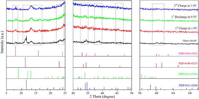 | ||
Fig. 7 Ex situ X-ray diffraction (XRD) analysis of Zn–Mn batteries with an LDHs substrate and a Zn/Mn molar ratio of 4![[thin space (1/6-em)]](https://www.rsc.org/images/entities/char_2009.gif) : :![[thin space (1/6-em)]](https://www.rsc.org/images/entities/char_2009.gif) 1 in the electrolyte under different charge–discharge states. 1 in the electrolyte under different charge–discharge states. | ||
To elucidate the reaction mechanisms of Zn–Mn reversible deposition batteries, SEM-EDS analysis was applied to the cathode with a Zn/Mn molar ratio of 4![[thin space (1/6-em)]](https://www.rsc.org/images/entities/char_2009.gif) :
:![[thin space (1/6-em)]](https://www.rsc.org/images/entities/char_2009.gif) 1 in the electrolyte under different operational states, including open-circuit, charged to 1.9 V, discharged to 0.5 V, and recharged to 1.9 V, as depicted in Fig. 8. At the open-circuit state, a flaky structure was observed on the cathode, and EDS elemental analysis revealed the presence of Zn, Mn, S, and O, suggesting the possible formation of zinc and manganese alkaline sulfates.33,49 Upon charging to 1.9 V, new spherical structures emerged on the cathode. Comparing the EDS elemental analysis before and after charging, a significant increase in Zn and Mn content was observed, indicating that the deposition of Zn and Mn on the cathode surface during charging is the primary source of the battery's charging capacity.14,34 Additionally, a noticeable decrease in Ni and Fe content was detected, suggesting that the dissolution of Ni and Fe accompanies the transformation from NiFeMn–CO3 type LDH to NiFeMn–SO4 type LDH.
1 in the electrolyte under different operational states, including open-circuit, charged to 1.9 V, discharged to 0.5 V, and recharged to 1.9 V, as depicted in Fig. 8. At the open-circuit state, a flaky structure was observed on the cathode, and EDS elemental analysis revealed the presence of Zn, Mn, S, and O, suggesting the possible formation of zinc and manganese alkaline sulfates.33,49 Upon charging to 1.9 V, new spherical structures emerged on the cathode. Comparing the EDS elemental analysis before and after charging, a significant increase in Zn and Mn content was observed, indicating that the deposition of Zn and Mn on the cathode surface during charging is the primary source of the battery's charging capacity.14,34 Additionally, a noticeable decrease in Ni and Fe content was detected, suggesting that the dissolution of Ni and Fe accompanies the transformation from NiFeMn–CO3 type LDH to NiFeMn–SO4 type LDH.
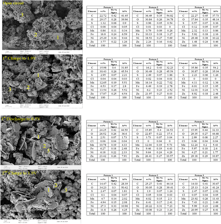 | ||
Fig. 8 Ex situ SEM morphology and elemental analysis of Zn–Mn batteries with an LDHs substrate and a Zn/Mn molar ratio of 4![[thin space (1/6-em)]](https://www.rsc.org/images/entities/char_2009.gif) : :![[thin space (1/6-em)]](https://www.rsc.org/images/entities/char_2009.gif) 1 in the electrolyte under different charge–discharge states. 1 in the electrolyte under different charge–discharge states. | ||
When the battery was discharged to 0.5 V, several spherical structures remained on the cathode, indicating that the newly formed composite substrate was relatively stable. Moreover, a pronounced flaky structure appeared, with corresponding EDS elemental analysis showing a significant increase in S and Zn, suggesting an increase in zinc alkaline sulfates.33 However, a specific decrease in Mn content indicated that the manganese alkaline sulfates formed during the charging process undergo dissolution reactions. The extent of deposition and dissolution is evidently not equivalent, which may cause the battery's capacity to fade.14,55 Upon recharging to 1.9 V, the prominent flaky structure still existed, but with noticeable irregularities at the edges, indicating that the dissolution of zinc alkaline sulfates occurs, and the released Zn ions participate in the redeposition reactions with Mn ions. Compared to the state after discharging to 0.5 V, the spherical structures were more abundant upon recharging to 1.9 V, and the Mn content increased again, indicating that the deposition reactions of Zn and Mn are primarily concentrated on the spherical structures, which are the previously mentioned composite substrates.
In summary, using NiFeMn–CO3 type LDH as the cathode substrate in Zn–Mn reversible deposition batteries, a composite substrate containing NiFeMn–SO4 type LDH and compounds of Zn and Mn is formed on the cathode during the open-circuit and initial charging processes. In the subsequent charge–discharge processes, reversible deposition reactions of Zn and Mn occur on the composite substrate, primarily involving the deposition and dissolution of amorphous zinc and manganese alkaline sulfates; the rates of deposition and dissolution reactions for compounds containing Zn and Mn are not consistent.
Further insight into the reaction mechanisms of Zn–Mn reversible deposition batteries is garnered through the analysis of elemental property changes on the cathode surface at a Zn/Mn molar ratio of 4![[thin space (1/6-em)]](https://www.rsc.org/images/entities/char_2009.gif) :
:![[thin space (1/6-em)]](https://www.rsc.org/images/entities/char_2009.gif) 1 in the electrolyte during states of open-circuit, charging to 1.9 V, discharging to 0.5 V, and recharging to 1.9 V, as illustrated in Fig. 8.
1 in the electrolyte during states of open-circuit, charging to 1.9 V, discharging to 0.5 V, and recharging to 1.9 V, as illustrated in Fig. 8.
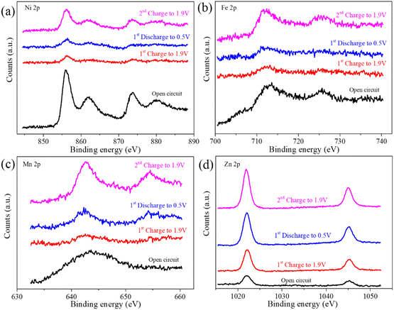
Fig. 9(a) and (b) demonstrate that the binding energies of Ni 2p3/2, Ni 2p1/2, Fe 2p3/2, and Fe 2p1/2 peaks remain relatively stable throughout the battery's charge–discharge cycle. Nonetheless, a significant reduction in the corresponding peak intensities is observed during the initial charge–discharge phase. Upon recharging to 1.9 V, partial recovery of peak intensities is observed, suggesting a dissolution and reformation process from NiFeMn–CO3 to NiFeMn–SO4 type LDH during the initial charge–discharge cycle, which results in the formation of a novel composite substrate. This finding is consistent with the SEM-EDS analysis presented in Fig. 7. Fig. 9(c) shows that in the open-circuit state, Mn primarily exists in the divalent form within the cathode. During the initial charge–discharge cycle followed by recharging, Mn undergoes deposition and dissolution reactions. The deposition process mainly involves the oxidation of divalent Mn to tetravalent Mn, while the dissolution reaction represents the reduction of Mn. Additionally, the broadened peaks at the binding energies of 654.4 eV for Mn 2p1/2 and 642.6 eV for Mn 2p3/2 indicate the formation of compounds containing divalent, trivalent, and tetravalent Mn during the oxidation process.34,41 Fig. 9(d) confirms the presence of Zn in the cathode during the open-circuit state, consistent with prior SEM-EDS analysis. Zn's continued presence throughout the initial charge–discharge and subsequent recharging cycles indicates its active role in the Mn deposition and dissolution processes on the cathode. The use of a selectively permeable separator is proposed to regulate Zn's influence on cathode reactions.
Finally, integrating the results from the charge–discharge performance, cycling stability, and electrochemical impedance spectroscopy of the battery, along with the ex situ XRD, SEM-EDS, and XPS analyses of the cathode, we propose a schematic illustration of the Zn/Mn reversible deposition battery with NiFeMn-LDH as the cathode substrate, as shown in Fig. 10. When the Zn/Mn molar ratio in the mixed electrolyte is 4![[thin space (1/6-em)]](https://www.rsc.org/images/entities/char_2009.gif) :
:![[thin space (1/6-em)]](https://www.rsc.org/images/entities/char_2009.gif) 1, the NiFeMn-LDH as the cathode substrate can induce Zn2+, Mn2+, and SO42− ions from the electrolyte to undergo reversible dissolution–deposition reactions on its surface in the form of an amorphous mixture. At this ratio, the battery's capacity and cycling stability are well-balanced. This work provides significant insights for the construction of MnO2-free Zn/Mn reversible deposition batteries.
1, the NiFeMn-LDH as the cathode substrate can induce Zn2+, Mn2+, and SO42− ions from the electrolyte to undergo reversible dissolution–deposition reactions on its surface in the form of an amorphous mixture. At this ratio, the battery's capacity and cycling stability are well-balanced. This work provides significant insights for the construction of MnO2-free Zn/Mn reversible deposition batteries.
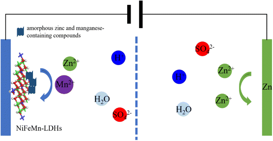 | ||
| Fig. 10 The schematic illustration of the mechanism for the Zn–Mn reversible deposition battery based on LDHs. | ||
3 Conclusions
In this research, we developed a reversible dissolution–precipitation aqueous battery using NiFeMn-LDH as the cathode material substrate. Through comprehensive electrochemical and microstructural characterization, we explored the battery's performance and the underlying reaction mechanisms. Results indicate that at a Zn/Mn molar ratio of 4![[thin space (1/6-em)]](https://www.rsc.org/images/entities/char_2009.gif) :
:![[thin space (1/6-em)]](https://www.rsc.org/images/entities/char_2009.gif) 1 in the electrolyte, the battery maintains a balance between capacity and stability, achieving an area capacity of 0.2 mA h cm−2. The battery's capacity is primarily attributed to the reversible dissolution–precipitation of amorphous zinc and manganese-containing compounds, enabled by the NiFeMn-LDH substrate, which offers numerous active sites for this process. Future work will focus on electrolyte optimization to enhance the reversibility of these reactions and improve the battery's cyclic stability.
1 in the electrolyte, the battery maintains a balance between capacity and stability, achieving an area capacity of 0.2 mA h cm−2. The battery's capacity is primarily attributed to the reversible dissolution–precipitation of amorphous zinc and manganese-containing compounds, enabled by the NiFeMn-LDH substrate, which offers numerous active sites for this process. Future work will focus on electrolyte optimization to enhance the reversibility of these reactions and improve the battery's cyclic stability.
Data availability
The data supporting the findings of this study are available within the article.Author contributions
The manuscript was written through the contributions of all authors. All authors have approved the final version of the manuscript.Conflicts of interest
There are no conflicts to declare.Acknowledgements
The authors express their sincere gratitude for the financial support provided by The Science and Technology Plan Project of Guizhou Province [No. Qian Ke He Jichu-[2024]QingNian 016], The Scientific Research and Cultivation Project of Liupanshui Normal University (LPSSY2023KJYBPY08, LPSSY2023KJYBPY03), The Science and Technology Development Project of Liupanshui (52020-2023-0-2-7, 52020-2023-0-2-12), Liupanshui Normal University High-Level Talents Research Initiation Special Project [LPSSYKYJJ202404], Carbon Neutral Engineering Research Center of Guizhou Colleges and Universities in Coal Industry (Qian Jiao Ji[2023]No.044).Notes and references
- J. Li, Y. Wang, Y. Wang, Y. Guo, S. Zhang, H. Song, X. Li, Q. Gao, W. Shang, S. Hu, H. Zheng and X. Li, Nano Mater. Sci., 2023, 5, 237–245 CrossRef CAS.
- Y. Zhang, A. Chen and J. Sun, J. Energy Chem., 2020, 54, 655–667 CrossRef.
- H. Zhang, Z. Shen, D. Jia, W. Zhou, X. Wang, J. Liu and X. He, J. Alloys Compd., 2024, 991, 174413 CrossRef CAS.
- Y. Zhang, S. Luo, G. Yang, L. Yu, S. Ye, C. Jiang and Y. Wu, Mater. Lett., 2024, 361, 135993 CrossRef CAS.
- Y. Ren, H. Li, Y. Rao, H. Zhou and S. Guo, Energy Environ. Sci., 2024, 17, 425–441 RSC.
- X. Li, Z. Xu, Y. Qian and Z. Hou, Energy Storage Mater., 2022, 53, 72–78 CrossRef.
- N. Zhang, Y.-R. Ji, J.-C. Wang, P.-F. Wang, Y.-R. Zhu and T.-F. Yi, J. Energy Chem., 2023, 82, 423–463 CrossRef CAS.
- Y. Wu, B. Yan, Y. Liu, J. Kong, X. Lin, M. Gong, L. Zhang and D. Wang, J. Power Sources, 2024, 602, 234313 CrossRef CAS.
- H. Yao, W. Dong, X. Ji and S. Cheng, Surf. Interfaces, 2024, 44, 103669 CrossRef CAS.
- T.-H. Wu, S.-L. Cheng and S.-C. Liao, Electrochim. Acta, 2024, 490, 144290 CrossRef CAS.
- S. Cui, D. Zhang and Y. Gan, J. Power Sources, 2023, 579, 233293 CrossRef CAS.
- H. Li, H. Yao, X. Sun, C. Sheng, W. Zhao, J. Wu, S. Chu, Z. Liu, S. Guo and H. Zhou, Chem. Eng. J., 2022, 446, 137205 CrossRef CAS.
- Y. Zhao, X. Xia, Q. Li, Y. Wang, Y. Fan, Y. Zhao, W. Liu and X. Sun, Energy Storage Mater., 2024, 67, 103268 CrossRef.
- Z. Zhong, J. Li, L. Li, X. Xi, Z. Luo, G. Fang, S. Liang and X. Wang, Energy Storage Mater., 2022, 46, 165–174 CrossRef.
- W. Liu, X. Zhang, Y. Huang, B. Jiang, Z. Chang, C. Xu and F. Kang, J. Energy Chem., 2021, 56, 365–373 CrossRef CAS.
- H. Wang, T. Wang, G. Stevenson, M. Chamoun and R. W. Lindström, Energy Storage Mater., 2023, 63, 103008 CrossRef.
- C. Xie, T. Li, C. Deng, Y. Song, H. Zhang and X. Li, Energy Environ. Sci., 2020, 13, 135–143 RSC.
- M. Zhang, H. Hua, P. Dai, Z. He, L. Han, P. Tang, J. Yang, P. Lin, Y. Zhang, D. Zhan, J. Chen, Y. Qiao, C. C. Li, J. Zhao and Y. Yang, Adv. Mater., 2023, 35, 2208630 CrossRef CAS PubMed.
- D. Wu, L. Housel, S. J. Kim, N. Sadique, C. Quilty, L. Wu, R. Tappero, S. Nicholas, S. Ehrlish, Y. Zhu, A. Marschilok, E. Takeuchi, D. Bock and K. Takeuchi, Energy Environ. Sci., 2020, 13, 4322–4333 RSC.
- Z. Liu, H.-B. He, Z.-X. Luo, X.-F. Wang and J. Zeng, Trans. Nonferrous Met. Soc. China, 2023, 33, 1193–1204 CrossRef CAS.
- X. Xie, H. Fu, Y. Fang, B. Lu, J. Zhou and S. Liang, Adv. Energy Mater., 2022, 12, 2102393 CrossRef CAS.
- H. Chen, C. Dai, F. Xiao, Q. Yang, S. Cai, M. Xu, H. Fan and S.-J. Bao, Adv. Mater., 2022, 34, 2109092 CrossRef CAS PubMed.
- K. Ma, Q. Li, C. Hong, G. Yang and C. Wang, ACS Appl. Mater. Interfaces, 2021, 13, 55208–55217 CrossRef CAS PubMed.
- X. Xue, Z. Liu, S. Eisenberg, Q. Ren, D. Lin, E. Coester, H. Zhang, J. Z. Zhang, X. Wang and Y. Li, ACS Energy Lett., 2023, 8, 4658–4665 CrossRef CAS.
- Z. Yang, X. Pan, Y. Shen, R. Chen, T. Li, L. Xu and L. Mai, Small, 2022, 18, 2107743 CrossRef CAS PubMed.
- V. R. Kankanallu, X. Zheng, D. Leschev, N. Zmich, C. Clark, C.-H. Lin, H. Zhong, S. Ghose, A. M. Kiss, D. Nykypanchuk, E. Stavitski, E. S. Takeuchi, A. C. Marschilok, K. J. Takeuchi, J. Bai, M. Ge and Y.-C. K. Chen-Wiegart, Energy Environ. Sci., 2023, 16, 2464–2482 RSC.
- D. Wu, S. T. King, N. Sadique, L. Ma, S. N. Ehrlich, S. Ghose, J. Bai, H. Zhong, S. Yan, D. C. Bock, E. S. Takeuchi, A. C. Marschilok, L. M. Housel, L. Wang and K. J. Takeuchi, J. Mater. Chem. A, 2023, 11, 16279–16292 RSC.
- Z. R. Mansley, Y. Zhu, D. Wu, E. S. Takeuchi, A. C. Marschilok, L. Wang and K. J. Takeuchi, Nano Lett., 2023, 23, 8657–8663 CrossRef CAS PubMed.
- D. Wu, L. M. Housel, S. T. King, Z. R. Mansley, N. Sadique, Y. Zhu, L. Ma, S. N. Ehrlich, H. Zhong, E. S. Takeuchi, A. C. Marschilok, D. C. Bock, L. Wang and K. J. Takeuchi, J. Am. Chem. Soc., 2022, 144, 23405–23420 CrossRef CAS PubMed.
- P. Ruan, X. Xu, D. Zheng, X. Chen, X. Yin, S. Liang, X. Wu, W. Shi, X. Cao and J. Zhou, ChemSusChem, 2022, 15, e202201118 CrossRef CAS PubMed.
- C. Tamtong, W. Kao-ian, P. Kidkhunthod and S. Kheawhom, Integr. Ferroelectr., 2023, 238, 216–223 CrossRef CAS.
- C. Yan, X. Tong, Y. Qu, Y. Zhou, N. Pang, S. Xu, D. Xiong, L. Wang and P. K. Chu, Vacuum, 2021, 191, 110353 CrossRef CAS.
- X. Shen, X. Wang, Y. Zhou, Y. Shi, L. Zhao, H. Jin, J. Di and Q. Li, Adv. Funct. Mater., 2021, 31, 2101579 CrossRef CAS.
- H. Moon, K.-H. Ha, Y. Park, J. Lee, M.-S. Kwon, J. Lim, M.-H. Lee, D.-H. Kim, J. H. Choi, J.-H. Choi and K. T. Lee, Adv. Sci., 2021, 8, 2003714 CrossRef CAS PubMed.
- D. Qiu, H. Wang, T. Ma, J. Huang, Z. Meng, D. Fan, C. R. Bowen, H. Lu, Y. Liu and S. Chandrasekaran, ACS Nano, 2024, 18, 21651–21684 CrossRef CAS PubMed.
- F. Ran, M. Hu, S. Deng, K. Wang, W. Sun, H. Peng and J. Liu, RSC Adv., 2024, 14, 11482–11512 RSC.
- Y. Zhao, P. Zhang, J. Liang, X. Xia, L. Ren, L. Song, W. Liu and X. Sun, Adv. Mater., 2022, 34, 2204320 CrossRef CAS PubMed.
- Q. Ding, J. Li, S. Li, J. Wang, W. Huang, S. Sun, Y. Xu and H. Li, J. Energy Storage, 2023, 67, 107556 CrossRef.
- J. Meng, Y. Song, Z. Qin, Z. Wang, X. Mu, J. Wang and X.-X. Liu, Adv. Funct. Mater., 2022, 32, 2204026 CrossRef CAS.
- M. Rastgoo-Deylami and A. Esfandiar, ACS Appl. Energy Mater., 2021, 4, 2377–2387 CrossRef CAS.
- Y. Zhao, P. Zhang, J. Liang, X. Xia, L. Ren, L. Song, W. Liu and X. Sun, Adv. Mater., 2022, 34, 2204320 CrossRef CAS PubMed.
- X. Xuan, M. Qian, L. Pan, T. Lu, Y. Gao, L. Han, L. Wan, Y. Niu and S. Gong, J. Energy Chem., 2022, 70, 593–603 CrossRef CAS.
- S. Chandrasekaran, R. Hu, L. Yao, L. Sui, Y. Liu, A. Abdelkader, Y. Li, X. Ren and L. Deng, Nano-Micro Lett., 2023, 15, 48 CrossRef CAS PubMed.
- C. Wang, C. Zhou, B. Zhang, X. Ou, L. Cao, C. Peng and J. Zhang, RSC Adv., 2019, 9, 9075–9078 RSC.
- L. Chai, A. Bala Musa, J. Pan, J. Song, Y. Sun and X. Liu, J. Power Sources, 2022, 544, 231887 CrossRef CAS.
- H.-M. Kim, B.-C. Cha and D.-W. Kim, RSC Adv., 2023, 13, 26918–26924 RSC.
- C. Xu, L. Zhang, F. Liu, R. Zhang and H. Yue, RSC Adv., 2024, 14, 12454–12462 RSC.
- Z. Wu, Y. Wu, Q. Yuan, J. Zhang, Y. Dou and J. Han, ACS Appl. Mater. Interfaces, 2023, 15, 38540–38549 CrossRef CAS PubMed.
- X. Guo, J. Zhou, C. Bai, X. Li, G. Fang and S. Liang, Mater. Today Energy, 2020, 16, 100396 CrossRef.
- X. Yang, Z. Jia, W. Wu, H.-Y. Shi, Z. Lin, C. Li, X.-X. Liu and X. Sun, Chem. Commun., 2022, 58, 4845–4848 RSC.
- X. Yang, Z. Jia, W. Wu, H.-Y. Shi, Z. Lin, C. Li, X.-X. Liu and X. Sun, Chem. Commun., 2022, 58, 4845–4848 RSC.
- H. Yi, S. Liu, C. Lai, G. Zeng, M. Li, X. Liu, B. Li, X. Huo, L. Qin, L. Li, M. Zhang, Y. Fu, Z. An and L. Chen, Adv. Energy Mater., 2021, 11, 2002863 CrossRef CAS.
- Y. Wang, Q. Pan, Y. Qiao, X. Wang, D. Deng, F. Zheng, B. Chen and J. Qiu, Adv. Mater., 2023, 35, 2210871 CrossRef CAS PubMed.
- L. Zhang, T. Zhang, Y. Zhao, G. Dong, S. Lv, S. Ma, S. Song and M. Quintana, Nano Res., 2023, 17, 1646–1654 CrossRef.
- L. Wei and Z. Gao, RSC Adv., 2023, 13, 8427–8463 RSC.
| This journal is © The Royal Society of Chemistry 2024 |

