 Open Access Article
Design of an LiF-rich interface layer using high-concentration fluoroethylene carbonate and lithium bis(fluorosulfonyl)imide (LiFSI) to stabilize Li metal batteries
Huan Li *a and
Yanxiao Lib
aNIO Co., Ltd, Shanghai, 200000, China. E-mail: lihuan@stu.ouc.edu.cn
bHangzhou POWCLIN Medical Technology Co., Ltd, Hangzhou, 311305, China
First published on 20th November 2024
Abstract
The development of high-energy-density Li metal batteries is limited by the uncontrollable growth of Li dendrites and an unstable Li/electrolyte interface during long-term Li plating/stripping. In this work, using high-concentration fluoroethylene carbonate (FEC) electrolyte, an LiF-rich interface layer was generated on the Li metal surface. This LiF-rich interface layer could effectively inactivate the high reactivity of the Li metal surface and suppress lithium dendrite growth, forming a uniform and dense structure at the Li/electrolyte interface to stabilize Li metal batteries. Owing to the enhanced interface stability offered by the high-concentration FEC electrolyte with LiFSI additive, the Li‖LiFePO4 cell presented high capacity retention (89.1%) after 200 cycles at 1C (165 mA g−1) and retained over 133.7 mA h g−1 at 10C rate, whereas only 115.0 mA h g−1 was achieved in the traditional carbonate ester electrolyte. The results show an obvious improvement in the cycle performance and rate capability of Li metal batteries containing a high-concentration FEC electrolyte with LiFSI as an additive.
1. Introduction
Lithium (Li) metal, which has a high theoretical specific capacity (3860 mA h g−1) and a low electrochemical potential (−3.04 V vs. standard hydrogen electrode),1 is deemed a promising anode material for high-energy-density lithium ion batteries.2However, uncontrolled lithium dendrite growth during long-term plating/stripping leads to a low coulombic efficiency and serious safety issues, making metallic lithium anodes unsuitable for practical application. An optimal strategy to improve the electrochemical performance of Li metal batteries is employing an LiF-rich interface layer.3,4
Herein, we report a facile strategy to fabricate a uniform and dense LiF-rich interface layer on the highly electrochemically reactive Li metal surface, which avoids the use of special additives and complex interfacial modifications.5–7 Lithium bis(fluorosulfonyl)imide (LiFSI) and fluoroethylene carbonate (FEC) were used as the lithium salt and solvent, respectively, which significantly improved the fast-charging capability and cycling stability of Li metal batteries. LiF is a good electronic insulator and can block electron tunnelling through the SEI, which has been deemed the main factor contributing to sustained electrolyte decomposition and lithium dendrite growth; therefore, an LiF-rich interface layer can effectively stabilize the electrodeposition of lithium ions.8,9 FEC can lead to the generation of LiF-rich solid-electrolyte interface (SEI) on the surface of Li metals, effectively alleviating lithium dendrite growth and capacity fading and improving the coulombic efficiency (CE) and cycling performance significantly. Meanwhile, the lowest unoccupied molecular orbital (LUMO) energy of LiFSI (−1.70 eV) is lower than those of FEC (−0.87 eV), EMC (−0.1 eV) and DEC (0 eV), indicating its higher tendency to react with Li metal than the solvent molecules under standard conditions.8,10,11 The reduction of FSI anions on the Li metal surface would produce more fluorine-rich species in the interface layer.4,12,13 In this paper, we designed a LiF-rich interface layer using high-concentration FEC combined with lithium bis(fluorosulfonyl)imide (LiFSI) to stabilize Li metal batteries and minimize the electrodeposition of lithium ions, which improved the electrochemical performance of the Li‖LiFePO4 cell significantly. Especially, in this review, the proposed structure and composition of SEIs are focused upon and the role of LiF and Li2CO3 in SEI is further analyzed.
2. Experimental details
2.1 Electrode preparation
To prepare the electrode, 94 wt% LFP (lithium iron phosphate) powder (Jiangsu Lenengy Battery Joint-stock Co., Ltd), 2.5 wt% polyvinylidene fluoride (PVDF) (Arkema (Changshu) Fluorochemical Co., Ltd) and 3.5 wt% carbon black (Super P; Imerys) were mixed uniformly. Then, the prepared slurry was coated onto aluminum foil; the coating weight was 13 mg cm−2 and the compaction density was 2.2 g cm−3. Electrochemical measurements were conducted by assembling coin-type cells in an argon-filled glove box. Li metal foil (China Energy Lithium Co., Ltd) was employed as the reference and counter electrodes. The cycled coin cells were disassembled in an argon-filled glove box, and the electrodes were cleaned in dimethyl carbonate (DMC) before FTIR, XPS, XRD and SEM tests.2.2 Physical characterization
Sample morphology and elemental composition were analyzed by scanning electron microscopy (SEM, Zeiss Gemini Sigma 500) and EDS, respectively. FTIR spectra were recorded using a Thermo Scientific, Nicolet iS5, iD7 ATR instrument. XPS was performed on a Thermo Scientific K-alpha X-ray photoelectron spectrometer using monochromatic Al Kα radiation. The binding energies were referenced to the C 1s peak at 284.80 eV. The sample crystal structure was studied using X-ray diffraction (XRD 7000, Shimadzu) with Cu Kα radiation (λ = 1.5406 nm). In order to protect the electrodes from air exposure during the XRD test, the cycled Li metal anodes and LFP cathodes were covered with a tape.2.3 Electrochemical studies
The electrochemical impedance spectral (EIS) measurements of the coin cells were performed on a VersaSTAT MC (AMETEK, Princeton Applied Research) analyzer at 3.4 V, and the EIS results were fitted using Z-view software with an appropriate equivalent circuit. Long-term cycling and rate capability testing were performed using battery testers from Neware Battery Test System (Neware Technology Ltd, China). Cycling was normally done between 2.0 and 3.8 V at a rate of 1C (165 mA g−1).3. Results and discussion
3.1 Electrochemical characterization
FEC and LiFSI are known to have a significant impact on the Li-metal anode/electrolyte interface. To evaluate the influence of high-concentration FEC combined with LiFSI on the electrochemical performance of the Li-metal anode, Li‖LiFePO4 cells were assembled using 1 M LiFSI/FEC–EMC–DEC (FEC![[thin space (1/6-em)]](https://www.rsc.org/images/entities/char_2009.gif) :
:![[thin space (1/6-em)]](https://www.rsc.org/images/entities/char_2009.gif) EMC
EMC![[thin space (1/6-em)]](https://www.rsc.org/images/entities/char_2009.gif) :
:![[thin space (1/6-em)]](https://www.rsc.org/images/entities/char_2009.gif) DEC = 6
DEC = 6![[thin space (1/6-em)]](https://www.rsc.org/images/entities/char_2009.gif) :
:![[thin space (1/6-em)]](https://www.rsc.org/images/entities/char_2009.gif) 2
2![[thin space (1/6-em)]](https://www.rsc.org/images/entities/char_2009.gif) :
:![[thin space (1/6-em)]](https://www.rsc.org/images/entities/char_2009.gif) 2, by weight) and 1 M LiPF6/EC–EMC–DEC (EC
2, by weight) and 1 M LiPF6/EC–EMC–DEC (EC![[thin space (1/6-em)]](https://www.rsc.org/images/entities/char_2009.gif) :
:![[thin space (1/6-em)]](https://www.rsc.org/images/entities/char_2009.gif) EMC
EMC![[thin space (1/6-em)]](https://www.rsc.org/images/entities/char_2009.gif) :
:![[thin space (1/6-em)]](https://www.rsc.org/images/entities/char_2009.gif) DEC = 6
DEC = 6![[thin space (1/6-em)]](https://www.rsc.org/images/entities/char_2009.gif) :
:![[thin space (1/6-em)]](https://www.rsc.org/images/entities/char_2009.gif) 2
2![[thin space (1/6-em)]](https://www.rsc.org/images/entities/char_2009.gif) :
:![[thin space (1/6-em)]](https://www.rsc.org/images/entities/char_2009.gif) 2, by weight) as electrolytes, respectively, and their cycling stability and rate capability at high current densities were compared.
2, by weight) as electrolytes, respectively, and their cycling stability and rate capability at high current densities were compared.
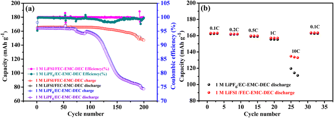
The cycling stability of Li‖LiFePO4 cells with 1 M LiFSI/FEC–EMC–DEC and 1 M LiPF6/EC–EMC–DEC as electrolytes were compared, as shown in Fig. 1a. Notably, the Li metal anode in LiFSI/FEC–EMC–DEC showed dramatically higher cycling stability (89.1%) than that of the Li metal anode in LiPF6/EC–EMC–DEC (47.0%) after 200 cycles at 1C (165 mA g−1). Fig. 1b shows the comparison of the rate capability of Li‖LiFePO4 cells with 1 M LiFSI/FEC–EMC–DEC and 1 M LiPF6/EC–EMC–DEC as electrolytes at different current densities. At 0.1C, the Li‖LiFePO4 cells with 1 M LiFSI/FEC–EMC–DEC and 1 M LiPF6/EC–EMC–DEC as electrolytes delivered discharge capacities of 163.2 and 162.5 mA h g−1, respectively. At 10C, the Li‖LiFePO4 cells with 1 M LiFSI/FEC–EMC–DEC electrolyte maintained a high discharge capacity of 133.7 mA h g−1 (81.9% of the capacity at 0.1C), whereas the capacity of the Li‖LiFePO4 cells with 1 M LiPF6/EC–EMC–DEC electrolyte was limited to only 115.0 mA h g−1 (70.8% of the capacity at 0.1C). The superior capacity retention of the Li‖LiFePO4 cells with 1 M LiFSI/FEC–EMC–DEC electrolyte to those with 1 M LiPF6/EC–EMC–DEC electrolyte at higher current densities illustrates that high-concentration FEC with the LiFSI additive effectively improves the cycling stability and rate capability of the Li‖LiFePO4 cells.
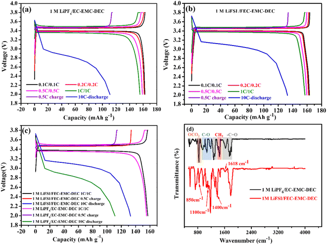
Fig. 2a–c show the comparison of the charge/discharge curves of Li‖LiFePO4 cells with 1 M LiPF6/EC–EMC–DEC and 1 M LiFSI/FEC–EMC–DEC as electrolytes at different current densities in the range of 2.0 and 3.8 V. Clearly, the high-concentration FEC electrolyte with the LiFSI additive generated lower overpotentials than conventional carbonate-based electrolytes. The F-rich interface layer was further analyzed by FTIR, as shown in Fig. 2d. The absorption peaks located at 1180 and 1300 cm−1 indicate the symmetric and asymmetric stretching of the C–F bonds in F-rich material.14 The peaks at 1670 cm−1 and 1700 cm−1 denote C![[double bond, length as m-dash]](https://www.rsc.org/images/entities/char_e001.gif) C stretching and C
C stretching and C![[double bond, length as m-dash]](https://www.rsc.org/images/entities/char_e001.gif) O stretching, respectively. The characteristic absorption peak of LiF was observed at a wavelength of 1618 cm−1.14,15 This means that the LiF-rich material was produced in the high-concentration FEC electrolyte with LiFSI as the additive. In addition, the characteristic peaks of Li2CO3 at 850, 1100 and 1400 cm−1 were clearly found in the Li-metal anodes obtained from the 1 M LiFSI/FEC–EMC–DEC electrolyte, demonstrating the presence of Li2CO3.16 However, the absorbance peaks of the Li-metal anodes obtained from 1 M LiPF6/EC–EMC–DEC were located at 950–1190 cm−1 and 1646–1765 cm−1, corresponding to C–O and C
O stretching, respectively. The characteristic absorption peak of LiF was observed at a wavelength of 1618 cm−1.14,15 This means that the LiF-rich material was produced in the high-concentration FEC electrolyte with LiFSI as the additive. In addition, the characteristic peaks of Li2CO3 at 850, 1100 and 1400 cm−1 were clearly found in the Li-metal anodes obtained from the 1 M LiFSI/FEC–EMC–DEC electrolyte, demonstrating the presence of Li2CO3.16 However, the absorbance peaks of the Li-metal anodes obtained from 1 M LiPF6/EC–EMC–DEC were located at 950–1190 cm−1 and 1646–1765 cm−1, corresponding to C–O and C![[double bond, length as m-dash]](https://www.rsc.org/images/entities/char_e001.gif) O stretching in organic products, which originate from the decomposition of organic solvents.17,18
O stretching in organic products, which originate from the decomposition of organic solvents.17,18
3.2 Li metal anode surface characterization
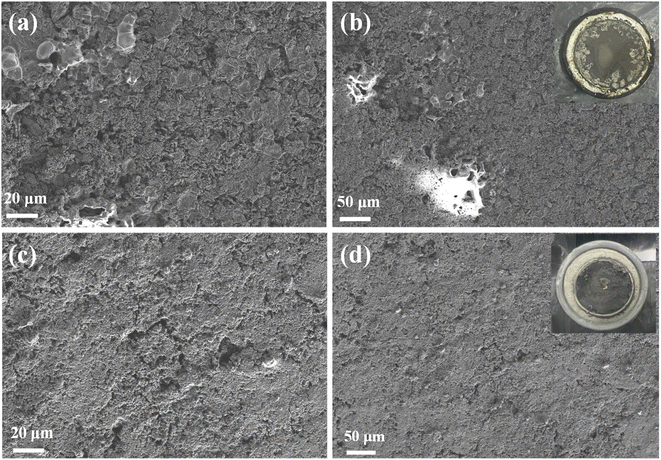
After 200 cycles, the Li metal surface in LiPF6/EC–EMC–DEC showed substantial cracking and a loose substructure (Fig. 3a and b). This morphology is caused by the continuous reaction between Li metal and the electrolyte, as evidenced by the poor cycling stability and low coulombic efficiency. In sharp contrast, in high-concentration FEC electrolytes with the LiFSI additive, the Li metal maintained a dense and uniform surface (Fig. 3c and d).LiF plays an important role in the formation of a stabilized and uniform interface layer to suppress Li dendrite growth. LiF is a robust electrical insulator to prevent electrons from crossing the interface layer. Moderate mechanical strength of the SEI film is also crucial for its performance. It has been proposed that a higher proportion of inorganic components, such as LiF and Li2CO3, would enhance the mechanical performance of the SEI film.19 Moreover, due to its low diffusing energy and high surface energy for Li ions,8,9 LiF exhibits extremely high capability in enhancing the surface diffusion of lithium ions during Li plating/stripping and inducing a uniform and dendrite-free morphology. The addition of FEC into liquid electrolytes not only changes the composition of the SEI but also the structure of the SEI. The ionic conductivity of the SEI is not only determined by the ionic conductivity of each single component but also by the way in which these species are assembled together, that is, the structure of the SEI. Although some studies have reported that LiF is an ionic insulator (from 10−13 to 10−14 S cm−1), Li ions can still diffuse through the grain boundary of LiF in the SEI. Therefore, we can speculate that even if LiF does not conduct Li ions, they can still travel through the LiF/LiF grain boundary.19,20
The dense Li metal surface morphology generated by the high-concentration FEC electrolyte and LiFSI additive was quantitatively confirmed by mapping the fluorine distribution (Fig. 4 and 5). Li metal cycled in LiFSI/FEC–EMC–DEC exhibited a much higher fluorine content (16.7 at%) than that cycled in LiPF6/EC–EMC–DEC (6.5 at%), indicating that a fluoride-rich interface layer was formed on the surface of the Li metal in the presence of high-concentration FEC and LiFSI additive. The dense and uniform surface could minimize the side reactions between deposited Li and the electrolyte, resulting in a much higher Li deposition/stripping coulombic efficiency (as shown in Fig. 1a).
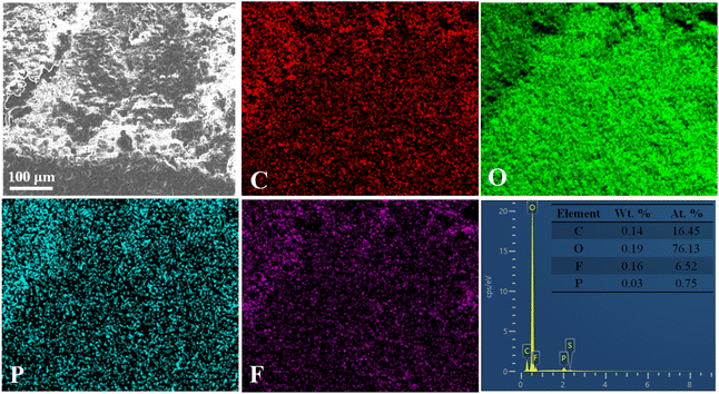 | ||
| Fig. 4 The corresponding elemental mapping images for carbon, oxygen, phosphorus, fluorine and EDS spectrum of the Li foils obtained after 200 cycles in 1 M LiPF6/EC–EMC–DEC. | ||
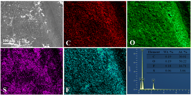 | ||
| Fig. 5 The corresponding elemental mapping images for carbon, oxygen, sulfur, and fluorine and EDS spectrum of the Li foils obtained after 200 cycles in 1 M LiFSI/FEC–EMC–DEC. | ||
The Nyquist plots of the Li‖LiFePO4 cells with 1 M LiPF6/EC–EMC–DEC and 1 M LiFSI/FEC–EMC–DEC as electrolytes are shown in Fig. 6a. The inset shows the equivalent circuit constructed to fit the EIS, in which Rs represents ohmic resistance, C1 and R2 represent the capacitance and resistance of the passivation interface layer, respectively, C2 and R3 represent the double-layer capacitance and charge transfer resistance, respectively, while W represents Warburg impedance.21,22 The charge transfer resistance (Rct) of the Li‖LiFePO4 cells with the 1 M LiFSI/FEC–EMC–DEC electrolyte was slightly lower than that of the Li‖LiFePO4 cells with the 1 M LiPF6/EC–EMC–DEC electrolyte, which is in accordance with the charge/discharge results. In general, the impedance spectrum of a cell is analyzed and fitted to an electric circuit model to extract the parameters related to the single electrochemical processes occurring inside the cell. However, given the complexity in separating these processes from the EIS spectra, the distribution of relaxation time (DRT) is often used to deconvolute the impedance curves in the time domain and distinguish the polarization effects that are normally overlapped in the frequency domain.23–25 Depending on the value of the time constant, a specific peak can be attributed to a defined physical process. The main processes that can be identified are the transport of lithium ions through the SEI (10−5 < τ < 10−2 s) and electrode charge transfer (10−2 < τ < 10 s).23 The peak areas in DRT represent the impedance values of specific electrochemical process; according to the DRT results, the diffusion rate of Li ions in the SEI generated by the LiFSI/FEC–EMC–DEC electrolyte is generally faster than that in the 1 M LiPF6/EC–EMC–DEC electrolyte (Fig. 6).
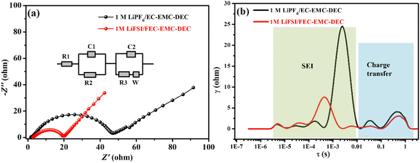 | ||
| Fig. 6 (a) Nyquist plots and (b) DRT profiles of the Li‖LiFePO4 cells with 1 M LiPF6/EC–EMC–DEC and 1 M LiFSI/FEC–EMC–DEC as electrolytes. | ||
The cycled Li metal anodes and LFP cathodes were analyzed by XRD, as shown in Fig. 7. In order to protect the electrodes from air exposure during the XRD test, the cycled Li metal anodes and LFP cathodes were covered with a tape. There was a slight diffraction peak from the tape, but it did not interfere with the detection of the target substances. In the XRD patterns, the Li metal anode obtained after 200 cycles in the LiFSI/FEC–EMC–DEC electrolyte presented the typical LiF diffraction peaks centered at 2θ = 38.8°, 45.1°, and 65.9°, corresponding to the (111), (200), and (220) planes of the LiF face-centered cubic crystal.3,9,26–29
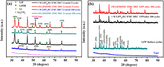 | ||
| Fig. 7 XRD results of (a) Li-metal anodes after 5 and 200 cycles (b) and LiFePO4 electrodes after 200 cycles in 1 M LiPF6/EC–EMC–DEC and 1 M LiFSI/FEC–EMC–DEC. | ||
The diffraction peaks at 32.7°, 36.2°, 49.1°, 51.8°, 56.2°, 62.6° and 76.5° could be indexed to crystalline LiOH,30 indicating that there were numerous LiOH molecules on the surface of Li metal after 5 cycles in LiPF6/EC–EMC–DEC and 1 M LiFSI/FEC–EMC–DEC electrolytes.
Diffraction peaks appeared at around 36.1°, 51.6°, and 64.6° for the Li metal anode cycled 200 cycles in the LiPF6/EC–EMC–DEC electrolyte, which can be attributed to the crystalline metallic Li phase,26,27,31 and LiF diffraction peaks were not found. It can be speculated that metallic Li is deposited on the Li metal/electrolyte interface during Li plating/stripping. In addition, the peaks at 44.6° and 65.6° could be ascribed to Li2CO3.32–34 Fig. 7b shows the LiFePO4 electrodes obtained after 200 cycles in the LiPF6/EC–EMC–DEC and LiFSI/FEC–EMC–DEC electrolytes maintained the LiFePO4 crystal structure, according to the XRD results.35–37
The XRD results indicate that during long-term Li plating/stripping, LiF can be formed on the surface of the Li metal anode in the presence of the high-concentration FEC electrolyte and LiFSI additive. Moreover, LiF can effectively improve the lithium-ion deposition behavior and suppress the growth of lithium dendrites.3
Furthermore, the elemental composition of passivation interface films was determined by XPS, and the results are presented in Fig. 8. As shown in Fig. 8a, the passivation interface film generated on the Li metal anode cycled 200 cycles in LiFSI/FEC–EMC–DEC consisted of Li, C, O, F, N and S components. The fitting C 1s spectrum is shown in Fig. 8b. The peak at 284.5 eV is the characteristic peak of the C–C/C–H bond, and those at 286.0 eV and at 288.6 eV can be typically ascribed to the C–O–C, O–C![[double bond, length as m-dash]](https://www.rsc.org/images/entities/char_e001.gif) O/Li2CO3 bonds.38,39 Furthermore, the characteristic peak at 290 eV corresponds to the C–F bond.40,41
O/Li2CO3 bonds.38,39 Furthermore, the characteristic peak at 290 eV corresponds to the C–F bond.40,41
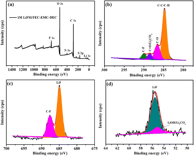 | ||
| Fig. 8 XPS analysis of the SEI layers on the Li-metal anode cycled 200 cycles in 1 M LiFSI/FEC–EMC–DEC. (a) Survey spectrum and (b–d) C 1s, F 1s and Li 1s spectra, respectively. | ||
As shown in Fig. 8c, there were two peaks in the F 1s spectrum belonging to the C–F bonds at 687.6 eV and LiF at 684.8 eV.13 In the Li 1s spectrum (Fig. 8d), the peak of LiF (55.6 eV) was also found. The XPS analysis convincingly confirms the generation of abundant LiF and Li2CO3 on the surface of the Li metal anode in the LiFSI/FEC–EMC–DEC electrolyte during long-term Li plating/stripping.
As shown in Fig. 9, the Li|Li symmetrical cell cycled in 1 M LiPF6/EC–EMC–DEC electrolyte exhibited a sharp voltage drop after 50 h, which is characteristic of an internal short circuit caused by serious dendrite growth. In contrast, after introducing high-concentration FEC and LiFSI additive in the electrolyte, the Li|Li symmetrical cell exhibited a small overpotential and very stable cycling process for more than 75 h, which proves the improved deposition behavior of lithium ions in the presence of the 1 M LiFSI/FEC–EMC–DEC electrolyte.
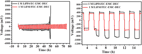 | ||
| Fig. 9 The cycling performance of symmetrical cells with a Li metal anode in 1 M LiFSI/FEC–EMC–DEC and 1 M LiPF6/EC–EMC–DEC electrolytes at 0.5 mA cm−2. | ||
The overpotential remained almost constant over time, suggesting that the SEI on the Li surface in the 1 M LiFSI/FEC–EMC–DEC electrolyte was very stable, while in 1 M LiPF6/EC–EMC–DEC electrolyte, the overpotential was much higher initially and fluctuated considerably after 6 h. The results suggest that the FEC-based electrolyte is beneficial to the formation of an LiF-rich interface, which reduces the ion transport resistance and growth of lithium dendrites effectively during Li plating/stripping.42
4. Conclusions
A high-concentration FEC electrolyte with LiFSI as an additive was used in Li‖LiFePO4 cells to generate a LiF-rich interface layer that effectively protects the Li metal. The Li metal anode in LiFSI/FEC–EMC–DEC (60% FEC by weight) showed greater stability (89.1%) than that in LiPF6/EC–EMC–DEC (47.0%) after 200 cycles at 1C (165 mA g−1). At 10C, the Li‖LiFePO4 cells with 1 M LiFSI/FEC–EMC–DEC electrolyte maintained a high discharge capacity of 133.7 mA h g−1 (81.9% of the capacity at 0.1C), whereas the capacity of Li‖LiFePO4 cells with 1 M LiPF6/EC–EMC–DEC electrolyte was limited to only 115.0 mA h g−1 (70.8% of the capacity at 0.1C).The comparison of FTIR, XRD, SEM, EDS, DRT and XPS results of the cycled Li metal anodes suggests that the uniform and LiF-rich interface layer generated on the surface of the Li metal anode may be the major factor contributing to the improvement in cycle performance and rate capability. Moreover, the findings also highlight that LiF and Li2CO3, the important inorganic components of the SEI film, play a significant role in improving the structural morphology and ionic conductivity of the SEI film. These studies further reveal the possible application of Li metal batteries in lithium-ion storage devices and help us understand the possible mechanisms underlying the performance improvement of Li metal batteries with high-concentration FEC and LiFSI additive. This work also provides guidance to developing new technologies and strategies to achieve long-lasting and superior-rate-capability Li metal batteries.
Data availability
The authors confirm that the data supporting the findings of this study are available within the article. The DRT tools analysis scripts used for computing distribution relaxation times (DRT) from electrochemical impedance spectroscopy (EIS) data in this article can be found at https://github.com/ciuccislab/DRTtools.git with DOI: https://doi.org/10.1016/j.electacta.2015.09.097.Author contributions
H. L. proposed the concept and conceived the mechanism, designed the experiment, carried out the electrochemical work, and analyzed the electrochemical data and wrote the manuscript. YX. L. analyzed the electrochemical data and revised the manuscript.Conflicts of interest
There are no conflicts to declare.References
- S. Sun, S. Myung, G. Kim, D. Lee, H. Son, M. Jang, E. Park, B. Son, Y.-G. Jung and U. Paik, J. Mater. Chem. A, 2020, 8, 17229–17237 RSC.
- J. Ko, D. H. Cho, D.-J. Kim and Y. S. Yoon, J. Alloys Compd., 2020, 845, 156280 CrossRef CAS.
- J. Ko and Y. S. Yoon, Ceram. Int., 2019, 45, 30–49 CrossRef CAS.
- X. Han and J. Sun, Chem. Commun., 2020, 56, 6047–6049 RSC.
- C. N. Hong, M. Yan, O. Borodin, T. P. Pollard, L. Wu, M. Reiter, D. G. Vazquez, K. Trapp, J. M. Yoo and N. Shpigel, Energy Environ. Sci., 2024, 17, 4137–4146 RSC.
- M.-H. Kim, T.-U. Wi, J. Seo, A. Choi, S. Ko, J. Kim, U. Jung, M. S. Kim, C. Park and S. Jin, Nano Lett., 2023, 23, 3582–3591 CrossRef CAS PubMed.
- T. Li, X.-Q. Zhang, P. Shi and Q. Zhang, Joule, 2019, 3, 2647–2661 CrossRef CAS.
- X. Fan, L. Chen, X. Ji, T. Deng, S. Hou, J. Chen, J. Zheng, F. Wang, J. Jiang and K. Xu, Chem, 2018, 4, 174–185 CAS.
- Y. Yuan, F. Wu, G. Chen, Y. Bai and C. Wu, J. Energy Chem., 2019, 37, 197–203 CrossRef.
- L. Fan, K. Lin, J. Wang, R. Ma and B. Lu, Adv. Mater., 2018, 30, 1800804 CrossRef PubMed.
- Z. Xie, X. An, Z. Wu, X. Yue, J. Wang, X. Hao, A. Abudula and G. Guan, J. Mater. Sci. Technol., 2021, 74, 119–127 CrossRef CAS.
- J. Qian, W. A. Henderson, W. Xu, P. Bhattacharya, M. Engelhard, O. Borodin and J.-G. Zhang, Nat. Commun., 2015, 6, 1–9 Search PubMed.
- X. Q. Zhang, X. B. Cheng, X. Chen, C. Yan and Q. Zhang, Adv. Funct. Mater., 2017, 27, 1605989 CrossRef.
- S.-M. Xu, H. Duan, J.-L. Shi, T.-T. Zuo, X.-C. Hu, S.-Y. Lang, M. Yan, J.-Y. Liang, Y.-G. Yang and Q.-H. Kong, Nano Res., 2020, 13, 430–436 CrossRef CAS.
- H. Kim, Y. S. Kim and J. Yoo, Sustainable Energy Fuels, 2020, 4, 3282–3287 RSC.
- N. Tian, C. Hua, Z. Wang and L. Chen, J. Mater. Chem. A, 2015, 3, 14173–14177 RSC.
- P. Verma, P. Maire and P. Novák, Electrochim. Acta, 2010, 55, 6332–6341 CrossRef CAS.
- A. Basile, A. Bhatt and A. O'mullane, Nat. Commun., 2016, 7, ncomms11794 CrossRef CAS PubMed.
- H. Wu, H. Jia, C. Wang, J. G. Zhang and W. Xu, Adv. Energy Mater., 2021, 11, 2003092 CrossRef CAS.
- J. Tan, J. Matz, P. Dong, J. Shen and M. Ye, Adv. Energy Mater., 2021, 11, 2100046 CrossRef CAS.
- H. Li, Q. Li, L. Li, X. Cao and W. Wang, J. Appl. Electrochem., 2021, 51, 753–760 CrossRef CAS.
- H. Li, L. Chen and Z. Chen, SN Appl. Sci., 2020, 2, 1–10 Search PubMed.
- P. Iurilli, C. Brivio and V. Wood, Energy Technol., 2022, 10, 2200547 CrossRef CAS.
- T. H. Wan, M. Saccoccio, C. Chen and F. Ciucci, Electrochim. Acta, 2015, 184, 483–499 CrossRef CAS.
- H. Duan, C. Wang, R. Yu, W. Li, J. Fu, X. Yang, X. Lin, M. Zheng, X. Li and S. Deng, Adv. Energy Mater., 2023, 13, 2300815 CrossRef CAS.
- Y. Yuan, F. Wu, Y. Bai, Y. Li, G. Chen, Z. Wang and C. Wu, Energy Storage Mater., 2019, 16, 411–418 CrossRef.
- D. Lee, S. Sun, J. Kwon, H. Park, M. Jang, E. Park, B. Son, Y. Jung, T. Song and U. Paik, Adv. Mater., 2020, 32, 1905573 CrossRef CAS PubMed.
- J. Liu, J. Li, Z. Luo, Y. Liu, Z. Liu, Z. Chen, Y. Ren, B. Zhu, R. Wang and Q. Zhang, Sol. Energy Mater. Sol. Cells, 2019, 203, 110188 CrossRef CAS.
- F. Zhao, Q. Sun, C. Yu, S. Zhang, K. Adair, S. Wang, Y. Liu, Y. Zhao, J. Liang and C. Wang, ACS Energy Lett., 2020, 5, 1035–1043 CrossRef CAS.
- Z. Li, S. Ganapathy, Y. Xu, J. R. Heringa, Q. Zhu, W. Chen and M. Wagemaker, Chem. Mater., 2017, 29, 1577–1586 CrossRef CAS PubMed.
- H. Chen, Y. Yang, D. T. Boyle, Y. K. Jeong, R. Xu, L. S. de Vasconcelos, Z. Huang, H. Wang, H. Wang and W. Huang, Nat. Energy, 2021, 1–9 Search PubMed.
- Y. Bi, T. Wang, M. Liu, R. Du, W. Yang, Z. Liu, Z. Peng, Y. Liu, D. Wang and X. Sun, RSC Adv., 2016, 6, 19233–19237 RSC.
- C. Peng, F. Liu, Z. Wang, B. P. Wilson and M. Lundström, J. Power Sources, 2019, 415, 179–188 CrossRef CAS.
- S. Zheng, H. Geng, S. N. Eliseeva and B. Wang, Energy Mater., 2022, 2, 200042 CrossRef CAS.
- R. Shahid and S. Murugavel, Mater. Chem. Phys., 2013, 140, 659–664 CrossRef CAS.
- I. Takahashi, T. Mori, T. Yoshinari, Y. Orikasa, Y. Koyama, H. Murayama, K. Fukuda, M. Hatano, H. Arai and Y. Uchimoto, J. Power Sources, 2016, 309, 122–126 CrossRef CAS.
- K. Zaghib, A. Mauger, F. Gendron and C. Julien, Ionics, 2008, 14, 271–278 CrossRef CAS.
- M. Klett, R. Eriksson, J. Groot, P. Svens, K. C. Högström, R. W. Lindström, H. Berg, T. Gustafson, G. Lindbergh and K. Edström, J. Power Sources, 2014, 257, 126–137 CrossRef CAS.
- X. Wang, Z. Feng, J. Huang, W. Deng, X. Li, H. Zhang and Z. Wen, Carbon, 2018, 127, 149–157 CrossRef CAS.
- L. P. Méndez De Leo, E. de la Llave, D. Scherlis and F. J. Williams, J. Chem. Phys., 2013, 138, 114707 CrossRef PubMed.
- J. Hao, F. Yang, S. Zhang, H. He, G. Xia, Y. Liu, C. Didier, T. Liu, W. K. Pang and V. K. Peterson, Proc. Natl. Acad. Sci. U. S. A., 2020, 117, 2815–2823 CrossRef CAS PubMed.
- Z. Wang, Z. Sun, Y. Shi, F. Qi, X. Gao, H. Yang, H. M. Cheng and F. Li, Adv. Energy Mater., 2021, 11, 2100935 CrossRef CAS.
| This journal is © The Royal Society of Chemistry 2024 |

