 Open Access Article
Polysulfide-mediating properties of nickel phosphide carbon composite nanofibers as free-standing interlayers for lithium–sulfur batteries†
Ayaulym Belgibayeva *a,
Gulderaiym Turarovaa,
Akmaral Dangaliyevaa,
Fail Sultanova,
Arailym Nurpeissovaa,
Aliya Mukanova
 *a and
Zhumabay Bakenov
 *abc
*abc
aNational Laboratory Astana, Kabanbay Batyr Ave. 53, Astana 010000, Kazakhstan. E-mail: ayaulym.belgibayeva@nu.edu.kz; aliya.mukanova@nu.edu.kz; zbakenov@nu.edu.kz
bDepartment of Chemical and Materials Engineering, School of Engineering and Digital Sciences, Nazarbayev University, Kabanbay Batyr Ave. 53, Astana 010000, Kazakhstan
cInstitute of Batteries LLC, Kabanbay Batyr Ave. 53, Astana 010000, Kazakhstan
First published on 15th November 2024
Abstract
Issues such as the polysulfide shuttle effect and sulfur loss challenge the development of high-energy-density lithium–sulfur batteries. To address these limitations, a tailored approach is introduced using nickel phosphide carbon composite nanofibers (NixP/C) with controlled surface oxidation layers. These nanofibers feature a hierarchical structure that leverages the benefits of nickel phosphide nanoparticles and a carbonaceous matrix to enable efficient sulfur encapsulation and suppress polysulfide diffusion. Comprehensive characterization and electrochemical testing reveal that NixP/C, when employed as interlayers in a cell with a bio-waste-derived carbon-based sulfur cathode, significantly enhance electrochemical performance by increasing charge–discharge capacities and reducing charge-transfer resistance. Post-mortem analyses further show effective polysulfide trapping and conversion on the cathode side, preventing their shuttle to the anode, which results in a remarkable cycle stability of up to 200 cycles at 2C with a high discharge capacity of about 800 mA h g−1. These findings confirm the potential of NixP/C to improve lithium–sulfur battery technologies and demonstrate their applicability in diverse lithium–sulfur cell configurations.
1. Introduction
Lithium–sulfur batteries have emerged as a promising candidate for next-generation energy storage systems due to their high theoretical energy density, as well as abundance and low cost of sulfur.1–3 However, the commercial viability of lithium–sulfur batteries has been hindered by several challenges, including polysulfide shuttle effects and the poor electrical conductivity of sulfur.4–6 To overcome these limitations, inserting multifunctional free-standing interlayers between the sulfur cathode and separator has shown significant potential.7–9 These interlayers serve as a physical barrier for polysulfides, catalyze their conversion to final products, and provide both electronic and ionic paths to the cathode, boosting the kinetics of electrochemical reactions.10,11On the other hand, the effect of interlayers is typically assessed by comparing them to interlayer-free cells using cathode materials with initially poor electrochemical performance. Although interlayers are considered beneficial for a wide range of sulfur cathodes with different designs, their impact on cells with already optimized cathodes remains underexplored.12 Therefore, further studies are needed to evaluate the effectiveness of interlayers in combination with advanced cathode materials, such as the recently developed bio-waste-derived graphene-like carbon-based sulfur composites (GPC@S).13
Multifunctional free-standing interlayers usually consist of carbon matrix composited with metal-based polar materials.14,15 Among such polar materials, transition metal phosphides attract particular interest due to their catalytic properties towards conversion of polysulfides and high electrical conductivity.16–18 Although there are no significant differences in the dissociation energies of Li2S on the surface of different transition metal phosphides, when incorporated into sulfur cathode, nickel phosphide significantly enhanced the electrochemical performance of the cell compared to iron phosphide and cobalt phosphide.19,20 However, there are only few works utilizing nickel phosphide carbon composites as interlayers for lithium–sulfur batteries.21–23
A study on Ni2P and NiP2 interlayers highlighted the benefits of a Ni-rich phosphide (Ni2P) interlayer, which combines polar and conductive properties to effectively capture and catalyze the conversion of lithium polysulfides.21 The lithium–sulfur cell with a Ni2P@CF interlayer achieved an initial discharge capacity of 930 mA h g−1 at 1C and retained 551 mA h g−1 after 1000 cycles, demonstrating only 0.04% capacity decay per cycle, showcasing the importance of integrating both physical and catalytic functions in the interlayer.
Generally, the improved polysulfide-mediating properties of metal phosphides are believed to be attributed to their natural surface oxidation layer.24 Recently, nickel phosphide carbon composite nanofibers (NixP/C) comprised of Ni2P with traces of Ni12P5 and a tailored surface oxidation layer have been developed by our group and applied as anode material for lithium-ion batteries.25 In this work, polysulfide-mediating properties of developed composite nanofibers and their application as interlayers in lithium–sulfur batteries with GPC@S composite cathode were studied for the first time.
2. Experimental
2.1 Materials
Polyvinylpyrrolidone (PVP, Mw = 1![[thin space (1/6-em)]](https://www.rsc.org/images/entities/char_2009.gif) 300
300![[thin space (1/6-em)]](https://www.rsc.org/images/entities/char_2009.gif) 000) from Sigma-Aldrich was vacuum-dried at 60 °C overnight and stored in an airtight container containing silica gel. Nickel nitrate hexahydrate (Ni(NO3)2·6H2O) and phosphoric acid (H2PO4, 85%) from ThermoFisher Scientific, lithium sulfide (Li2S), sulfur, lithium nitrate (LiNO3), lithium bis(trifluoromethane)sulfonimide (LiTFSI), 1,3-dioxolane (DOL), and 1,2-dimethoxyethane (DME) from Sigma-Aldrich were used as received, without any pre-treatment. A 1 M solution of Li2S6 in DOL/DME (v/v, 1
000) from Sigma-Aldrich was vacuum-dried at 60 °C overnight and stored in an airtight container containing silica gel. Nickel nitrate hexahydrate (Ni(NO3)2·6H2O) and phosphoric acid (H2PO4, 85%) from ThermoFisher Scientific, lithium sulfide (Li2S), sulfur, lithium nitrate (LiNO3), lithium bis(trifluoromethane)sulfonimide (LiTFSI), 1,3-dioxolane (DOL), and 1,2-dimethoxyethane (DME) from Sigma-Aldrich were used as received, without any pre-treatment. A 1 M solution of Li2S6 in DOL/DME (v/v, 1![[thin space (1/6-em)]](https://www.rsc.org/images/entities/char_2009.gif) :
:![[thin space (1/6-em)]](https://www.rsc.org/images/entities/char_2009.gif) 1) was prepared by mixing Li2S and sulfur in a 1
1) was prepared by mixing Li2S and sulfur in a 1![[thin space (1/6-em)]](https://www.rsc.org/images/entities/char_2009.gif) :
:![[thin space (1/6-em)]](https://www.rsc.org/images/entities/char_2009.gif) 5 molar ratio and magnetically stirring the mixture at 60 °C overnight. Part of this concentrated solution was diluted to 0.002 M by DOL/DME (v/v, 1
5 molar ratio and magnetically stirring the mixture at 60 °C overnight. Part of this concentrated solution was diluted to 0.002 M by DOL/DME (v/v, 1![[thin space (1/6-em)]](https://www.rsc.org/images/entities/char_2009.gif) :
:![[thin space (1/6-em)]](https://www.rsc.org/images/entities/char_2009.gif) 1) mixture for polysulfide adsorption test. Rice husk (RH) from the Kyzylorda region of Kazakhstan was thoroughly washed with hot distilled water and vacuum-dried at 110 °C for 5 hours.
1) mixture for polysulfide adsorption test. Rice husk (RH) from the Kyzylorda region of Kazakhstan was thoroughly washed with hot distilled water and vacuum-dried at 110 °C for 5 hours.
2.2 Synthesis of NixP/C fiber mat interlayer
NixP/C fiber mats were synthesized as reported elsewhere.25 The electrospinning precursor solution was prepared by dissolving 0.602 g of PVP in six mL of ethanol. To this, 0.448 g of Ni(NO3)2·6H2O, two mL of distilled water, and 105 μL of H3PO4 were added. The mixture was stirred for 15 hours at room temperature at 600 rpm. Electrospinning was performed at 18 kV with a flow rate of 0.8 mL h−1, a 10 cm tip-to-collector distance, and a flat collector. Humidity inside the electrospinning machine was controlled at 25% (±3%). The fiber mats were dried at 110 °C for 11 hours in air and annealed at 700 °C for one hour in N2 + (4%) H2.2.3 Physical characterizations and lithium polysulfide adsorption and conversion tests
The crystalline phases were analyzed through X-ray diffraction (XRD, Miniflex, Rigaku, with Cu Kα radiation, λ = 1.5406 Å). Raman spectra were recorded using Raman Spectroscopy (LabRAM, Horiba) with a 532 nm excitation wavelength, 1% of the initial power (15 mW), and a 10 seconds accumulation time. Surface chemistry of the fiber mats, both before and after cycling, was examined using X-ray Photoelectron Spectroscopy (XPS NEXSA, Thermo Scientific).The morphology of the fibers was observed by scanning electron microscopy (SEM, Crossbeam500, Zeiss). The microstructure was examined using transmission electron microscopy (TEM, JEM-1400 Plus, JEOL) at 120 kV, as well as FE-TEM and energy-dispersive spectroscopy (EDS, Tecnai F30 S-Twin) at 300 kV. Nitrogen adsorption–desorption analysis was performed on the Micromeritics TriStar II Plus, with the specific surface area determined through the Brunauer–Emmett–Teller (BET) method.
The lithium polysulfide adsorption test was performed by placing 10 mg of prepared fibers into 3 mL of 0.002 M Li2S6 solution in DOL/DME (v/v, 1![[thin space (1/6-em)]](https://www.rsc.org/images/entities/char_2009.gif) :
:![[thin space (1/6-em)]](https://www.rsc.org/images/entities/char_2009.gif) 1). After 30 minutes of adsorption test, the resulting solutions were subjected to UV-vis analysis on the Evolution 300 UV-vis Spectrophotometer.
1). After 30 minutes of adsorption test, the resulting solutions were subjected to UV-vis analysis on the Evolution 300 UV-vis Spectrophotometer.
Lithium polysulfide conversion properties were studied in a symmetric cell with the NixP/C fiber mats used as both working and counter electrodes, separated by a polypropylene film soaked in 50 μL of 1 M Li2S6 in DOL![[thin space (1/6-em)]](https://www.rsc.org/images/entities/char_2009.gif) :
:![[thin space (1/6-em)]](https://www.rsc.org/images/entities/char_2009.gif) DME (v/v = 1/1). Cyclic voltammetry (CV) was performed at a scan rate of 3 mV s−1 within the cell voltage range of −1.5 to 1.5 V.
DME (v/v = 1/1). Cyclic voltammetry (CV) was performed at a scan rate of 3 mV s−1 within the cell voltage range of −1.5 to 1.5 V.
2.4 Synthesis of GPC@S cathode
GPC@S cathodes were prepared following the previously reported procedures.13 First, GPC was obtained from a RH after carbonization at 500 °C under an Ar flow and activation by mixing with potassium hydroxide in a 1![[thin space (1/6-em)]](https://www.rsc.org/images/entities/char_2009.gif) :
:![[thin space (1/6-em)]](https://www.rsc.org/images/entities/char_2009.gif) 4 ratio, heating at 150 °C overnight in air, and then carbonization at 800 °C under an Ar flow for 1.5 hours. After the activation process, the resulting GPC powder was washed multiple times with distilled water until the pH reached approximately 6–7, ensuring the removal of residual alkaline impurities, then dried in a vacuum at 150 °C for 12 hours.
4 ratio, heating at 150 °C overnight in air, and then carbonization at 800 °C under an Ar flow for 1.5 hours. After the activation process, the resulting GPC powder was washed multiple times with distilled water until the pH reached approximately 6–7, ensuring the removal of residual alkaline impurities, then dried in a vacuum at 150 °C for 12 hours.
Next, to prepare GPC@S cathodes, sulfur was immobilized onto the obtained carbon using a simple melt-diffusion method. GPC and sulfur were thoroughly mixed in a 4![[thin space (1/6-em)]](https://www.rsc.org/images/entities/char_2009.gif) :
:![[thin space (1/6-em)]](https://www.rsc.org/images/entities/char_2009.gif) 6 ratio using an agate mortar. The resulting mixture was then transferred to a Teflon-lined autoclave in an argon atmosphere and heated to 160 °C for 16 hours in a muffle oven.
6 ratio using an agate mortar. The resulting mixture was then transferred to a Teflon-lined autoclave in an argon atmosphere and heated to 160 °C for 16 hours in a muffle oven.
2.5 Electrochemical characterizations
The electrochemical characterizations were performed using CR2032 coin-type cells in the glove box filled with Ar gas (99.9995%). Typically, a mixture containing 80 wt% GPC@S, 10 wt% acetylene black, and 10 wt% polyvinylidene fluoride was dispersed in N-methyl-2-pyrrolidone to create a uniform slurry. The slurry was uniformly cast onto carbon-coated aluminum foil, with the layer thickness carefully controlled using a doctor blade. The coated foil was then dried at 60 °C in a vacuum oven for 12 hours. Circular disc electrodes (16 mm in diameter) were precisely cut from the foil, ensuring an areal sulfur loading of approximately 1.7–1.8 mg cm−2.The as-prepared NixP/C fiber mat interlayer was punched into the same size as the cathode and inserted between the cathode and separator, soaked in the 50 μL of electrolyte composed of 1 M LiTFSI in DOL/DME (v/v = 1/1) with 0.1 M LiNO3 as the additive.
Galvanostatic charge–discharge tests of cells with and without NixP/C fiber mat interlayer were performed using Neware battery testers (BTS4000) in a potential range of 1.85–2.8 V vs. Li/Li+ at 0.2C (1C = 1675 mA g−1). The rate performance was measured at different current densities from 0.2 to 3C. CV was conducted in the same potential range at a scan rate of 0.1 mV s−1 and electrochemical impedance spectroscopy (EIS) measurements were performed at an AC amplitude of 5 mV in the frequency range of 100 kHz–0.01 Hz using a Biologic VMP3 potentiostat.
The interlayers from the disassembled cells after the fifth charge and discharge at 0.2C were washed with DOL solvent, dried at 60 °C for 4 hours in a vacuum antechamber attached to the Ar-filled glove box, and stored in a sealed zip bag to prevent oxidation in ambient conditions before being subjected to XPS analysis.
3. Results and discussion
3.1 Physical properties of NixP/C fiber mat
The detailed physical characteristics of the synthesized NixP/C fiber mats were reported elsewhere.25 The XRD results in Fig. 1a confirm the formation of NixP within the composite nanofibers, with characteristic peaks for Ni2P at 40°, 44°, 47°, 54°, and 75°, corresponding to a hexagonal structure (space group P62m). A minor secondary phase, Ni12P5, with a tetragonal structure (space group 87: I4/m), is detected and quantified as minimal via Rietveld refinement (Fig. 1b). This minor presence of Ni12P5 contributes to the electronic conductivity and polysulfide adsorption capacity, enhancing the composite's function as an interlayer in lithium–sulfur batteries.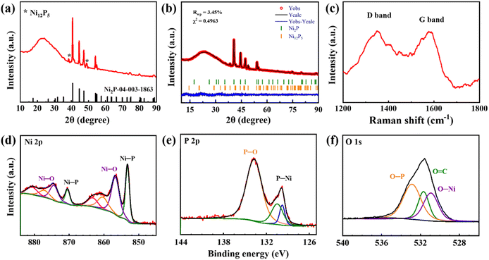 | ||
| Fig. 1 XRD pattern (a), Rietveld refinement of XRD pattern (b), Raman spectrum (c), Ni 2p (d), P 2p (e), and O 1s (f) XPS spectra of prepared NixP/C fiber mat. Adapted from ref. 25. | ||
Raman spectroscopy in Fig. 1c further characterizes the NixP/C composite by revealing the carbon structure. The ID/IG ratio of 1.00 suggests a high graphitization level, indicating well-ordered carbon within the nanofibers. This graphitized carbon network is crucial for providing electronic conductivity across the interlayer, facilitating charge transfer and supporting the material's role in lithium–sulfur batteries. The content of carbon, according to CHNS analysis, is 36.1 wt%.
XPS analysis confirms the composition of the surface oxidation layer on the NixP/C nanofibers, specifically examining the Ni 2p, P 2p, and O 1s spectra. The Ni 2p peaks at 870.5 eV (Ni 2p1/2) and 853.2 eV (Ni 2p3/2) in Fig. 1d, along with P 2p peaks at 130.4 eV (2p1/2) and 129.7 eV (2p3/2) in Fig. 1e, verify the presence of nickel phosphide, confirming the intended composition of the interlayer. Additional Ni–O peaks at 874.2 eV and 856.7 eV indicate a thin surface oxidation layer, typical for metal phosphides exposed to air. The molar ratio of Ni–O to Ni–P, calculated as 1.37, supports the controlled surface oxidation level, balancing structural stability and polysulfide retention for lithium–sulfur battery applications. The P 2p spectrum also reveals a P–O band at 133.7 eV, characteristic of phosphate species, which may contribute to forming Li3PO4 in situ during battery operation. Li3PO4 serves as an ionic conductor, facilitating lithium-ion transport while stabilizing polysulfides on the interlayer's surface.
In the O 1s spectrum in Fig. 1f, the presence of O–Ni, O![[double bond, length as m-dash]](https://www.rsc.org/images/entities/char_e001.gif) C, and O–P at 530, 531.5, and 533 eV, respectively, confirms the complex nature of the surface oxidation layer. The high intensity of P–O relative to C
C, and O–P at 530, 531.5, and 533 eV, respectively, confirms the complex nature of the surface oxidation layer. The high intensity of P–O relative to C![[double bond, length as m-dash]](https://www.rsc.org/images/entities/char_e001.gif) O in NixP/C suggests an optimized surface composition, minimizing undesired C
O in NixP/C suggests an optimized surface composition, minimizing undesired C![[double bond, length as m-dash]](https://www.rsc.org/images/entities/char_e001.gif) O interactions with polysulfides and enhancing lithium-ion diffusion and polysulfide retention.
O interactions with polysulfides and enhancing lithium-ion diffusion and polysulfide retention.
Fig. 2a shows the SEM images of the NixP/C composite nanofibers, confirming the fibrous structure with a uniform distribution of nanoparticles attached to the nanofibers. Further microstructural analysis by TEM (Fig. 2b) reveals that in NixP/C, nanoparticles are not only present on the surface but are also evenly dispersed throughout the interior of the nanofibers. The nanoparticles, with an average diameter of approximately 35 nm, are uniformly spread across the nanofiber matrix.
 | ||
| Fig. 2 Surface SEM (a), TEM (b), and HR-TEM (c) images of prepared NixP/C fiber mat. Inset: HR-TEM image with a lattice spacing. Adapted from ref. 25. | ||
The HR-TEM image (Fig. 2c) shows a thin and uniform oxidation layer around the NixP nanoparticles. The d-spacing of the main lattice fringes of the NixP nanoparticle, as shown in the inset of Fig. 2c, is measured to be 0.22 nm, corresponding to the (111) plane of Ni2P with a hexagonal crystal structure and space group P62m.
These results verify the formation of NixP, the graphitized carbon structure, and the composition of the surface oxidation layer in NixP/C nanofibers. These features are anticipated to make the NixP/C composite an effective interlayer for lithium–sulfur batteries, providing enhanced electronic conductivity, improved polysulfide management, and greater electrochemical stability.
3.2 Polysulfide adsorption and conversion tests for NixP/C fiber mat
The thickness of the interlayer plays a crucial role in balancing catalytic activity, polysulfide trapping efficiency, and overall cell stability in lithium–sulfur batteries. In this study, the NixP/C interlayer thickness was fixed at 80 μm, as confirmed from the cross-sectional SEM image in Fig. 3a. Prior research with different interlayers, for example, demonstrated that thicker interlayers (e.g., 100 μm) enhance initial capacities due to improved polysulfide trapping; however, this benefit often comes at the cost of accelerated electrode degradation. Conversely, thinner interlayers (e.g., ∼50 μm) may stabilize capacity retention, though potentially at the expense of initial catalytic efficiency.26 The selection of 80 μm for the NixP/C interlayer thus represents a strategic compromise to optimize catalytic performance and polysulfide trapping without incurring rapid degradation.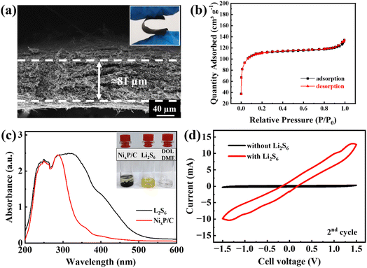 | ||
| Fig. 3 Cross-sectional SEM (a), inset: digital image of flexibility, N2 adsorption–desorption isotherms (b) of the NixP/C fiber mat (reproduced from ref. 25), UV-vis spectra after polysulfide adsorption test (c), inset: digital images of vials for polysulfide adsorption test, CV curves of symmetric cells with the NixP/C fiber mats (d). | ||
Flexibility is another crucial characteristic for the interlayer in lithium–sulfur batteries, as this layer must withstand mechanical stress and deformation during battery operation. Over repeated charge–discharge cycles, mechanical stresses can compromise structural integrity if the interlayer lacks adequate flexibility. Thus, evaluating and demonstrating this flexibility is essential for ensuring long-term battery stability and performance.27 In this study, an optical image of the NixP/C fiber mat interlayer was captured after it was bent to assess its structural response to mechanical stress. The image in the inset of Fig. 3a shows the interlayer retaining its integrity without visible cracks or fractures, which demonstrates its flexibility and resilience. This observation indicates that the NixP/C fiber mat is well-suited to function as a durable and flexible interlayer, reducing the risk of mechanical failure and supporting reliable battery performance even under repeated cycling.
As reported earlier, it has relatively high specific surface area of 354 m2 g−1 (Fig. 3b) and abundant pores of different sizes.25 Consequently, after 30 minutes of inserting this NixP/C fiber mat into lithium polysulfide solution, a strong decolorization is observed (inset of Fig. 1c) due to the adsorption of lithium polysulfides, as residual solution after the adsorption test demonstrates no characteristic peaks of lithium polysulfides between 300 and 500 nm wavelength on UV-vis spectrum in Fig. 3c.
Fig. 3d shows CV curves of the symmetric cells assembled with prepared NixP/C fiber mats with Li2S6-containing and Li2S6-free electrolyte solutions. Appearance of high-intensity oxidation-reduction peaks on the curve of the cell with lithium polysulfides implies catalytic effect of the prepared NixP/C fiber mats towards conversion of lithium polysulfides.28 Thus, in the second cycle, the reduction process begins with the conversion of elemental sulfur (S8), formed in the previous cycle, into intermediate lithium polysulfides (Li2Sx). The first cathodic peak at −0.9 V corresponds to the initial reduction of S8 to soluble lithium polysulfides (Li2Sx), while the subsequent peak at −1.3 V represents further reduction of these lithium polysulfide intermediates to form insoluble Li2S/Li2S2. During the anodic scan, the peaks at +0.9 V and +1.3 V correspond to the oxidation processes. These peaks indicate the gradual re-oxidation of Li2S/Li2S2 back into higher-order lithium polysulfides, ultimately reforming elemental sulfur (S8).
Maintaining electrochemical neutrality in lithium–sulfur batteries is essential to avoid unwanted lithiation and delithiation of the fiber mats, which could interfere with the performance of sulfur cathode. In this setup, when assembled with lithium and a standard electrolyte (1 M LiTFSI in DOL/DME = 1/1 + 0.1 M LiNO3), the fiber mats showed no plateaus in the potential profile (Fig. S1a†) and delivered minimal capacity (Fig. S1b†). This lack of activity within the 1.85–2.8 V vs. Li/Li+ range confirms their electrochemical inactivity, allowing the sulfur cathode to operate without interference from the mats. By remaining inert, the fiber mats help maintain a stable electrochemical environment, essential for improving cell longevity and performance.
3.3 Effect of NixP/C on electrochemical properties of lithium–sulfur batteries
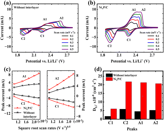
The CV curves at different scan rates ranging from 0.1 to 0.5 mV s−1 in Fig. 4a and b highlight the impact of the NixP/C fiber mat interlayer on the electrochemical performance of GPC@S|Li cells. Both configurations exhibit characteristic cathodic (C1, C2) and anodic (A1, A2) peaks associated with sulfur redox reactions at low scan rates, but notable differences arise at higher scan rates. In the cell without the interlayer, the merging of A1 and A2 peaks suggests slower reaction kinetics and increased polarization. In contrast, the cell with the NixP/C interlayer shows sharper, more distinct peaks with cathodic peaks shifted to higher potentials, indicating enhanced reaction kinetics and reduced overpotential. This improvement can be attributed to the interlayer's ability to trap polysulfides, mitigate the shuttle effect, and enhance ion and electron transport, leading to more efficient sulfur utilization and better overall battery performance.29As demonstrated in Fig. 4c, the linear correlation between peak currents and the square root of scan rates indicates a diffusion-controlled mechanism, consistent with the Randles–Sevcik equation (eqn (1)):30
| Ip = 2.69 × 10⁵ × n1.5 × A × DLi+0.5 × CLi+ × v0.5 | (1) |
The calculated DLi+ in the cell with NixP/C as interlayer is almost four times higher than that without interlayer at every oxidation–reduction step, as summarized in Fig. 4d.
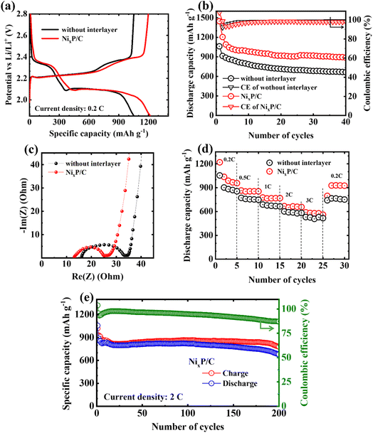
Fig. 5a shows initial potential profiles of cells with and without interlayer within a potential range of 1.85–2.8 V vs. Li/Li+. The cell with interlayer exhibits more prolonged potential plateau, delivering higher initial discharge and charge capacities of around 1200 mA h g−1, respectively. In contrast, the cell without interlayer has the initial discharge capacity of only 1050 mA h g−1. As a result of prevention of the shuttle of lithium polysulfides and their catalytic conversion, more stable capacity retention up to 40 cycles at 0.2C is observed for the cell with interlayer (Fig. 5b).
To further explore the influence of the lower cutoff potential, the electrochemical performance of cells with and without the interlayer was compared by lowering the cutoff down to 1.7 V vs. Li/Li+ (Fig. S2†). At this lower potential, the initial capacity of the cell with the interlayer was significantly enhanced, indicating greater polysulfide utilization at deeper discharge levels (Fig. S2a†). However, while the initial capacity increased, there was no significant improvement in capacity retention across cycling (Fig. S2b†). Importantly, the coulombic efficiency trends diverged: without the interlayer, cells showed a gradual decline in coulombic efficiency after 30 cycles, whereas cells with the interlayer maintained stable efficiency up to 100 cycles (Fig. S2c†). These results underscore that while a lower cutoff potential can increase initial capacity, the addition of an interlayer has a more pronounced effect on maintaining stable coulombic efficiency and cyclability. Thus, a cutoff of 1.85 V vs. Li/Li+ was chosen as an optimal balance, minimizing potential side reactions associated with deeper discharge and preserving the electrochemical stability of the interlayer, which supports extended cell longevity and stability.
Considering the relatively high electrical conductivity of the prepared NixP/C fiber mat (7.89 S cm−1),25 when inserted as the interlayer, it can serve as an additional upper current collector and improve the electronic path to the sulfur cathode, decreasing the charge-transfer resistance in the cell, as confirmed from the smaller diameter of the semicircle in the Nyquist plots of cells in Fig. 5c.
Although no significant difference in the rate-capability trends is observed after the introduction of the interlayer into the cell structure in Fig. 5d, the cell with interlayer was able to maintain slightly higher discharge capacities. Moreover, when the current density returned back from high (3C) to low (0.2C), the incorporated interlayer helped sulfur cathode to preserve much more capacity (by ∼200 mA h g−1) than the referred counterpart. When tested at a high current density of 2C, the cell with interlayer exhibited stable capacity retention up to almost 200 cycles with an average discharge capacity of about 800 mA h g−1, as shown in Fig. 5e.
3.4 Polysulfide trapping mechanism of NixP/C fiber mat
The interaction between polysulfides and the NixP/C interlayer with a tailored surface oxidation layer is essential for enhancing lithium–sulfur battery stability. For polar materials like nickel phosphide, polysulfide interactions are often mediated by oxidation layers, resulting in interfacial species such as thiosulfate (S2O32−).31 To understand these interaction mechanisms, XPS analysis was conducted on the cathode side of the NixP/C interlayer after the 5th discharge and 5th charge at 0.2C in a lithium–sulfur cell. In the S 2p spectra in Fig. 6a, S2O32− species were observed at around 167–165 eV for both cases,26 likely formed during initial cycles by the oxidation layer and persisting as a stable interfacial phase on the NixP/C interlayer. This stable interfacial compound enables an effective polysulfide trapping mechanism. Acting as a bridge, it allows the NixP/C interlayer to capture polysulfides transiently, such as Li2S2/Li2S species observed at 158.5 eV and 160.0 eV,31 during charging (that could otherwise be deposited on the lithium anode, causing irreversible parasitic reactions), while still allowing their controlled release and reoxidation, which is confirmed by their absence after the discharge. This reversible process aids in sulfur cycling, mitigating the shuttle effect, promoting efficient polysulfide capture, stabilization, and gradual release throughout cycling, which is key to sulfur retention and long-term efficiency in lithium–sulfur batteries.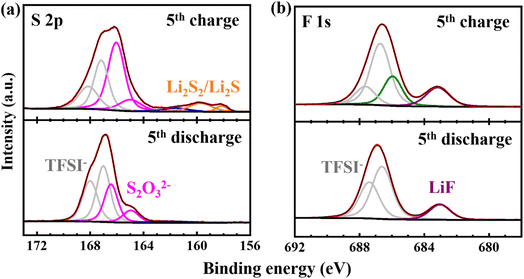 | ||
| Fig. 6 S 2p (a) and F 1s (b) XPS spectra of the cathode side of the NixP/C interlayer after the 5th discharge and 5th charge at 0.2C in a lithium–sulfur cell. | ||
The F 1s spectra in Fig. 6b provide additional insights into the interfacial stabilization afforded by the NixP/C interlayer, evidenced by a consistent LiF peak at approximately 683.5 eV in both charge and discharge states.32 The continuous presence of LiF in both states suggests that the NixP/C interlayer, with its tailored oxidation layer, promotes durable interphase formation. This LiF component likely complements the S2O32− observed in the S 2p spectra, with both phases contributing to a stable, multifunctional interface. While S2O32− anchors polysulfides, aiding reversible sulfur cycling, LiF offers physical and chemical stability to the interlayer, blocking polysulfide migration toward the anode. These interfacial components support the role of the NixP/C interlayer in maintaining a stable, polysulfide-trapping environment, enhancing sulfur retention, minimizing capacity fade, and improving overall lithium–sulfur battery performance.
The surface of the interlayer on both cathode and separator sides was further studied after 100 cycles at 0.2C in the potential range of 1.7–2.8 V vs. Li/Li+ (sample from Fig. S2†) and presented in Fig. 7, offering key insights into its functionality in a lithium–sulfur battery. On the cathode side (Fig. 7a), sulfur deposits and electrode mass accumulation are observed between the fibrous voids, indicating that the interlayer effectively traps dissolved polysulfides. This behavior is critical for preventing polysulfides from dissolving into the electrolyte, which would degrade battery performance by allowing active material loss and electrolyte contamination. The deposition of sulfur on the fibrous surface also suggests that the interlayer increases the surface area for reactions, promoting sulfur utilization and improving reaction kinetics.
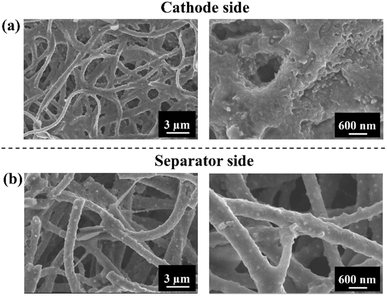 | ||
| Fig. 7 FE-SEM images of the cathode side (a) and separator side (b) of the NixP/C interlayer after cycling at 0.2C. | ||
In contrast, Fig. 7b shows that the fibrous structure of the interlayer remains intact on the separator side, confirming its role in blocking polysulfide migration to the anode. This prevention of the polysulfide shuttle effect protects the anode from being passivated by lithium sulfide formation, which would otherwise result in capacity fade and diminished performance. The preserved structure on the anode side highlights the efficiency of the interlayer in maintaining battery stability.
By facilitating sulfur deposition and trapping polysulfides on the cathode side, the interlayer not only mitigates polysulfide migration but also expands the reactive surface area, enhancing the overall reaction rate. This dual functionality—trapping active material and acting as an extension of the cathode—contributes to better sulfur utilization and improved cycling performance.
These results confirm the ability of the NixP/C interlayer to trap polysulfides and catalyze their conversion to final products of electrochemical reactions, enhancing overall electrochemical performance of lithium–sulfur batteries.
4. Conclusions
Nickel phosphide carbon composite fiber mats with tailored surface oxidation layer exhibited strong polysulfide adsorption properties and catalytic properties towards their conversion to final products of electrochemical reactions. As a result, when applied as interlayer in lithium–sulfur cell with bio-waste-derived graphene-like carbon-based sulfur cathode, they considerably improved the electrochemical performance by increasing the charge–discharge capacities and reducing the charge-transfer resistance. Post-mortem analyses revealed effective entrapment of polysulfides followed by their mediated conversion and deposition on the cathode side, restricting their further dissolution and shuttle to the anode side. This in turn ensured excellent cycle stability up to 200 cycles at 2C, keeping a high discharge capacity of about 800 mA h g−1. The underlying mechanism behind the performance improvement lies in the formation of S2O32−-and LiF-rich stable interphase, facilitated by the surface oxidation layer on the NixP/C interlayer. These results confirmed the applicability of the nickel phosphide carbon composite nanofibers to lithium–sulfur cells of diverse configurations, highlighting their potential in the advancement of lithium–sulfur battery technologies.Data availability
Part of the data on the physical characteristics of the prepared NixP/C interlayers is available at https://doi.org/10.1016/j.jpowsour.2024.234933.Conflicts of interest
There are no conflicts to declare.Acknowledgements
This research was funded by the research targeted program BR21882402 “Development of new material technologies and energy storage systems for a green economy” and project AP13068219 “Development of multifunctional free-standing carbon composite nanofiber mats” from the Ministry of Science and Higher Education of the Republic of Kazakhstan.References
- A. Eftekhari and D. W. Kim, J. Mater. Chem. A, 2017, 5, 17734–17776 RSC.
- M. Liu, X. Qin, Y. B. He, B. Li and F. Kang, J. Mater. Chem. A, 2017, 5, 5222–5234 RSC.
- Z. F. Wang, H. Y. Wang, X. L. Liu, Y. X. Chen, Y. Zhao, Y. G. Zhang, Q. Q. Han, C. L. Qin, Z. Bakenov, Y. C. Wang and X. Wang, Rare Met., 2023, 42, 3705–3717 CrossRef CAS.
- R. B. LingHu, J. X. Chen, J. H. Zhang, B. Q. Li, Q. S. Fu, G. Kalimuldina, G. Z. Sun, Y. Han and L. Kong, J. Energy Chem., 2024, 93, 663–668 CrossRef CAS.
- X. Liang, C. Hart, Q. Pang, A. Garsuch, T. Weiss and L. F. Nazar, Nat. Commun., 2015, 6, 1–8 Search PubMed.
- K. Tan, Z. Tan, S. Liu, G. Zhao, Y. Liu, L. Hou and C. Yuan, J. Mater. Chem. A, 2023, 11, 2233–2245 RSC.
- L. Fan, M. Li, X. Li, W. Xiao, Z. Chen and J. Lu, Joule, 2019, 3, 361–386 CrossRef CAS.
- T. Yang, X. Tian, Y. Song, S. Wu, J. Wu and Z. Liu, Appl. Surf. Sci., 2023, 611, 155690 CrossRef CAS.
- Y. Liu, X. Qin, S. Zhang, G. Liang, F. Kang, G. Chen and B. Li, ACS Appl. Mater. Interfaces, 2018, 10, 26264–26273 CrossRef CAS PubMed.
- G. Liang, J. Wu, X. Qin, M. Liu, Q. Li, Y.-B. He, J.-K. Kim, B. Li and F. Kang, ACS Appl. Mater. Interfaces, 2016, 8, 23105–23113 CrossRef CAS.
- A. Belgibayeva, Z. Kawate and I. Taniguchi, Mater. Lett., 2021, 291, 129595 CrossRef CAS.
- A. Belgibayeva, Y. Zhuang and I. Taniguchi, Mater. Lett., 2024, 374, 137134 CrossRef CAS.
- F. Sultanov, N. Zhumasheva, A. Dangaliyeva, A. Zhaisanova, N. Baikalov, B. Tatykayev, M. Yeleuov, Z. Bakenov and A. Mentbayeva, J. Power Sources, 2024, 593, 233959 CrossRef CAS.
- H. Song, C. Zuo, X. Xu, Y. Wan, L. Wang, D. Zhou and Z. Chen, RSC Adv., 2018, 8, 429–434 RSC.
- L. Chen, H. Yu, W. Li, M. Dirican, Y. Liu and X. Zhang, J. Mater. Chem. A, 2020, 8, 10709–10735 RSC.
- B. Guan, X. Gao, Z. Wang and K. Sun, Nanoscale, 2024, 16, 11005–11018 RSC.
- Y. Niu, W. Feng, Z. Lei, W. Hu, X. Zheng, W. Su and L. Zhang, J. Electroanal. Chem., 2023, 946, 117743 CrossRef CAS.
- X. Wang, H. M. Kim, Y. Xiao and Y. K. Sun, J. Mater. Chem. A, 2016, 4, 14915–14931 RSC.
- J. Li, Z. Xiong, Y. Wu, H. Li, X. Liu, H. Peng, Y. Zheng, Q. Zhang and Q. Liu, J. Energy Chem., 2022, 73, 513–532 CrossRef CAS.
- H. Yuan, X. Chen, G. Zhou, W. Zhang, J. Luo, H. Huang, Y. Gan, C. Liang, Y. Xia, J. Zhang, J. Wang and X. Tao, ACS Energy Lett., 2017, 2, 1711–1719 CrossRef CAS.
- K. M. Yang, S. Kim, K. Yang, S. choi, M. Cho and Y. Lee, J. Electrochem. Soc., 2021, 168, 120513 CrossRef CAS.
- Z. Guang, Y. Huang, X. Chen, X. Sun, M. Wang, X. Feng, C. Chen and X. Liu, Electrochim. Acta, 2019, 307, 260–268 CrossRef CAS.
- S. Yang, R. Xiao, T. Hu, X. Fan, R. Xu, Z. Sun, B. Zhong, X. Guo and F. Li, Nano Energy, 2021, 90, 106584 CrossRef CAS.
- Y. Zhong, L. Yin, P. He, W. Liu, Z. Wu and H. Wang, J. Am. Chem. Soc., 2018, 140, 1455–1459 CrossRef CAS PubMed.
- G. Turarova, I. Taniguchi, Z. Bakenov and A. Belgibayeva, J. Power Sources, 2024, 613, 234933 CrossRef CAS.
- A. Belgibayeva and I. Taniguchi, J. Power Sources, 2021, 484, 229308 CrossRef CAS.
- G. Zhao, S. Liu, X. Zhang, Y. Zhang, H. Shi, Y. Liu, L. Hou and C. Yuan, J. Mater. Chem. A, 2022, 11, 1856–1865 RSC.
- Y. Liu, X. Gao, M. Shen, Y. Zhao, X. Zhang, S. Liu, X. Liu, L. Hou and C. Yuan, Angew. Chem., 2024, e202412898 Search PubMed.
- S. Erol, in Nanostructured Materials for Lithium/Sulfur Batteries, ed. G. Amadou Belal and T. Sabu, Springer, 2024, vol. 156, pp. 29–50 Search PubMed.
- X. Gao, D. Zhou, Y. Chen, W. Wu, D. Su, B. Li and G. Wang, Commun. Chem., 2019, 2, 66 CrossRef.
- Z. Wang, Y. Yan, Y. Zhang, Y. Chen, X. Peng, X. Wang, W. Zhao, C. Qin, Q. Liu, X. Liu and Z. Chen, Carbon Energy, 2023, 5, e306 CrossRef CAS.
- X. Liu, T. Diemant, A. Mariani, X. Dong, M. E. Di Pietro, A. Mele and S. Passerini, Adv. Mater., 2022, 34, 2207155 CrossRef CAS.
Footnote |
| † Electronic supplementary information (ESI) available. See DOI: https://doi.org/10.1039/d4ra07285e |
| This journal is © The Royal Society of Chemistry 2024 |

