 Open Access Article
Hierarchical NiCo2O4@CuS composite electrode with enhanced surface area for high-performance hybrid supercapacitors†
Chandu V. V. Muralee Gopi a,
Dasha Kumar Kulurumotlakatla
 b,
K. V. G. Raghavendrac,
Maduru Suneetha*d and
R. Ramesh
 *e
*e
aDepartment of Electrical Engineering, University of Sharjah, Sharjah, P. O. Box 27272, United Arab Emirates
bGraduate School of Convergence Science, Pusan National University, San 30 Jangjeon-dong, Geumjeong-gu, Busan 609-735, Republic of Korea
cDepartment of Electrical Engineering, Pusan National University, Busan, Republic of South Korea
dSchool of Chemical Engineering, Yeungnam University, 280 Daehak-Ro, Gyeongsan, Gyeongbuk 38541, Republic of Korea. E-mail: msunithachem@gmail.com
eDepartment of Chemical Engineering, School of Mechanical, Chemical and Materials Engineering, Adama Science and Technology University, P. O. Box 1888, Adama, Ethiopia. E-mail: ramesh.redrouthu@astu.edu.et
First published on 23rd December 2024
Abstract
Hierarchical binder-free NiCo2O4@CuS composite electrodes have been successfully fabricated on a nickel foam surface using a facile hydrothermal method and directly used as a battery-type electrode material for supercapacitor applications. The surface morphological studies reveal that the composite electrode exhibited porous NiCo2O4 nanograss-like structures with CuS nanostructures. The surface area of the composite is significantly enhanced (91.38 m2 g−1) compared to NiCo2O4 (52.16 m2 g−1), with a predominant pore size of 3–6 nm. This synergistic combination enhanced the electrode's electrochemical properties. The NiCo2O4@CuS electrode delivered an impressive specific capacitance of 141.13 mA h g−1 at 1 A g−1, surpassing the performance of the bare NiCo2O4 electrode. The composite electrode also exhibited excellent rate capability and cycling stability, retaining 87.49% of its initial capacity at high current densities and 88.62% after 3000 cycles. A hybrid supercapacitor (HSC) device assembled using NiCo2O4@CuS and G-ink electrodes attained a peak energy density of 28.85 W h kg−1 at a power density of 238.2 W kg−1, outperforming many reported HSCs. Additionally, the HSC device demonstrated exceptional cycling stability, retaining 87.59% of its initial capacitance after 4000 cycles. The superior performance of the NiCo2O4@CuS composite electrode is attributed to the synergistic combination of NiCo2O4 and CuS, which promotes interfacial electron separation and facilitates rapid electron transfer.
1 Introduction
As the world handles the pressing issues of global warming and depletion of fossil fuel reserves, harnessing and storing renewable energy sources has become a critical priority.1,2 While supercapacitors hold immense promise owing to their exceptional power density and ability to charge and discharge rapidly, their widespread adoption has been hindered by the significant limitation of lower energy density compared to traditional batteries.3–5 Novel designs are crucial for expanding the vast applications of supercapacitors (SCs) and meeting the diverse needs of energy storage.6 In this context, hybrid supercapacitors (HSCs) have emerged as a rapidly growing and promising class of SCs. They offer a compelling combination of high-power density, long cycle life, and significantly enhanced energy density compared to conventional SCs.7 This enhanced energy density makes them particularly attractive for applications requiring fast charging/discharging and substantial energy storage capacity.Generally, HSCs typically combine two distinct electrodes: an electric double-layer capacitor (EDLC) electrode as an anode and a pseudocapacitive/battery-like electrode (i.e., faradaic redox materials) as a cathode.8 This unique combination bridges the gap between traditional SCs and batteries, offering high power and improved energy density. However, the energy storage performance of HSCs mainly depends on the properties of their electrode materials.9,10 Therefore, researchers are actively exploring novel nanostructured materials with well-defined architectures, high surface areas, abundant active sites, and superior redox chemistry to unlock the full potential of HSCs.11 EDLCs store charge through electrostatic interactions, while battery-like materials rely on faradaic redox reactions.12 Carbon materials like activated carbon and reduced graphene oxide dominate EDLCs due to their stability and wide potential range.13 However, battery-type materials like NiCo2O4, Co3O4, Ni(OH)2, and NiS offer much higher energy storage because of their redox reactions with electrolyte ions.14 Therefore, designing promising electrode materials for hybrid supercapacitors is a promising approach to boost energy density.
Transition-metal oxides, particularly those derived from ruthenium, manganese, copper, nickel, and cobalt, are playing an increasingly critical role in the development of supercapacitors.15 Among various metal oxides, battery-type NiCo2O4 stands out as a highly promising candidate for HSCs due to the advantages of environmental friendliness, ease of synthesis, cost-effectiveness, scalability, and superior performance, which make it an attractive choice for next-generation energy storage solutions.16 While NiCo2O4 boasts several advantages for supercapacitors, but its performance is hindered by the sluggish ion transport associated with cobalt-based oxides. This limitation restricts the material's ability to exploit its potential for high-energy storage.17 Researchers have developed a novel approach to fabricate NiCo2O4/metal sulfide composite electrodes for HSC applications to address this issue. Recently, transition metal sulfides emerged as a promising new generation of pseudocapacitive/battery-type electrode materials for supercapacitors, offering several advantages over traditional oxides, which are abundant redox-active centers, improved energy and power density, and enhanced catalytic activity.18 Therefore, by combining the advantages of NiCo2O4 and metal sulfides, strategic integration of NiCo2O4 with metal sulfides offers a promising approach to enhance the energy storage performance of HSCs further.
Recently, Wang et al. fabricated a NiCo2O4@CoS core/shell nanowire array electrode using hydrothermal and electrodeposition techniques and delivered an excellent specific capacitance of 1902.5 F g−1 at 1 A g−1.19 In a previous study, Chu and colleagues fabricated a novel core–shell structure of nickel sulfide (Ni–S) nanoparticles deposited onto nickel cobalt oxide (NiCo2O4) nanoplates.20 This hierarchical material demonstrated exceptional performance as a supercapacitor electrode, exhibiting a high areal capacitance of 1.85 F cm−2 at 8 mA cm−2. In a recent study, Wang et al. fabricated NiCo2O4/NiCo2S4 nanoarrays on Ni foam, achieving a high specific capacitance (3176 F g−1 at 2 A g−1) through a novel interface ion-exchange strategy.21 Zhu et al. synthesized core–shell Co9S8@NiCo2O4 nanoneedles on carbon fibers, achieving high specific capacitance (1022.5 F g−1 at 1 A g−1) for supercapacitors.22 Deng et al. prepared Ni3S2/NiCo2O4 core–shell flake arrays on Ni foam using a combined hydrothermal and electrodeposition method and obtained a high specific capacity (1201 C g−1 at 1 mA cm−2).23
Inspired by the above works, in the present work, CuS is deposited on the NiCo2O4 surface to achieve a high-performance electrode material for HSC applications. CuS, a unique p-type semiconductor with a narrow bandgap, finds diverse applications in energy storage, photocatalysis, and electrocatalysis due to its high electronic conductivity (∼10−3 S cm−1) exceeding most metal oxides and richer redox chemistry compared to carbon materials, contributing to high specific capacitance.24 Hence, the combination of NiCo2O4 and CuS may create a heterogeneous interface that promotes interfacial electron separation and facilitates rapid electron transfer, contributing to excellent electrochemical properties. As a result, in the present work, we successfully fabricated a NiCo2O4@CuS electrode with a hierarchical structure using a multistep process. This composite features CuS nanostructures grown on porous NiCo2O4 nanograss-like structures. The unique structure offers several advantages, including a high surface area and short diffusion pathways for ions, contributing to enhanced supercapacitor performance compared to NiCo2O4 electrode material alone. Therefore, the hierarchical NiCo2O4@CuS nanocomposite holds promise as a high-performance electrode material for supercapacitor applications.
2. Experimental section
To conduct the experiment, commercially available analytical-grade chemical reagents were acquired from Sigma-Aldrich Co., Ltd. The G-ink was obtained from MExplorer Co., Ltd. These reagents were used without further purification.2.1. Preparation of NiCo2O4 electroactive material on Ni foam substrate
NiCo2O4 material was synthesized directly onto nickel (Ni) foam without a binder using a hydrothermal process. Before deposition, in an ultrasonic bath, 1 cm × 2 cm Ni foam pieces underwent thorough cleaning with 3 M HCl, acetone, ethanol, and deionized (DI) water, each for 15 minutes. The NiCo2O4 precursor solution was prepared by mixing 0.05 M Ni(NO3)2·6H2O, 0.1 M Co(NO3)2·6H2O, 0.24 M CH4N2O, and 0.12 M NH4F in 60 mL of DI water and stirring for 30 min. The Ni foam was thoroughly cleaned and then immersed in a precursor solution. The mixture was sealed within a 100 mL Teflon-lined autoclave and heated at 100 °C for 6 h. Post-cooling, the electrodes were cleaned using ethanol and deionized water before being dried overnight at 60 °C. A subsequent heat treatment at 200 °C for 2 h resulted in the final NiCo2O4 product.2.2. Preparation of NiCo2O4@CuS electrode material
In a typical synthesis, 0.05 M Cu(NO3)2·6H2O and 0.1 M CH4N2S are stirred thoroughly in 70 mL DI water. The pre-loaded NiCo2O4 material on Ni foam was placed inside CuS solution containing a Teflon-lined autoclave. The autoclave was sealed and heated to 100 °C for 2 h. Once cooled to ambient temperature, the Ni foam electrodes were cleaned with ethanol and DI water. The electrodes were placed in a drying oven at 60 °C for 2 h to ensure complete dryness. The approximate mass of NiCo2O4 and NiCo2O4@CuS material deposited on the Ni foam was determined to be 1.9 mg cm−2 and 2.1 mg cm−2, respectively.2.3. Characterizations
The surface morphology, crystalline structure, phase purity, elemental composition and surface area of the electrodes are characterized by field emission scanning electron microscopy (FE-SEM, Hitachi S4800), X-ray diffraction (XRD, Cu Kα radiation D8 ADVANCE), X-ray spectroscopy (XPS, ESCALAB 250), and Brunauer–Emmett–Teller (BET, ASAP 2020), respectively.Electrochemical performance was assessed using a Bio-Logic SP-150 potentiostat. Three-electrode electrochemical measurements were carried out in a 3 M KOH aqueous solution. The prepared NiCo2O4@CuS (or NiCo2O4) served as the working electrode, while Ag/AgCl and platinum wire were employed as the reference and counter electrodes, respectively. The specific capacity (QSC, mA h g−1) was calculated based on the equation:25
 | (1) |
3 Results and discussion
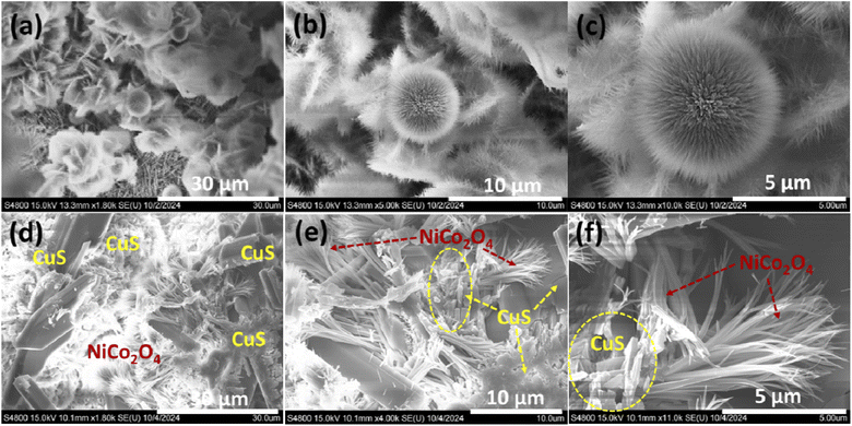
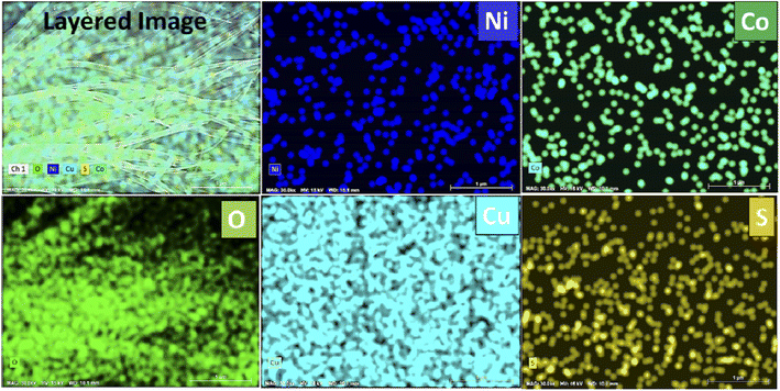
The surface morphologies of bare Ni foam, NiCo2O4-coated Ni foam, and NiCo2O4@CuS-coated Ni foam were characterized using FE-SEM. As shown in Fig. S1,† bare Ni foam images clearly depict the porous three-dimensional network structure of the Ni-foam, which serves as an ideal substrate for the growth of the NiCo2O4 and NiCo2O4@CuS composite. As depicted in Fig. 1a–c, NiCo2O4 displayed a distinctive dandelion-like structure with numerous sharp nanoneedles radiating outward from the center. This arrangement created abundant open spaces with dandelion-like structures. FE-SEM images of the NiCo2O4@CuS composite heterostructures on Ni foam at varying magnifications are shown in Fig. 1d–f. The images demonstrate a uniform coverage of the Ni foam surface by the NiCo2O4@CuS composite material (Fig. 1d). Fig. 1e and f highlight the unique nanostructure of the composite, consisting of nanograss-like NiCo2O4 structures and interspersed irregular CuS nanostructures. The NiCo2O4@CuS nanostructures were characterized by a porous structure composed of numerous nanocrystallites. The mesoporous architecture enhances electrolyte penetration and facilitates effective charge transfer, thereby improving the electrochemical performance of the material when used as a supercapacitor electrode.Additionally, energy-dispersive X-ray spectroscopy (EDS) mapping analysis of the as-prepared NiCo2O4@CuS composite electrode (Fig. 2) confirms the uniform distribution of all constituent elements, including Ni, Co, O, Cu, and S. This homogeneous elemental composition is indicative of a well-integrated and synergistic interaction between the NiCo2O4 and CuS components.
The phase and crystal structure of the as-prepared electrodes were determined using XRD analysis. Fig. 3a presents the XRD pattern of the NiCo2O4 and NiCo2O4@CuS materials on the Ni foam. Both electrodes display three prominent and distinct diffraction peaks corresponding to the Ni foam substrate. Additionally, peaks observed at 2θ angles of 18.74°, 31.53°, 36.53°, 42.49°, 55.81°, 58.54°, and 64.42° can be unambiguously attributed to the (111), (220), (311), (400), (422), (511), (440) planes of the NiCo2O4 cubic phase (JCPDS # 20-0781), respectively.26 The XRD analysis revealed the presence of NiCo2O4 and CuS phases in the NiCo2O4@CuS composite grown on Ni foam. Except for the peak at 42.49°, all the other NiCo2O4 peaks are observed in the NiCo2O4@CuS composite electrode. Additionally, the composite exhibited the peaks at 29.05°, 31.93°, 32.84°, and 47.71° matched the (102), (103), (006), and (110) crystal planes of CuS hexagonal phase (JCPDS # 06-0464).27 The absence of any additional peaks confirms the purity of the synthesized materials. This XRD pattern confirms the successful growth of the NiCo2O4@CuS composite on the Ni foam substrate.
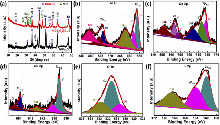 | ||
| Fig. 3 (a) XRD spectra of the as-prepared electrodes. High-resolution XPS spectra of (b) Ni 2p, (c) Co 2p, (d) Cu 2p, (e) O 1s, and (f) S 2p. | ||
The chemical composition and elemental bonding of the newly prepared NiCo2O4@CuS composite electrode were investigated using XPS. The survey spectra, as shown in Fig. S2,† clearly identify the presence of Ni, Co, Cu, O, and S elements within the composite material. The high-resolution-XPS (HR-XPS) Ni 2p spectrum of NiCo2O4@CuS in Fig. 3b exhibits four distinct peaks corresponding to Ni 2p1/2 and Ni 2p3/2, along with two satellite (Sat.) peaks. The peaks located at 873.81 eV (Ni 2p1/2) and 856.24 eV (Ni 2p3/2) are attributed to the presence of Ni2+ ions, while the peaks at 875.71 eV (Ni 2p1/2) and 857.91 eV (Ni 2p3/2) are indicative of Ni3+ ions. Fig. 3c reveals the HR-XPS Co 2p spectrum, which exhibits two distinct satellite peaks with two primary peaks corresponding to Co 2p3/2 and Co 2p1/2, respectively. Notably, the fitting peaks centered around 780.99 eV and 796.44 eV indicate a Co3+ oxidation state, while those at 783.09 eV and 798.41 eV suggest the presence of Co2+. The HR-XPS Cu 2p spectrum displays a single satellite peak accompanied by two primary peaks corresponding to Cu 2p3/2 and Cu 2p1/2 (Fig. 3d). Upon deconvolution, the peaks centered at 933.56 and 936.66 eV are attributed to Cu1+ and Cu2+ in the Cu 2p3/2 region, respectively. Similarly, the Cu 2p1/2 peaks can be resolved into Cu1+ at 953.41 eV and Cu2+ at 955.82 eV. The high-resolution O 1s spectrum exhibited three distinct peaks centered at 530.66 eV, 531.58 eV, and 532.89 eV, which were attributed to the presence of lattice oxygen (Ni–Co–O), oxygen in hydroxyl groups (–OH), and physically adsorbed water (H2O), respectively (Fig. 3d).28 As shown in Fig. 3e, the presence of two spin–orbit peaks at 161.92 eV (2p3/2) and 163.93 eV (2p1/2) in the high-resolution S 2p spectrum indicates the formation of Cu–S bonds, confirming the successful synthesis of copper sulfide. Furthermore, a peak observed at 168.69 eV is associated with sulfur oxides due to air oxidation.29
The performance of these as-fabricated electrodes is significantly influenced by the structural properties of their electrode materials, particularly the specific surface area and pore size distribution.30 The BET method and pore size distribution analysis provide valuable insights into these critical parameters, enabling the optimization of supercapacitor performance. The specific surface area and pore size distribution of the NiCo2O4 and NiCo2O4@CuS composite were analyzed through nitrogen adsorption–desorption isotherms, as shown in Fig. 4. Both materials exhibited a type IV isotherm, indicating the presence of mesopores.31 Introducing CuS to the surface of NiCo2O4 resulted in a substantial enhancement of the specific surface area. While the bare NiCo2O4 exhibited a surface area of 52.16 m2 g−1, incorporating CuS led to a significant increase, reaching 91.38 m2 g−1. The increased porosity provides more accessible active sites for electrolyte ions, potentially leading to improved electrochemical performance. To further elucidate the pore structure of the NiCo2O4 and NiCo2O4@CuS electrodes, Barrett–Joyner–Halenda (BJH) pore size distribution analysis was conducted. The resulting plots, depicted in the inset of Fig. 4, reveal that the predominant pore sizes for both materials fall within the mesoporous range, specifically between 3 and 6 nm. This mesoporous architecture is advantageous for supercapacitor applications as it balances ion diffusion and electrolyte accessibility, facilitating efficient charge storage and transport within the electrode materials.32
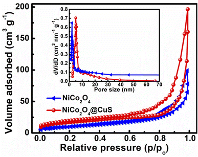 | ||
| Fig. 4 N2 adsorption–desorption isotherm of the bare NiCo2O4 and NiCo2O4@CuS composite electrodes. The inset shows the BJH pore size distribution. | ||
The fabricated electrodes were evaluated for their electrochemical properties using a three-electrode configuration in a 3 M KOH electrolyte. Fig. 5a compares the cyclic voltammetry (CV) plots of both bare NiCo2O4 and NiCo2O4@CuS composite electrodes at 5 mV s−1 scan rate and a potential range of 0–0.6 V. Both electrodes showcase prominent redox peaks with significant current responses, signifying their battery-like behavior, which are distinct from those of EDLCs. A Faraday reaction may occur within the electrolyte solution is as follows:
| NiCo2O4 + H2O + OH− → NiOOH + 2CoOOH + e− | (2) |
| CoOOH + OH− → CoO2 + H2O + e− | (3) |
| CuS + OH− ↔ CuSOH + e− | (4) |
| CuSOH + OH− ↔ CuSO + H2O + e− | (5) |
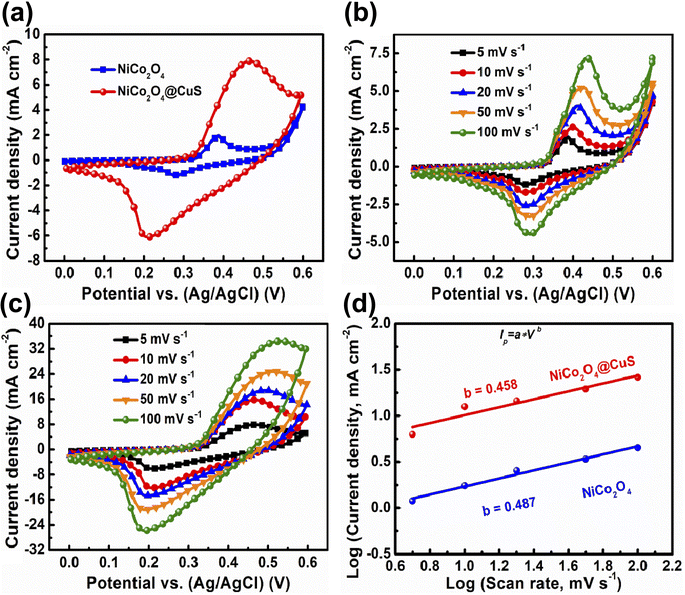 | ||
| Fig. 5 (a) Comparative CV curves of the as-prepared electrodes at 5 mV s−1. CV plots of (b) bare NiCo2O4 and (c) NiCo2O4@CuS composite electrode. (d) Relationship between the log(ip) and log(v). | ||
The NiCo2O4@CuS composite electrode displayed a significantly larger area enclosed by its cyclic voltammetry curve and higher peak currents than the bare NiCo2O4 electrode. This indicates a greater charge storage capacity in the composite electrode due to the increased presence of electroactive sites that facilitate rapid electrochemical reactions. Fig. 5(b) and (c) present the cyclic voltammetry (CV) curves of NiCo2O4 and NiCo2O4@CuS electrodes, respectively, at varying scan rates from 5 to 100 mV s−1 within a potential range of 0.0 to 0.6 V. Notably, both electrode materials displayed multiple redox peaks across all scan rates, suggesting that the charge storage mechanism primarily involves faradaic redox reactions. The increased scan rate shifted the oxidation and reduction peak potentials to more positive and negative values, respectively, due to the electrode material's internal resistance.33 In addition, the simultaneous enlargement of peak current density and enclosed area of CV curves with increasing scan rate, without altering the CV shape, signifies the excellent electrochemical reversibility of the material.
To better understand the charge storage properties of the prepared electrodes, we investigated the relationship between peak cathodic current (ip) and scan rate (v) by a power-law equation (ip = avb). This equation helps distinguish between diffusion-controlled (battery-like) and surface-controlled (capacitor-like) behavior. The slope of the log(ν) − log(ip) plot yields the b value, which suggests diffusion-dominant behavior if it is close to 0.5 and surface-controlled behavior if it is near 1. The charge storage mechanisms in the bare NiCo2O4 and NiCo2O4@CuS electrodes are predominantly diffusion-controlled, as indicated by their b-values of 0.487 and 0.458, respectively, which are closer to 0.5 (Fig. 5d). Our findings are consistent with prior research examining similar battery-type materials.34,35
The relative contributions of capacitive and diffusion-controlled charge storage mechanisms in the synthesized electrodes can be precisely quantified using the below equation:36
| ip = k1v + k2v1/2 | (6) |
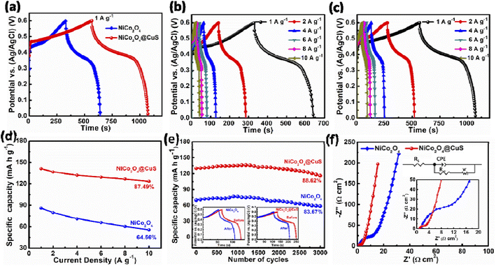
To further demonstrate the improved capacity of the NiCo2O4@CuS composite electrode, galvanostatic charge–discharge (GCD) measurements were performed in a 3-electrode configuration. Fig. 7a shows the GCD curves of both electrodes at a constant current density of 1 A g−1. As expected for battery-type materials, both curves exhibit non-linear discharge profiles, unlike those of pure EDLC electrodes. The composite electrode displayed significantly longer charge–discharge times than the bare NiCo2O4 electrode, confirming the CV analysis findings. This enhanced performance can be attributed to the deposition of CuS on the surface of NiCo2O4 and the higher mass loading of active material, which provides more electroactive sites for redox reactions. Fig. 7b and c further demonstrate the battery-like behavior of both electrodes at various current densities. The non-linear charge–discharge profiles and clear plateaus indicate good reversibility and faradaic efficiency. Using the GCD curves and eqn (1), Fig. 7d plots the specific capacity of each electrode at different current densities. The composite NiCo2O4@CuS electrode delivers higher capacities compared to the bare NiCo2O4 electrode, reaching 141.13 mA h g−1 at 1 A g−1 compared to 86.01 mA h g−1 for the bare electrode. Furthermore, the composite electrode exhibits superior rate capability, retaining 87.49% of its capacity even at high current densities. This is significantly better than the 64.56% retention of the bare electrode. The impressive performance of the hybrid electrode can be ascribed to the incorporation of CuS onto the NiCo2O4 surface, which significantly boosts the electrode's conductivity, enhances its surface area, and creates plentiful electroactive sites for improved charge storage and transfer. The NiCo2O4 and composite NiCo2O4@CuS electrode's cycling stability was evaluated at 4 A g−1 for 3000 charge–discharge cycles, as shown in Fig. 7e. The NiCo2O4@CuS electrode delivers higher cycling stability (88.62%) than the bare NiCo2O4 electrode (83.67%) over 3000 cycles. Even though there is a higher cycling life than NiCo2O4, the NiCo2O4@CuS specific capacity gradually decreased over the cycling process due to the gradual oxidation of the CuS component within the electrode material when exposed to the alkaline electrolyte.37
Table 1 compares different synthesis methods and electrochemical properties of various composite electrodes. The data shows that the NiCo2O4@CuS electrode outperforms recently reported metal oxide@metal sulfide-based composites regarding energy storage capacity. This superior performance can be attributed to three key factors: (i) the direct growth of NiCo2O4 onto the Ni foam substrate improves electron transport within the electrode, facilitating the movement of electrolyte ions; (ii) the uniform deposition of NiCo2O4 creates numerous active sites for charge storage, leading to a higher overall capacity; (iii) the deposition of CuS on the surface of NiCo2O4 allows electrolyte ions to penetrate more easily into the interior of the electrode, promoting faster charge diffusion and further enhancing energy storage performance.
| Electrode material | Synthesis method | Specific capacity (mA h g−1) | Cycling stability (cycles) | Ref. |
|---|---|---|---|---|
| NiO/NiS | Hydrothermal | 75.19 at 1 A g−1 | 97.6% (4000) | 38 |
| MnNi2O4-PbS | Hydrothermal | 163.4 at 1 A g−1 | 98.9% (4000) | 39 |
| Co3O4@CoS | Electrodeposition | 127.36 at 1 A g−1 | 78.1% (5000) | 40 |
| NiFe2O4/MoS2 | Hydrothermal | 63.25 at 1 A g−1 | 90.7% (3000) | 41 |
| MoS2-Co3O4 | Laser ablation in liquids | 69 at 0.5 A g−1 | 87% (500) | 42 |
| ZnO/NiS | Chemical bath deposition and hydrothermal | 89.5 at 1.5 A g−1 | 74.6% (5000) | 43 |
| ZnO/CoS2 | Hydrothermal | 111.2 at 1 A g−1 | 74.6% (4000) | 44 |
| CuCo2O4/CuS | Hydrothermal and thermolysis | 102.1 at 1 A g−1 | — | 45 |
| NiO/NiS@CNT | 112.5 at 1 A g−1 | 100% (20![[thin space (1/6-em)]](https://www.rsc.org/images/entities/char_2009.gif) 000) 000) |
46 | |
| NiCo2O4@CuS | Hydrothermal | 141.13 at 1 A g−1 | 88.62% (3000) | This work |
The electrical properties of both NiCo2O4@CuS and NiCo2O4 electrodes were analyzed using electrochemical impedance spectroscopy (EIS) in a frequency range of 100 kHz to 0.01 Hz, with a small amplitude of 5 mV. The Nyquist plot in Fig. 7f shows a small semicircle at high frequencies, indicative of charge-transfer resistance (Rct). A linear portion at low frequencies represents the ion diffusion resistance. The intersection of the plot with the real axis at high frequencies indicates the equivalent series resistance (RS). The inset of Fig. 7f includes magnified plots of the electrode and an equivalent circuit that can be used to fit the Nyquist plots. In the low-frequency region, the slope of the line for the NiCo2O4@CuS electrode is closer to the vertical axis than that of the CuS electrode. This indicates a lower ion diffusion impedance, suggesting better ionic transport within the composite material. Furthermore, the NiCo2O4@CuS composite electrode exhibits smaller values for both the RS = 0.91 Ω cm2 and Rct = 2.03 Ω cm2 values compared to the bare NiCo2O4 (RS = 1.12 Ω cm2 and Rct = 10.35 Ω cm2) electrode. These lower RS and Rct promote improved electrical conductivity and faster charge transfer within the composite electrode.
Before fabricating a HSC device, it is crucial to ensure that the electrodes have an equal charge distribution. This balance can be achieved by adhering to the following equation:
 | (7) |
To achieve a high energy density in HSCs, the mass ratio of the anode to the cathode was determined to be approximately 0.7187 based on charge balance considerations.
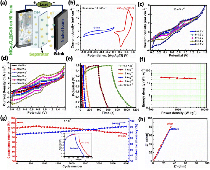
The negative electrode of the HSC was constructed by applying a commercially accessible G-ink slurry onto the surface of Ni foam and subsequently drying the coated material overnight at 100 °C. The prepared NiCo2O4@CuS on Ni foam (cathode) was paired with the G-ink electrode (anode) using a cellulose paper separator and 3 M KOH aqueous electrolyte to assemble the complete HSC (Fig. 8a). The electrochemical properties of the G-ink deposited on a Ni foam electrode were assessed using a three-electrode configuration, with the results illustrated in Fig. S3.† The specific capacitance (CSC), energy density (E), and power density (P) of the HSC were determined from the GCD curve using the following equations:47,48
 | (8) |
 | (9) |
 | (10) |
The negative electrode, G-ink, functioned within a voltage range of −1.0 to 0 V, while the positive electrode, NiCo2O4@CuS composite, operated between 0 and 0.6 V. This pairing yielded a total operating voltage of 0 to 1.6 V for the high-energy HSC, as shown in Fig. 8b. The CV results in Fig. 8c show that the optimal operating potential for the device is 0 to 1.6 V. This was determined by testing different potential windows, ranging from 0 to 0.8 V, 0 to 1.0 V, 0 to 1.2 V, 0 to 1.4 V, and 0 to 1.6 V. Fig. 8d illustrates the CV profiles of the HSC within a potential range of 0 to 1.6 V at various scan rates. The observed CV curves suggest that the energy storage process in this material involves both faradaic and capacitive contributions. This is evident from the curves' shape, which exhibit reversible peaks (characteristic of faradaic processes) and a rectangular-like background (indicative of capacitive behavior). As the scan rate increases, the CV curves exhibit redox peaks while maintaining a consistent shape, indicating excellent reversibility. Further, Fig. 8e illustrates the GCD profiles of the HSC at various current densities. The GCD plots exhibited non-linear, approximately symmetrical charge–discharge profiles, indicating excellent rate capability. The specific capacitance of the HSC was determined to be 145.33, 138.04, 134.15, 129.95, 127.72, and 124.13 F g−1 at current densities of 0.5, 1, 2, 4, 6, and 10 A g−1, respectively. This demonstrates a commendable rate capability, retaining 85.32%.
To evaluate the feasibility of the HSCs for practical applications, their energy and power densities were determined from the GCD plots. These metrics provide valuable insights into the device's performance for real-world applications. The fabricated device exhibits a peak energy density of 28.85 W h kg−1 at a power density of 238.2 W kg−1, as illustrated in the Ragone plot of Fig. 8f. Moreover, it sustains an energy density of 22.78 W h kg−1 at a maximum power density of 4403 W kg−1. Our novel NiCo2O4@CuS//G-ink HSC device delivers an energy density that is either higher or on par with other reported HSC devices, MoS2 nanowires/NiCo2O4 nanosheets//activated carbon (AC) (18.4 W h kg−1 at 1200.2 W kg−1),49 NiCo2O4/Co3S4//AC (14.0 W h kg−1 at 400 W kg−1),50 MgCo2O4@Ni3S2//AC (28.37 W h kg−1 at 159.6 W kg−1),51 NiS/NiO//AC (17.42 W h kg−1 at 4000 W kg−1),52 NiO@CNTs@CuO//AC (26.32 W h kg−1 at 219.03 W kg−1),53 NiSe2/CuO//AC (29 W h kg−1 at 1200 W kg−1),54 and NiCo2O4@NiCo2S//AC (35.6 W h kg−1 at 1500 W kg−1),55 respectively.
The cycling stability of HSCs is essential for their practical use. Fig. 8g shows the device's long-term cycling performance and coulombic efficiency at a current density of 4 A g−1. The HSC exhibited excellent cycling stability, retaining 87.59% of its initial capacitance and maintaining a high coulombic efficiency of 90.8% even after 4000 cycles. This exceptional performance indicates the device's remarkable reversibility and suitability for practical applications. The assembled HSC exhibited remarkable stability, as evidenced by the minimal changes in EIS plots before and after cycling tests (Fig. 8h). The exceptional cycling stability and performance of the HSC device are achieved through the synergistic effect of the NiCo2O4@CuS composite and G-ink-based material.
4. Conclusions
The successful fabrication of a hierarchical NiCo2O4@CuS composite electrode for high-performance supercapacitors is reported. The unique morphology of the composite, characterized by CuS nanostructures grown on porous NiCo2O4 nanograss-like structures, offers a high surface area and short diffusion pathways for ions, enhancing electrolyte penetration and facilitating charge transfer. The composite electrode demonstrated superior specific capacitance, rate capability, and cycling stability compared to the pristine NiCo2O4 electrode. EIS analysis further confirmed that the composite exhibited lower RS and Rct compared to the bare NiCo2O4 electrode, indicating improved electrical conductivity and faster charge transfer. An assembled HSC device using NiCo2O4@CuS and G-ink electrodes exhibited an impressive energy density of 28.85 W h kg−1 at a power density of 238.2 W kg−1, surpassing many reported HSCs. Moreover, the device exhibited excellent cycling stability, retaining 87.59% of its initial capacitance after 4000 cycles. The exceptional performance of the NiCo2O4@CuS electrode highlights its potential for practical applications in energy storage systems. Future research efforts should focus on further optimizing the electrode material and exploring alternative electrode combinations to achieve even higher energy and power densities.Data availability
The data supporting this study's findings are available from the corresponding author upon reasonable request.Author contributions
Chandu V. V. Muralee Gopi: writing – original draft, conceptualization, methodology, formal analysis, investigation, writing – review & editing; Dasha Kumar Kulurumotlakatla: investigation, methodology; Kummara Venkata Guru Raghavendra: investigation, methodology; M. Suneetha: funding, conceptualization, methodology, formal analysis, investigation, supervision, validation; R. Ramesh: funding, conceptualization, methodology, formal analysis, investigation, supervision, validation.Conflicts of interest
The authors declare that they have no known competing financial interests or personal relationships that could have appeared to influence the work reported in this paper.Acknowledgements
This work was supported by the National Research Foundation of Korea (NRF) (Grant No. RS-2022-00166999). Also, this work is supported by the Adama Science and Technology University.References
- Y. H. Cai, C. Y. Zhao, L. J. Zhao, X. H. Zhang and J. X. Wang, J. Solid State Chem., 2022, 316, 123581 CrossRef.
- Z. Y. Peng, L. Y. Gong, J. Huang, Y. Wang, L. C. Tan and Y. W. Chen, Carbon, 2019, 153, 531 CrossRef.
- O. Gerard, A. Numan, S. Krishnan, M. Khalid, R. Subramaniam and R. Kasi, J. Energy Storage, 2022, 50, 104283 CrossRef.
- Y. K. Sonia, S. Srivastav and S. K. Meher, Langmuir, 2023, 39, 9111 CrossRef.
- B. Pant, G. P. Ojha, J. Acharya and M. Park, Int. J. Hydrogen Energy, 2023, 48, 37001 CrossRef.
- S. Nagamuthu, S. Vijayakumar, S.-H. Lee and K.-S. Ryu, Appl. Surf. Sci., 2016, 390, 202 CrossRef.
- F. Sun, J. Gao, X. Liu, L. Wang, Y. Yang, X. Pi, S. Wu and Y. Qin, Electrochim. Acta, 2016, 213, 626 CrossRef.
- D. P. Dubal, O. Ayyad, V. Ruiz and P. Gómez-Romero, Chem. Soc. Rev., 2015, 44, 1777–1790 RSC.
- S. C. Sekhar, G. Nagaraju and J. S. Yu, Nano Energy, 2017, 36, 58 CrossRef.
- D. P. Chatterjee and A. K. Nandi, J. Mater. Chem. A, 2021, 9, 15880–15918 RSC.
- W. Wei, S. Cui, L. Ding, L. Mi, W. Chen and X. Hu, ACS Appl. Mater. Interfaces, 2017, 9, 40655 CrossRef CAS.
- P. Simon and Y. Gogotsi, Nat. Mater., 2008, 7, 845 CrossRef.
- L. L. Zhang and X. S. Zhao, Chem. Soc. Rev., 2009, 38, 2520 RSC.
- H. Liu, X. Liu, S. Wang, H.-K. Liu and L. Li, Energy Storage Mater., 2020, 28, 122 CrossRef.
- C. An, Y. Zhang, H. Guo and Y. Wang, Nanoscale Adv., 2019, 1, 4644 RSC.
- W. Jiang, F. Hu, Q. Yan and X. Wu, Inorg. Chem. Front., 2017, 4, 1642 RSC.
- J. Jiang, Y. Li, J. Liu, X. Huang, C. Yuan and X. W. Lou, Adv. Mater., 2012, 24, 5166 CrossRef.
- R. Barik and P. P. Ingole, Curr. Opin. Electrochem., 2020, 21, 327 CrossRef.
- W. D. Wang, X. F. Li, P. P. Zhang, B. Q. Wang, S. H. Gong, X. C. Wang, F. Liu and J. P. Cheng, J. Electroanal. Chem., 2021, 891, 115257 CrossRef.
- Q. X. Chu, W. Wang, X. F. Wang, B. Yang, X. Y. Liu and J. H. Chen, J. Power Sources, 2015, 276, 19 CrossRef.
- X. D. Hong, X. Wang, J. W. Fu, Y. Li and B. Liang, Electrochim. Acta, 2021, 385, 138437 CrossRef.
- F. F. Zhu, W. J. Liu, Y. Liu and W. D. Shi, Inorg. Chem. Front., 2019, 6, 982 RSC.
- X. L. Deng, Y. Fan, Q. X. Zhou, H. F. Huang, W. Z. Zhou, Z. Q. Lan, X. Q. Liang, G. X. Li, J. Guo and S. L. Tang, Electrochim. Acta, 2019, 319, 783 CrossRef.
- S. Sun, P. Li, S. Liang and Z. Yang, Nanoscale, 2017, 9, 11357 RSC.
- C. V. V. M. Gopi, P. J. S. Rana, R. Padma, R. Vinodh and H. J. Kim, J. Mater. Chem. A, 2019, 7, 6374 RSC.
- S. Khalid, C. Cao, L. Wang and Y. Zhu, Sci. Rep., 2016, 6, 22699 CrossRef PubMed.
- Y. Cui, J. Zhang, G. Li, Y. Sun, G. Zhang and W. Zheng, Chem. Eng. J., 2017, 325, 424 CrossRef.
- L. Xu, Q. Jiang, Z. Xiao, X. Li, J. Huo, S. Wang and L. Dai, Angew. Chem., Int. Ed., 2016, 128, 5363 CrossRef.
- T. Wang, W. Ma, Y. Zhang, J. Guo, T. Li, S. Wang and D. A. Yang, J. Energy Storage, 2021, 35, 102319 CrossRef.
- S. Kondrat, C. R. Pérez, V. Presser, Y. Gogotsi and A. A. Kornyshev, Energy Environ. Sci., 2012, 5, 6474 RSC.
- L. Yu, W. Wang, L. Gu, Y. Wang, Y. Ying, Y. Mao, L. Sun and X. Peng, ACS Appl. Mater. Interfaces, 2013, 5, 9850 CrossRef PubMed.
- G. Li, M. Jing, Z. Chen, B. He, M. Zhou and Z. Hou, RSC Adv., 2017, 7, 10376 RSC.
- S. C. Sekhar, G. Nagaraju and J. S. Yu, Nano Energy, 2018, 48, 81–92 CrossRef.
- B. Y. Guan, A. Kushima, L. Yu, S. Li, J. Li and X. W. D. Lou, Adv. Mater., 2017, 29, 1605902 CrossRef PubMed.
- S. Yang, Z. Han, J. Sun, X. Yang, X. Hu, C. Li and B. Cao, Electrochim. Acta, 2018, 268, 20 CrossRef.
- C. Ren, et al., Adv. Funct. Mater., 2020, 30, 2004519 CrossRef.
- G. He, M. Qiao, W. Li, Y. Lu, T. Zhao, R. Zou, B. Li, J. A. Darr, J. Hu, M. M. Titirici and I. P. S. Parkin, Adv. Sci., 2017, 4, 1600214 CrossRef PubMed.
- S. Y. Kim, C. V. V. M. Gopi, A. E. Reddy and H. J. Kim, New J. Chem., 2018, 42, 5309 RSC.
- T. Y. Park, C. V. M. Gopi, J. W. Ahn and H. J. Kim, New J. Chem., 2018, 42, 14157–14162 RSC.
- J. Ning, T. Zhang, Y. He, C. Jia, P. Saha and Q. Cheng, Mater. Horiz., 2017, 10, 608 Search PubMed.
- Y. Zhao, L. Xu, J. Yan, W. Yan, C. Wu, J. Lian, Y. Huang, J. Bao, J. Qiu, L. Xu, Y. Xu, H. Xu and H. Li, J. Alloys Compd., 2017, 726, 608–617 CrossRef.
- D. W. Liang, Z. F. Tian, J. Liu, Y. X. Ye, S. L. Wu, Y. Y. Cai and C. H. Liang, Electrochim. Acta, 2015, 182, 376–382 CrossRef.
- S. S. Rao, J. Energy Storage, 2020, 28, 101199 CrossRef.
- I. K. Durga, K. V. G. Raghavendra, N. B. Kundakarla, S. Alapati, J. W. Ahn and S. S. Rao, Energies, 2021, 14, 4925 CrossRef.
- Z. K. Heiba, M. A. Deyab, M. B. Mohamed, N. M. Farag, A. M. El-naggar and J. R. Plaisier, Appl. Phys. A, 2021, 127, 853 CrossRef.
- Y. Zheng, Y. Tian, S. Liu, X. Tan, S. Wang and Q. Guo, et al., J. Alloys Compd., 2019, 806, 170–179 CrossRef.
- C. V. V. M. Gopi, R. Vinodh, S. Sambasivam, I. M. Obaidat, S. Singh and H. J. Kim, Chem. Eng. J., 2020, 381, 122640 CrossRef.
- C. V. V. M. Gopi, P. J. S. Rana, R. Padma, R. Vinodh and H. J. Kim, J. Mater. Chem. A, 2019, 7, 6374–6386 RSC.
- S. Wen, Y. Liu, F. Zhu, R. Shao and W. Xu, Appl. Surf. Sci., 2018, 428, 616–622 CrossRef.
- Y. Liu, S. Wen and W. Shi, Mater. Lett., 2018, 214, 194–197 CrossRef.
- W. He, M. Pang, S. Jiang, H. Yang, R. Wang, N. Li, Q. Pan, J. Li and J. Zhao, Synth. Met., 2022, 285, 117021 CrossRef.
- H. Wang, J. Wang, M. Liang, Z. He, K. Li, W. Song, S. Tian, W. Duan, Y. Zhao and Z. Miao, ACS Omega, 2021, 6, 17999–18007 CrossRef PubMed.
- G. Nagaraju, S. M. Cha, S. C. Sekhar and J. S. Yu, Adv. Energy Mater., 2017, 8, 1702201 CrossRef.
- A. U. Khan, K. Tahir, H. M. A. Hassan, K. Albalawi, Q. U. Khan, A. Khan, M. M. Moharam, S. Latif, M. S. Refat and A. M. Aldawsari, J. Electroanal. Chem., 2022, 920, 116624 CrossRef CAS.
- H. Rong, T. Chen, R. Shi, Y. Zhang and Z. Wang, ACS Omega, 2018, 3, 5634–5642 CrossRef.
Footnote |
| † Electronic supplementary information (ESI) available. See DOI: https://doi.org/10.1039/d4ra07808j |
| This journal is © The Royal Society of Chemistry 2024 |

