 Open Access Article
Bismuth nanoparticles embedded in carbon fibers as flexible and free-standing anodes for efficient sodium ion batteries†
Yang Caoa,
Shiwei Wei *b,
Huifang Zhangb,
Yong Yanb,
Zhiling Pengb and
Heming Zhao*b
aSchool of Materials Science and Engineering, North University of China, Taiyuan, 030051, China
bShanxi Key Laboratory of High-end Equipment Reliability Technology, School of Mechanical and Electrical Engineering, North University of China, Taiyuan, 030051, China. E-mail: wei_swe@163.com; zhm@nuc.edu.cn
First published on 19th December 2024
Abstract
Metallic bismuth is a promising anode electrode material for sodium ion batteries due to its high theoretical specific capacity. However, the formation of Na3Bi during the reaction process brings about significant volume changes and structural collapse of the electrode, resulting in the destruction of structures and a decrease in the cycling stability of sodium ion batteries. In this study, bismuth nanoparticles embedded in carbon fibers (Bi/CF) through a facile approach of electrospinning and calcination. Bi nanoparticles with diameters of approximately 20 nm were homogeneously dispersed in the carbon fibers, as confirmed by relevant morphological and structural features. The carbon fiber substrate can serve as a flexible and free-standing electrode, forming a conductive network to accelerate electron transport and ion diffusion. In light of this, Bi/CF anodes exhibit a high reversible capacity (376.6 mA h g−1 at 0.1 A g−1) and long-term cycle stability (only attenuates 0.12% in each cycle after 2000 times). This work provides a convenient and effective strategy for the synthesis of flexible and free-standing anodes for high-performance sodium ion batteries.
1. Introduction
In the face of the increasing energy demand and severe environmental issues, sodium ion batteries (SIBs) have emerged as promising alternatives to lithium ion batteries (LIBs) in large-scale energy storage systems, mainly because of their abundant resources and the low cost of precursors.1,2 The properties of cathode and anode electrode materials generally determine the overall electrical characteristics of the battery. As an excellent anode, graphite is widely used in lithium-ion batteries, but it is not suitable for sodium-ion batteries.3 The mismatch between graphite and sodium ions leads to a rapid decrease in the cycle life of batteries and poor long-term stability, which is the biggest technical obstacle to the development of SIBs. Hence, there is an urgent necessity to make breakthroughs in discovering suitable anode materials for SIBs.Over the past few decades, numerous materials have been explored and tested to serve as anodes for SIBs. Examples include carbonaceous composites (hard carbon, carbon nanowires and microtubes);4,5 metallic elements (such as Sn and Sb);6 metal oxides and sulfides (like NaxMO2, NaxNiO2, MoS2, SnS2);7,8 as well as other materials like MXene composites9,10 and so on. Among them, Sb and Sn are attractive due to the high theoretical capacities of 660 mA h g−1 and 874 mA h g−1, respectively. However, one major drawback is that the large volume expansions (up to 390% for Sb and up to 420% for Sn) charge during sodiation/desodiation. The relevant studies on Sn/CF and Sb/CF also demonstrate this point.11 As one of the periodic table group V elements, bismuth has received widespread attention due to its high capacity (386 mA h g−1) and relatively small volume expansions (∼244%) with sodium. For example, Chen et al. designed a mangosteen-like bismuth nanospheres coated with N-doped carbon shell (Bi@NC) anode for SIBs.12 The Bi@NC electrode exhibits high capacity and outstanding cycling stability (96.5%, 1000 cycles). Additionally, Zhu et al. embeds bismuth nanoparticles on graphene nanosheets for the study of long-life sodium storage.13 Based on a unique combination method, the Bi/Go electrode can achieve a reversible capacity of 122 mA h g−1 at a current density of 4 A g−1 for 9500 cycles. The high volumetric capacity characteristic of bismuth renders it a potential anode material for sodium ion batteries. However, there are still some issues with bismuth anodes, such as poor conductivity of bismuth and large volume changes during sodium ion insertion/extraction, which limit the further development of bismuth electrodes. Therefore, the novel design of electrode microstructure is a reasonable approach to address the volume expansion, electron transport, and cycling stability issues of SIBs.
Compared with some previous research works, the innovation of this work lies in that extremely small bismuth nanoparticles are uniformly anchored in interlaced carbon fibers through a facile approach of electrospinning and calcination, forming a flexible and free-standing composite electrode (Bi/CF). Nano bismuth particles are uniformly and tightly dispersed inside carbon fibers, which is beneficial for increasing the specific surface area and active sites of the active material. Carbon fibers construct a conductive network that facilitates the transfer of sodium ions and improves the utilization efficiency of bismuth. Benefiting from the synergistic effect between fine bismuth particles and interlaced carbon fibers, the active sites inside the composite electrode material have increased, resulting in an accelerated migration rate of ions and electrons. Therefore, the Bi/CF electrodes present excellent electrochemical characteristics of high discharge capacity and long-term cycling life as the anode in SIBs.
2. Experimental section
2.1 Materials preparation
Typically, 0.5 g of polyacrylonitrile (PAN, Mw = 250![[thin space (1/6-em)]](https://www.rsc.org/images/entities/char_2009.gif) 000) was added to 4 mL of dimethylformamide (DMF) and dissolved uniformly under magnetic stirring. Subsequently, 0.2 g of Bi(NO)3·5H2O powder was added to the above solution, followed by stirring and ultrasonic treatment for 30 min to form a spinning solution. The electrospinning machine was adjusted to a voltage of 20 kV, with a distance of 15 cm between the needle and the drum receiver and spun for 2 h to form a composite film. Pre oxidize the above film in air at a heating rate of 2 °C min−1 for 2 h at 220 °C, and finally heat it to 700 °C under a flowing nitrogen atmosphere and kept it for 2 h to form a composite electrode film of Bi and carbon fiber, named as Bi/CF. As for comparison, pure metal bismuth powder was mixed with acetylene black and PVDF in a ratio of 8
000) was added to 4 mL of dimethylformamide (DMF) and dissolved uniformly under magnetic stirring. Subsequently, 0.2 g of Bi(NO)3·5H2O powder was added to the above solution, followed by stirring and ultrasonic treatment for 30 min to form a spinning solution. The electrospinning machine was adjusted to a voltage of 20 kV, with a distance of 15 cm between the needle and the drum receiver and spun for 2 h to form a composite film. Pre oxidize the above film in air at a heating rate of 2 °C min−1 for 2 h at 220 °C, and finally heat it to 700 °C under a flowing nitrogen atmosphere and kept it for 2 h to form a composite electrode film of Bi and carbon fiber, named as Bi/CF. As for comparison, pure metal bismuth powder was mixed with acetylene black and PVDF in a ratio of 8![[thin space (1/6-em)]](https://www.rsc.org/images/entities/char_2009.gif) :
:![[thin space (1/6-em)]](https://www.rsc.org/images/entities/char_2009.gif) 1
1![[thin space (1/6-em)]](https://www.rsc.org/images/entities/char_2009.gif) :
:![[thin space (1/6-em)]](https://www.rsc.org/images/entities/char_2009.gif) 1 to prepare electrode sheets with a loading of ca. 2 mg using the traditional slurry method and marked as pure Bi.
1 to prepare electrode sheets with a loading of ca. 2 mg using the traditional slurry method and marked as pure Bi.
2.2 Materials characterization
X-ray diffraction (XRD, DX-2700) was utilized for the crystal structures analysis of samples with Cu Kα radiation (λ = 1.5406 Å) at 40 kV and 30 mA. Field-emission scanning electron microscope (FESEM, Hitachi S-4800) and transmission electron microscope (TEM, JEM-2100PLUS) were used to observe the morphology and microstructure of samples. X-ray photoelectrons (XPS, ESCLAB 250Xi) was performed to detected the Elemental composition and valence state of the samples.2.3 Electrochemical measurements
The prepared Bi/CF electrode is punched into circular pieces with a diameter of 14 mm and a weight of approximately 2 mg, which are used as flexible self-supporting electrodes for the anode of sodium ion batteries. In a glove box filled with argon gas protection, Bi/CF serves as the anode electrode, metal sodium foil is matched as the counter electrode, glass microfiber (Whatman® GF/D) is used as the separator and 1.0 M NaPF6 dissolved in DME (dimethyl ether) is worked as the electrolyte to assemble CR2032 coin type sodium ion batteries. The electrochemical workstation (CS-2350H, CORRTEST) is used for the measurement of cyclic voltammetry (CV) and electrochemical impedance spectroscopy (EIS). The LAND battery measurement system is adapted to test the constant current charging and discharging cycle performance of batteries between 0.01 V and 1.5 V.3. Results and discussion
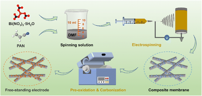
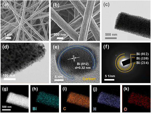
The schematic diagram of the preparation process for the Bi/CF electrode is depicted in Fig. 1. An appropriate amount of PAN is dissolved in DMF solution and mixed with ultrasonically dispersed Bi(NO3)3·5H2O to form a spinning solution. Under a specific spinning environment, the spinning solution is spun into a composite membrane. After the pre-oxidation process, the morphology of the PAN fiber membrane is basically fixed (as shown in Fig. S1†). In the subsequent carbonization process, Bi/CF with flexible and free-standing structure is formed through the carbonization reaction of PAN and the decomposition reaction of bismuth nitrate. The flexibility characteristic testing of Bi/CF electrode is presented in Fig. S2 and S3.† It can be observed that the flexible Bi/CF electrode can be bent in reverse and folded without breaking. Meanwhile, the SEM image and XRD spectrogram of bent Bi/CF electrode are shown in Fig. S4,† which confirm that the flexible electrode remains structurally intact under mechanical stress.The microstructure of the as-obtained Bi/CF electrode is presented by the SEM images in Fig. 2(a) and (b). The interlaced structure of carbon fibers can be clearly observed, and the fibers are evenly distributed in thickness, with a diameter of approximately 500 nm. It can be observed from the TEM images of Fig. 2(c) and (d) that the bismuth nanoparticles dispersed inside the carbon fibers and tightly intertwined with each other to form Bi/CF electrodes. As observed, most of the spherical bismuth nanoparticles homogenously embedded on and around the fibers while a few nanoparticles stuck to the surface. This is attributed to the reaction between bismuth nitrate and carbon during high-temperature carbonization, forming uniformly distributed bismuth nanoparticles. The synergistic effect of carbon fiber and bismuth particles is beneficial for the improvement of electrode performance. The conductive network of carbon fiber ensures faster electrolyte transport while dispersed bismuth nanoparticles can be exposed more active sites for sodium. As shown in the HRTEM image of Fig. 2(e), there exists clear boundaries between bismuth nanoparticles and surrounded carbon of Bi/CF. Bismuth nanospheres are firmly anchored and enwrapped by carbon fibers and the fringes of bismuth correspond to the crystal plane of (012). Fig. 2(f) presents the corresponding selected area electron diffraction (SAED) pattern, where the diffraction rings can be indexed to the (012), (110), and (214) crystal planes of Bi. Furthermore, the energy dispersive X-ray spectroscopy (EDX) spectrum and corresponding mapping images shown in Fig. 2(g)–(k) indicate the uniformly distribution of Bi, C, N and O elements in the Bi/CF electrode.
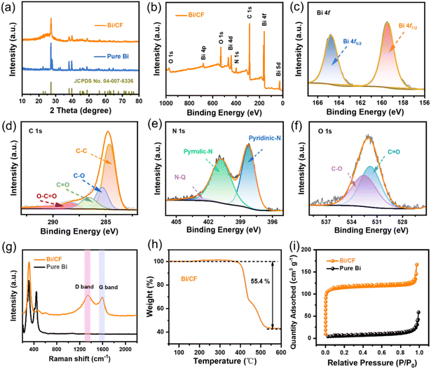
The structural characteristics of the prepared sample were first evaluated by XRD in Fig. 3(a). It can be shown that pure Bi and Bi/CF samples exhibit similar characteristic diffraction peaks which are located at 2θ = 22.6°, 23.8°, 27.2°, 38.1°, 39.7°, 48.8°, 62.4°, 64.7°, 71.0° and 72.1°, respectively. The characteristic peaks of both correspond to the standard PDF card (JCPDS No. 04-007-5336). It is worth noting that a broad peak at ca. 24° confirms the presence of amorphous carbon in Bi/CF. Meanwhile, the presence of weak peaks at 30.2° (−212) and 32.8° (130) indicates the presence of a small amount of bismuth oxide in Bi/CF electrode. Due to unavoidable oxidation during sample preparation, the XRD test results of the two samples showed the peaks of bismuth oxide. As shown in Fig. 3(b), X-ray photoelectron spectroscopy (XPS) measurements were employed to investigate the chemical state of the Bi/CF. The survey spectrum manifests that Bi/CF contains Bi, C, N and O elements. The oxygen content in Bi/CF results from the natural features of carbon fiber and the sample's exposure to air. The high-resolution Bi 4f signal of Bi/CF in Fig. 3(c) can mainly be fitted with two peaks located at 159.5 and 164.8 eV, which correspond to Bi 4f7/2 and Bi 4f5/2, respectively. In Fig. 3(d), the C 1s signal of Bi/CF can be fitted into a series of peaks located at 284.8, 285.4, 286.1 and 288.7 eV, corresponding to the C–C, C–O, O![[double bond, length as m-dash]](https://www.rsc.org/images/entities/char_e001.gif) C and O
C and O![[double bond, length as m-dash]](https://www.rsc.org/images/entities/char_e001.gif) O–C bonds, respectively. Fig. 3(e) shows that the spectrum of N 1s can be decomposed into three peaks, which are pyridinic-N (N-6, 398.1 eV), pyrrolic-N (N-5, 400.8 eV) and quaternary-N (N-Q, 401.6 eV). The existence of nitrogen heteroatoms comes from the decomposition of polyacrylonitrile calcination process. Meanwhile, the oxygen peaks at 531.8 and 532.5 eV in Fig. 3(f) are related to the C
O–C bonds, respectively. Fig. 3(e) shows that the spectrum of N 1s can be decomposed into three peaks, which are pyridinic-N (N-6, 398.1 eV), pyrrolic-N (N-5, 400.8 eV) and quaternary-N (N-Q, 401.6 eV). The existence of nitrogen heteroatoms comes from the decomposition of polyacrylonitrile calcination process. Meanwhile, the oxygen peaks at 531.8 and 532.5 eV in Fig. 3(f) are related to the C![[double bond, length as m-dash]](https://www.rsc.org/images/entities/char_e001.gif) O and C–O bonds.
O and C–O bonds.
Fig. 3(g) shows the Raman spectra of pure Bi and Bi/CF, and the characteristic peak located at 315 cm−1 is attributed to Bi nanocrystals. Meanwhile, two carbon peaks at around 1345 and 1593 cm−1 for Bi/CF are attributed to the D- and G-bands of carbon, respectively. The ratio of ID/IG is calculated to 1.12, indicating the presence of amorphous carbon. To investigate the mass proportion of Bi in the Bi/CF composite, TGA tests were carried out in Fig. 3(h). The thermogravimetric curve shows that the weight of samples starts to increase around 300 °C, which is due to the weight increase caused by oxidation. The subsequent reduction in total weight is mainly due to the weight loss caused by the oxidation of carbon fibers to carbon dioxide. The final reaction is completed at around 500 °C and the electrode composition is converted to Bi2O3. According to the law of conservation of energy, the weight percentage of bismuth in the Bi/CF electrode is estimated to be 49.7%. Furthermore, the N2 adsorption and desorption measurements were performed to identify the specific surface area of samples. In Fig. 3(i), the Bi/CF samples exhibit an IV type isotherm with an enlarged specific area of 156.2 m2 g−1. The increase in specific surface area (compared to pure bismuth with 48.7 m2 g−1) is mainly due to the extensive distribution of bismuth nanoparticles in carbon fibers, which leads to an increase in active sites.
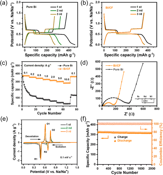
In order to investigate the sodium storage characteristics of the Bi/CF electrode, CR2032 sodium ion batteries were assembled in a glove box filled with high-purity argon gas for electrochemical testing. Fig. 4(a) exhibits the galvanostatic charge and discharge (GCD) curves of the pure Bi electrode for the first three cycles at a current density of 0.1 A g−1. The pure Bi electrode presents a relatively high initial discharge capacity, but rapidly decays in the second and third cycles. As shown in Fig. 4(b), it is obvious that the Bi/CF electrode represents a high reversible capacity of 376.6 mA h g−1 in the secondary cycles and there is no significant attenuation in the subsequent cycle. The sodium storage capability of the Bi particles in the composite is calculated by deducting the capacity contributions from the carbon fiber (∼300 mA h g−1). Fig. 4(c) shows the comparison of the rate performance between the pure Bi and Bi/CF electrode at the current densities range from 0.1 A g−1 to 10.0 A g−1. It is evident that the Bi/CF electrode delivers a higher discharge specific capacity than pure Bi which is 376.5, 356.8, 343.6, 329.2, 318.1, 302.3 and 283.9 mA h g−1 at the current densities of 0.1, 0.2, 0.5, 1.0, 2.0, 5.0 and 10.0 A g−1, respectively. With the continuous increase of current density, the capacity of pure Bi electrode rapidly decays, indicating that it does not have cyclic structural stability. As displayed in Fig. 4(d), the EIS measurement was carried out for analyzing the kinetic feature of the Bi/CF electrode with respect to sodium ions. The semicircle region stands for the charge transfer resistance (Rct), which is associated with the electrochemical kinetics of the electrodes. At the same time, the oblique line represents the Warburg impedance (Zw), which is decided by the sodium ion diffusion in the electrode. According to the equivalent circuit (inset diagram), the Rct of Bi/CF and pure Bi are computed to be 174.6 Ω and 389.6 Ω respectively. A smaller Rct value of Bi/CF implies lower charge transfer resistance and higher conductivity.
CV curve of Bi/CF electrode in the potential range of 0.01–1.5 V is performed at a scan rate of 0.1 mV s−1 in Fig. 4(e). Two cathodic peaks located at 0.48 V and 0.69 V can be observed, corresponding to the alloying reaction process from Bi to NaBi and Na3Bi. During the desodination, two oxidations at 0.61 V and 0.75 V are attributed to the transformation of Na3Bi phases to NaBi and de-alloying reaction of NaBi to Bi. The CV plot corresponds well with the GCD curve, which confirms the excellent stability of the Bi/CF electrode. Furthermore, the long-term cycling stability of the Bi/CF electrode for 2000 cycles is shown in Fig. 4(f). At high current density of 1.0 A g−1, the reversible capacity still maintained at 316.2 mA h g−1 with the CE over 99%, indicating the superior long-term cycle stability of Bi/CF electrode. Meanwhile, the SEM image of the Bi/CF electrode after 2000 cycles is shown in Fig. S5.† In order to verify the practicality of the flexible free-standing electrode, it was assembled into a flexible sodium ion battery with a thin strip shape. After connecting the two batteries in series, they can supply power to a smart bracelet (Fig. S6†). In addition, the comparison between the previous reported literature related to bismuth-based materials in sodium ion batteries (such as Bi-C/CF,14 Bi@C composite,15 Nano Bi@carbon nanofiber,16 3D porous Bi@3DGFs,17 Porous Bi/N-C,18 Bi@C microsphere19) in Table S1† confirms the superiority of Bi/CF electrode.
4. Conclusions
In summary, flexible and free-standing Bi/CF composite electrodes are successfully fabricated via a facile approach of electrospinning and calcination. Interwoven carbon fibers are beneficial for improving structural stability and can effectively mitigate the volume expansion effect of Bi/CF electrode during cycling process. Bismuth nanoparticles help to enhance effective active sites that can accelerate ion/electron transport. Benefiting from the excellent conductivity of carbon fibers and the synergistic effect of nanoscale bismuth particles, the electrode exhibits excellent sodium storage properties of rapid kinetic properties and long-term cycle life. This work gives a fresh guidance for improving the sodium storage performance of bismuth based electrodes.Data availability
All data used in this study were presented in the manuscript.Author contributions
Yang Cao: conceptualization, writing – original draft, preparation. Shiwei Wei: investigation, writing – reviewing and editing. Huifang Zhang: investigation, preparation, conceptualization. Yong Yan: investigation, reviewing. Zhiling Peng: conceptualization, investigation. Heming Zhao: supervision, resources.Conflicts of interest
There are no conflicts to declare.Acknowledgements
This work was financially supported by Local Science and Technology Development Fund project guided by the Central Government of China (YDZJSX2022A024, YDZJSX20231A026); Scientific and Technological Innovation Programs of Higher Education Institutions in Shanxi (2024L199); Shanxi Key Laboratory of High-end Equipment Reliability Technology (No. 446110103).Notes and references
- P. Du, X. M. Fan, B. Zhang, L. Cao, J. C. Ren, X. Ou, X. Y. Guo and Q. Liu, Energy Storage Mater., 2022, 50, 648–657 CrossRef.
- L. Sun, Y. X. Liu, R. Shao, J. Wu, R. Y. Jiang and Z. Jin, Energy Storage Mater., 2022, 46, 482–502 CrossRef.
- R. Xu, Z. L. Yi, M. X. Song, J. P. Chen, X. X. Wei, F. Y. Su, L. Q. Dai, G. H. Sun, F. Yang, L. J. Xie and C. M. Chen, Carbon, 2023, 206, 94–104 CrossRef CAS.
- H. Chen, N. Sun, Y. Wang, R. A. Soomro and B. Xu, Energy Storage Mater., 2023, 56, 532–541 CrossRef.
- Y. Lu, C. Zhao, X. Qi, Y. Qi, H. Li, X. Huang, L. Chen and Y. S. Hu, Adv. Energy Mater., 2018, 8, 1800108 CrossRef.
- C. Huang, A. Xu, G. Li, H. Sun, S. Wu, Z. Xu and Y. Yan, Small, 2021, 17, e2100685 CrossRef PubMed.
- Q. N. Liu, Z. Hu, M. Z. Chen, C. Zou, H. L. Jin, S. Wang, S. L. Chou, Y. Liu and S. X. Dou, Adv. Funct. Mater., 2020, 30, 1909530 CrossRef CAS.
- Q. Liu, Z. Hu, M. Chen, C. Zou, H. Jin, S. Wang, S. L. Chou and S. X. Dou, Small, 2019, 15, 1805381 CrossRef PubMed.
- M. K. Aslam and M. W. Xu, Nanoscale, 2020, 12, 15993–16007 RSC.
- Y. Wang, N. Xiao, Z. Wang, H. Li, M. Yu, Y. Tang, M. Hao, C. Liu, Y. Zhou and J. Qiu, Chem. Eng. J., 2018, 342, 52–60 CrossRef CAS.
- T. Liu, R. Yan, E. Josef, H. Huang, L. Pan, M. Niederberger and M. Oschatz, Electrochem. Sci. Adv., 2021, 1, e2100010 CrossRef CAS.
- X. Chen, Y. Xu, J. Tang, Y. Li, J. Hu, K. Zhang, S. Zhang and Y. Yao, J. Energy Storage, 2024, 99, 113395 CrossRef.
- H. Zhu, F. Wang, L. Peng, T. Qin, F. Kang and C. Yang, Angew Chem., Int. Ed. Engl., 2023, 62, e202212439 CrossRef CAS PubMed.
- Y. Zhang, Q. Su, W. Xu, G. Cao, Y. Wang, A. Pan and S. Liang, Adv. Sci., 2019, 6, 1900162 CrossRef PubMed.
- P. Xiong, P. Bai, A. Li, B. Li, M. Cheng, Y. Chen, S. Huang, Q. Jiang, X. H. Bu and Y. Xu, Adv. Mater., 2019, 31, 1904771 CrossRef CAS PubMed.
- H. Yin, Q. Li, M. Cao, W. Zhang, H. Zhao, C. Li, K. Huo and M. Zhu, Nano Res., 2017, 10, 2156–2167 CrossRef CAS.
- X. Cheng, D. Li, Y. Wu, R. Xu and Y. Yu, J. Mater. Chem. A, 2019, 7, 4913–4921 RSC.
- L. Wang, A. A. Voskanyan, K. Y. Chan, B. Qin and F. Li, ACS Appl. Energy Mater., 2019, 3, 565–572 CrossRef.
- F. Yang, F. Yu, Z. Zhang, K. Zhang, Y. Lai and J. Li, Chemistry, 2016, 22, 2333–2338 CrossRef CAS PubMed.
Footnote |
| † Electronic supplementary information (ESI) available. See DOI: https://doi.org/10.1039/d4ra07887j |
| This journal is © The Royal Society of Chemistry 2024 |


