 Open Access Article
Mesoporous Mo-doped PtBi intermetallic metallene superstructures to enable the complete electrooxidation of ethylene glycol†
Xiaotong
Yang
a,
Qiang
Yuan
 *a,
Tian
Sheng
 *c and
Xun
Wang
 *b
*b
aState-Local Joint Laboratory for Comprehensive Utilization of Biomass, Center for R&D of Fine Chemicals, College of Chemistry and Chemical Engineering, Guizhou University, Guiyang, Guizhou province 550025, P. R. China. E-mail: qyuan@gzu.edu.cn
bKey Lab of Organic Optoelectronics & Molecular Engineering, Tsinghua University, Beijing 100084, P. R. China. E-mail: wangxun@mail.tsinghua.edu.cn
cCollege of Chemistry and Materials Science, Anhui Normal University, Wuhu 241000, P. R. China. E-mail: TSheng@ahnu.edu.cn
First published on 12th February 2024
Abstract
Metallenes, intermetallic compounds, and porous nanocrystals are the three types of most promising advanced nanomaterials for practical fuel cell devices, but how to integrate the three structural features into a single nanocrystal remains a huge challenge. Herein, we report an efficient one-step method to construct freestanding mesoporous Mo-doped PtBi intermetallic metallene superstructures (denoted M-PtBiMo IMSs) as highly active and stable ethylene glycol oxidation reaction (EGOR) catalysts. The materials retained their catalytic performance, even in complex direct ethylene glycol fuel cells (DEGFCs). The M-PtBiMo IMSs showed EGOR mass and specific activities of 24.0 A mgPt−1 and 61.1 mA cm−2, respectively, which were both dramatically higher than those of benchmark Pt black and Pt/C. In situ infrared spectra showed that ethylene glycol underwent complete oxidation via a 10-electron CO-free pathway over the M-PtBiMo IMSs. Impressively, M-PtBiMo IMSs demonstrated a much higher power density (173.6 mW cm−2) and stability than Pt/C in DEGFCs. Density functional theory calculations revealed that oxophilic Mo species promoted the EGOR kinetics. This work provides new possibilities for designing advanced Pt-based nanomaterials to improve DEGFC performance.
Introduction
Platinum (Pt) group nanostructures play a central role in renewable energy devices such as fuel cells, hydrogen-generating electrolyzers, and metal–air batteries.1–5 However, their activity and stability depend closely on their micromorphology (e.g., dimensions, size, pore structure),6–9 crystal phase (e.g., amorphous/crystalline, polycrystalline/monocrystalline, or disordered/ordered),9–11 and surface content. Metallenes, intermetallics, and mesoporous metal nanocrystals are the three most promising electrocatalysts for energy-related industrial devices because of their intrinsic physicochemical properties. For example, their ultrathin two-dimensional (2D) structures give metallenes many accessible active sites due to the presence of unsaturated coordination atoms on their surface, high specific surface area, and high conductivity.12–16 Ordered intermetallics are more stable than random alloys because d–d orbital interactions between Pt and heteroatoms are stronger than those in random Pt-based nanoalloys. This also results in stronger electronic, ligand, and geometric effects.10,17,18 The mesoporous structure of metal nanostructures facilitates mass/electron transport and increases the number of accessible edge active sites.19–21 Because of these characteristics, metal nanocrystals have been used to boost the performance of electrocatalysis. Although great progress has been made in the preparation of metallenes, intermetallics, and mesoporous metal nanostructures, metal nanostructures that integrate these three structural features have not yet been reported.Herein, we constructed freestanding three-dimensional (3D) nanoflower-like mesoporous Mo-doped PtBi intermetallic metallene superstructures via a one-pot wet chemical method. A study of the synthesis mechanism revealed that the combined use of molybdenum hexacarbonyl (Mo(CO)6) and ammonium bromide (NH4Br) was essential to the M-PtBiMo IMSs. By integrating the advantages of the mesoporous structure and intermetallic metallene, M-PtBiMo IMSs exhibited excellent ethylene glycol oxidation reaction (EGOR) and practical direct ethylene glycol fuel cell (DEGFC) performance in alkaline media. They displayed a mass activity (MA) and specific activity (SA) of 24.0 A mgPt−1 and 61.1 mA cm−2, respectively, which were higher than those of Pt black (2.8 A mgPt−1/9.2 mA cm−2) and Pt/C (3.5 A mgPt−1/5.3 mA cm−2). Electrochemical in situ infrared spectroscopy showed that EG achieved 10-electron complete oxidation via a direct pathway on M-PtBiMo IMSs. Density functional theory (DFT) calculations revealed that oxophilic Mo species doped into PtBiMo formed more strongly-oxidizing MoO4 at low electrode potentials, which enhanced the EGOR kinetics. Even in a complex DEGFC, M-PtBiMo IMSs obtained a peak power density (PPD) of 173.6 mW cm−2, which was much higher than that of commercial Pt/C (100.7 mW cm−2). The cell voltage loss was also lower than that of Pt/C after a high constant current density of 400 mA cm−2 for 10 h, demonstrating the enormous potential of M-PtBiMo IMSs for practical DEGFC applications.
Results and discussion
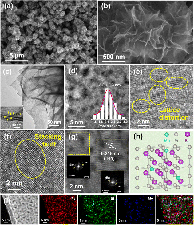
M-PtBiMo IMSs were obtained via a one-pot wet chemical method using platinum acetylacetonate (Pt(acac)2), Mo(CO)6, and bismuth nitrate pentahydrate (Bi(NO3)3·5H2O) as metal precursors. NH4Br was used as the structure directing agent, polyvinylpyrrolidone (PVP-K30) as the surfactant, and N, N-dimethylformamide (DMF) as the solvent at 150 °C for 8 h (details in the ESI†). Scanning electron microscopy (SEM), transmission electron microscopy (TEM), and high-angle annular dark-field scanning transmission electron microscopy (HAADF-STEM) images of M-PtBiMo IMSs revealed that they were assembled from ultrathin and wrinkled 2D interconnected nanosheets that formed a freestanding 3D nanoflower-like structure with a lateral size of 900 ± 50 nm (Fig. 1a, b and S1†). The nanosheets are highly curved and flexible (Fig. 1b, c and S1†), indicating their ultrathin nature, which allowed them to generate interwoven geometric shapes, local deformation strain, and provide more active sites.12,14,22 The thickness of the nanosheets is approximately 1.8 nm, as measured from the folded edge in the TEM images (Fig. 1c inset, Fig. S2†). In addition, abundant mesopores are observed in the HAADF-STEM image of M-PtBiMo IMSs (Fig. 1d), with the average mesopore size of 2.2 ± 0.3 nm (Fig. 1d inset), which favored mass and electron transfer and also provided unsaturated atoms and a high specific surface area, all of which should enhance their electrocatalytic properties.23,24 Some lattice distortions (Fig. 1e) and stacking faults (Fig. 1f) are also observed, which provided many active sites and improved the electrocatalytic activity.25–27 The high-resolution HAADF-STEM image (Fig. 1g) illustrates that the lattice spacing is 0.215 nm, which corresponded to the (110) lattice spacing of intermetallic PtBi. The Fast Fourier-Transform (FFT) patterns (Fig. 1g inset) further indicate the existence of a hexagonal phase.28,29Fig. 1h shows a schematic of the crystal structure of the M-PtBiMo IMSs. The HAADF-STEM images and corresponding element mappings (Fig. 1i and S3†) show that Pt, Bi, and Mo atoms are dispersed throughout the M-PtBiMo IMSs (Fig. 1i and S3†), in which Mo is adjacent to Pt (Fig. S4†). The Pt![[thin space (1/6-em)]](https://www.rsc.org/images/entities/char_2009.gif) :
:![[thin space (1/6-em)]](https://www.rsc.org/images/entities/char_2009.gif) Bi
Bi![[thin space (1/6-em)]](https://www.rsc.org/images/entities/char_2009.gif) :
:![[thin space (1/6-em)]](https://www.rsc.org/images/entities/char_2009.gif) Mo ratio of M-PtBiMo IMSs was determined by inductively coupled plasma-optical emission spectrometry (ICP-OES) to be 60.2
Mo ratio of M-PtBiMo IMSs was determined by inductively coupled plasma-optical emission spectrometry (ICP-OES) to be 60.2![[thin space (1/6-em)]](https://www.rsc.org/images/entities/char_2009.gif) :
:![[thin space (1/6-em)]](https://www.rsc.org/images/entities/char_2009.gif) 36.6
36.6![[thin space (1/6-em)]](https://www.rsc.org/images/entities/char_2009.gif) :
:![[thin space (1/6-em)]](https://www.rsc.org/images/entities/char_2009.gif) 3.2.
3.2.
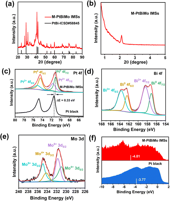
The X-ray diffraction (XRD) pattern indicates the high crystallinity of M-PtBiMo IMSs (Fig. 2a), with diffraction peaks corresponding to the intermetallic PtBi phase (ICSD#58845) with a hexagonal close-packed (hcp) structure.29–31 The small-angle XRD pattern (Fig. 2b) further confirms the formation of mesoporous structures. X-ray photoelectron spectroscopy (XPS) shows that metallic and oxidized Pt and Bi and fully-oxidized Mo (MoOx) coexist in the near-surface region of M-PtBiMo IMSs. Fig. 2c shows that the metallic Pt 4f7/2 of M-PtBiMo IMSs (71.07 eV) shifts negatively by 0.33 eV compared with that of Pt black (71.40 eV). The metallic Bi 4f7/2 core level of M-PtBiMo IMSs is located at a higher binding energy (157.11 eV) than that of metallic Bi (157 eV) (Fig. 2d). The opposite shift in the metallic Pt 4f and Bi 4f core levels indicates strong interactions between Pt and Bi atoms, and charge transfer from Bi to Pt occurred.31 In the Mo 3d spectrum in Fig. 2e, the peaks at binding energies of 231.05 eV, 234.15 eV, 231.76 eV, and 234.87 eV are assigned to Mo4+ 3d5/2, Mo4+ 3d3/2, Mo5+ 3d5/2, and Mo5+ 3d3/2, respectively. These peaks indicate that outer Mo atoms were oxidized to MoOx species during the reaction, which facilitated water dissociation and generated abundant oxygen-containing species (OHads) that promoted electrocatalytic reactions.32,33 Additionally, the valence band spectrum (Fig. 2f) revealed that the d-band center of M-PtBiMo IMSs (−4.81 eV) shifted downwards compared with that of pure Pt (−3.77 eV). This weakened the binding strength between Pt and intermediates, accelerated the reaction kinetics, and improved the catalytic performance.30,34
We explored the effect of different experimental parameters on the growth mechanism of M-PtBiMo IMSs through a series of comparative experiments. During synthesis, using an appropriate molar ratio of Mo(CO)6/NH4Br is crucial to ensure the growth of M-PtBiMo IMSs (Fig. S5 and S6†). In the absence of Mo(CO)6, Pt68.5Bi31.5 nanoparticles (Fig. S5a†) were formed, as confirmed by ICP-OES (denoted PtBi NPs), while in the absence of NH4Br, nanochains (Fig. S6a†) were formed. Mo(CO)6 thermally decomposed to generate Mo and CO during synthesis, and the generated CO attached to the surface of metal atoms,35,36 thus inducing the directed formation of defect-rich M-PtBiMo IMSs. Due to this, we utilized W(CO)6, Cr(CO)6, Ru(CO)12, and Co2(CO)8 instead of Mo(CO)6, which also produced CO during synthesis. When equal amounts of W(CO)6, Cr(CO)6, Ru(CO)12, and Co2(CO)8 were used, irregular nanoparticles (Fig. S7a†), large plate-like structures (Fig. S7b†), dendrite-like structures (Fig. S7c†), and agglomerated irregular lamellar structures (Fig. S7d†) were obtained, respectively. These results indicated that M-PtBiMo IMSs could not form in the absence of Mo(CO)6. We also found that NH4Br played a pivotal role in inducing the growth of M-PtBiMo IMSs. When NH4F was employed instead of NH4Br, bulk irregular nanocrystals were obtained (Fig. S8a†). When an equal amount of NH4Cl was used instead of NH4Br, 2D assembled sheets were formed, but they were thicker (Fig. S8b†). Replacing NH4Br with NH4I yielded unevenly-sized hexagonal nanosheets (Fig. S8c†), possibly because Br− could be complexed with metal ions, which changed the reduction potentials of different metal atoms and the reduction kinetics.37 This also avoided the random nucleation of metal atoms during synthesis and favored the selective growth of M-PtBiMo IMSs. The above control experiments indicated that Mo(CO)6 and NH4Br played crucial roles in obtaining the target products, M-PtBiMo IMSs.
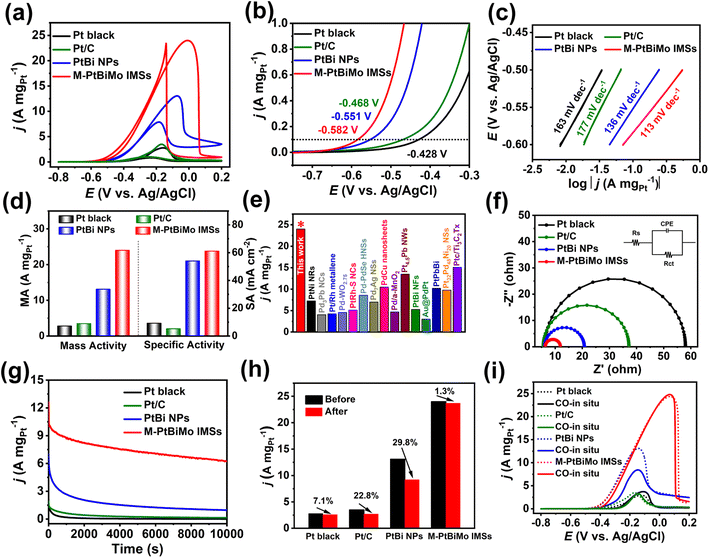
The EGOR was selected to comparatively evaluate the catalytic performance of M-PtBiMo IMSs with Pt black (Fig. S9a†), Pt/C (Fig. S9b†), and PtBi NPs (Fig. S5a†) as references. The cyclic voltammograms (CVs) of all catalyst samples were recorded in 1 M KOH solution at room temperature, as shown in Fig. S10.† Compared with Pt black and Pt/C catalysts, no hydrogen adsorption/desorption peak was observed for PtBi NP and M-PtBiMo IMS catalysts because bismuth inhibited hydrogen adsorption on the Pt.29,31,37 The electrochemically active surface areas (ECSA) of M-PtBiMo IMSs, PtBi NPs, Pt black, and Pt/C were determined by the desorption peaks of CO stripping (Fig. S11†) and were calculated to be 39.3 m2 gPt−1, 24.2 m2 gPt−1, 30.4 m2 gPt−1, and 66.2 m2 gPt−1, respectively. Fig. 3a shows the EGOR CV curves recorded in 1 M KOH + 1 M EG electrolyte to investigate the electrocatalytic activities. The onset potential (the MA of 0.1 A mgPt−1) of M-PtBiMo IMSs (−0.582 V) was 154 mV, 114 mV, and 31 mV more negative than those of commercial Pt black (−0.428 V), Pt/C (−0.468 V), and PtBi NPs (−0.551 V), respectively, indicating a lower activation barrier during EG oxidation (Fig. 3b).38,39 In addition, M-PtBiMo IMSs exhibited the lowest Tafel slope (113 mV dec−1), indicating the fastest kinetics during the EGOR (Fig. 3c). Notably, the M-PtBiMo IMSs exhibited the highest peak MA/SA of 24.0 A mgPt−1/61.1 mA cm−2, which were 8.6/6.6, 6.9/11.5, and 1.8/1.1 times higher than those of Pt black, Pt/C, and PtBi NPs, respectively (Fig. 3d). The MA of M-PtBiMo IMSs was also superior to most advanced EGOR electrocatalysts (Fig. 3e and Table S1†). For example, the MA of M-PtBiMo IMSs is 2.3, 4.5, 5.6, and 7.9 times those of PtPbBi hexagonal nanoplates,40 PtBi nanoflowers,41 Pt/Rh metallene,42 and Au@PdPt,43 respectively. Electrochemical impedance spectroscopy (EIS) was performed to assess the electron transfer rates of these electrocatalysts during the EGOR. According to the equivalent circuit used to fit the Nyquist plot (Fig. 3f), the charge-transfer resistance (Rct) of the M-PtBiMo IMSs was smaller than that of PtBi NPs, Pt black, and Pt/C electrocatalysts, implying rapid charge-transfer and they provided improved catalytic performance.44 These results once again indicate the superior performance of the M-PtBiMo IMS electrocatalyst during the EGOR.
The electrocatalytic stability of M-PtBiMo IMSs was also investigated by the I–t measurement at a working potential of −0.25 V (vs. Ag/AgCl) (Fig. 3g). The M-PtBiMo IMSs had the best durability from the I–t measurements, with a retained MA of 6.2 A mgPt−1 at 10![[thin space (1/6-em)]](https://www.rsc.org/images/entities/char_2009.gif) 000 s, which was 6.5, 44.3, and 620 times higher than those of PtBi NPs, Pt/C, and Pt black catalysts, respectively. Furthermore, Fig. 3h and S12† demonstrate that the M-PtBiMo IMSs exhibited negligible attenuation in their catalytic activity after 10
000 s, which was 6.5, 44.3, and 620 times higher than those of PtBi NPs, Pt/C, and Pt black catalysts, respectively. Furthermore, Fig. 3h and S12† demonstrate that the M-PtBiMo IMSs exhibited negligible attenuation in their catalytic activity after 10![[thin space (1/6-em)]](https://www.rsc.org/images/entities/char_2009.gif) 000 s of the I–t test. The superior tolerance of these catalysts was revealed by in situ CO experiments (Fig. 3i). When CO was input during EGOR performance tests, the EGOR performance of M-PtBiMo IMSs was unaffected, confirming its resistance to CO poisoning. The enhanced CO tolerance was derived from the downshift of the d-band center of M-PtBiMo IMSs, which weakened CO adsorption.30 Simultaneously, based on a dual-function mechanism, the introduction of oxophilic metals Bi and Mo promoted the production of reactive oxygen species around Pt active sites and also promoted the removal of adsorbed CO.33,45 The above results show that the superior EGOR stability of M-PtBiMo IMSs was due to the strong anti-CO poisoning capacity.
000 s of the I–t test. The superior tolerance of these catalysts was revealed by in situ CO experiments (Fig. 3i). When CO was input during EGOR performance tests, the EGOR performance of M-PtBiMo IMSs was unaffected, confirming its resistance to CO poisoning. The enhanced CO tolerance was derived from the downshift of the d-band center of M-PtBiMo IMSs, which weakened CO adsorption.30 Simultaneously, based on a dual-function mechanism, the introduction of oxophilic metals Bi and Mo promoted the production of reactive oxygen species around Pt active sites and also promoted the removal of adsorbed CO.33,45 The above results show that the superior EGOR stability of M-PtBiMo IMSs was due to the strong anti-CO poisoning capacity.
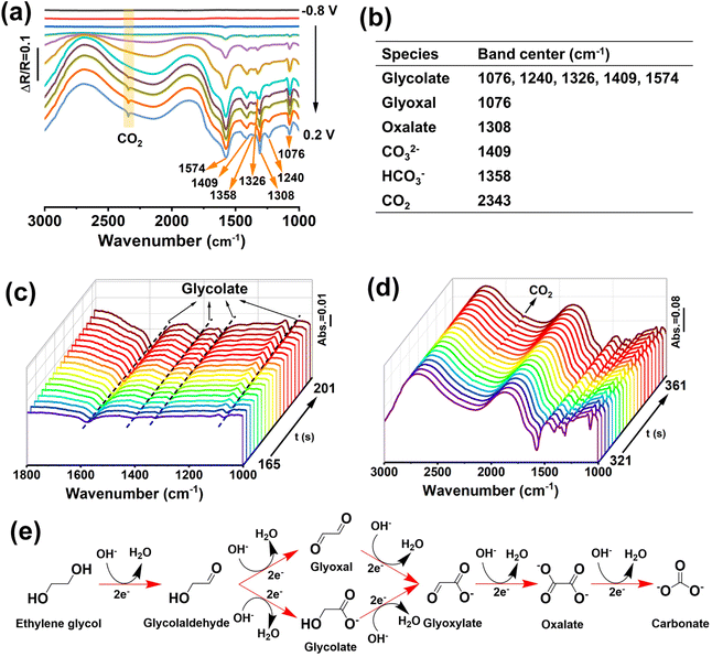
To further investigate the EGOR mechanism and reaction pathway, operando electrochemical in situ FTIR measurements of M-PtBiMo IMSs were conducted, as shown in Fig. 4a, and the characteristic IR bands are summarized in Fig. 4b. The EG molecules were activated at a low potential and exhibited distinct vibrational bands. The band at 1076 cm−1 belonged to the stretching vibration of aldehyde from glyoxal and glycolate substances.30,46 The bands at 1076, 1240, 1326, 1409, and 1574 cm−1 indicated the formation of glycolate (Fig. 4a and c), and the band at 1308 cm−1 was ascribed to oxalate.29,47,48 The strong band at 2343 cm−1 indicated CO2 formation (Fig. 4d) at −0.1 V. The bands at 1408 cm−1 and 1358 cm−1 were attributed to the characteristic vibration bands of carbonate (CO32−) and bicarbonate (HCO3−). The presence of these C1 species (CO2, CO32−, and HCO3−) indicated that M-PtBiMo IMSs cleaved C–C bonds to achieve the desired 10-electron complete oxidation of EG while providing a higher energy conversion efficiency (CH2OH–CH2OH + 14OH− → 2CO32− + 10H2O + 10e−).49,50 Notably, no COad signal was detected for M-PtBiMo IMSs, indicating that a CO-free direct pathway was realized. The proposed mechanism of the complete electrooxidation of ethylene glycol on M-PtBiMo IMSs in alkaline media is illustrated in Fig. 4e.
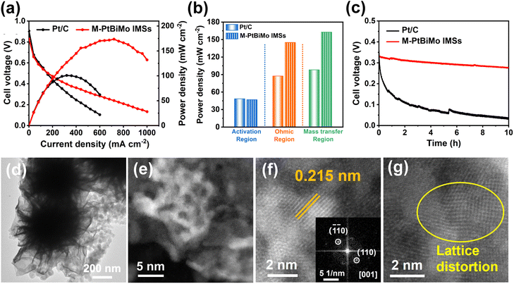
We were inspired by the EGOR kinetics, CO toxicity resistance, high activity, and stability of the M-PtBiMo IMS catalyst to evaluate its MEA performance (Fig. S13†) as a single DEGFC anode catalyst. We used commercial Pt/C as a benchmark anode catalyst for MEA testing. The DEGFC of M-PtBiMo IMSs delivered a current density of 720 mA cm−2 at 0.24 V and achieved a PPD of 173.6 mW cm−2 (Fig. 5a), which were 2.25 and 1.72 times higher than those of Pt/C (320 mA cm−2, 100.7 mW cm−2), respectively. The excellent PPD of M-PtBiMo IMSs is also better than recently published values (Table S2†). Compared with Pt/C, M-PtBiMo IMSs exhibited superior electron and mass transfer ability due to their 3D and mesoporous structures (Fig. 5b). Apart from the power density of the DEGFC, a catalyst's durability is also important to consider. Fig. 5c shows the durability of M-PtBiMo IMSs and Pt/C via a high constant current density at 400 mA cm−2 for 10 h. The result showed that commercial Pt/C exhibited a voltage decay as high as 70.3%, while M-PtBiMo IMSs exhibited only 12.5%, indicating the remarkable PPD and durability of M-PtBiMo IMSs for MEA. Furthermore, TEM (Fig. 5d and S14†) and high-resolution HAADF-STEM images (Fig. 5e–g) demonstrated that M-PtBiMo IMSs maintained their original morphology after long-term measurements under highly corrosive conditions. And the element diagrams (Fig. S15†) further proved the existence of Pt, Bi, and Mo. However, severe aggregation of Pt nanoparticles was observed in the Pt/C catalyst (Fig. S16†). The above results confirmed that the M-PtBiMo IMSs possessed significant electrochemical and structural stability because the 3D nanoflower morphology with lower surface total free energy greatly reduced agglomeration and Ostwald ripening.
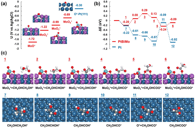
The surface oxophilic Mo species in Pt-based electrocatalysts promoted water activation, thus generating more reactive oxygen species and promoting electrocatalysis.51,52 We performed DFT calculations to reveal the origin of the enhanced electrooxidation of EG on PtBiMo. As depicted in Fig. 6a, at a potential of −1.72 V (vs. Ag/AgCl), one O atom is attached to the top site of Mo, resulting in the formation of a Mo–O bond with a length of 1.71 Å. As the potential was increased to −1.22 V and −0.99 V, more O atoms adsorbed onto the Mo atom to form MoO2 with a bond length of 1.76 Å and MoO3, respectively. Within the MoO3 group, the Mo atom connected to a surface Pt atom with a Pt–Mo bond length of 2.58 Å. Two O atoms bonded to the Pt and Bi atoms, while the remaining O atom was oriented upwards. Furthermore, at a potential of −0.69 V, the newly formed MoO4 species lifted off from the surface, leaving a vacancy (Fig. S17†). MoO4 exhibited tetrahedral coordination, with two O atoms bonded to two anchoring surface Bi atoms with a bond length of 1.84 Å; one O atom was bonded to a surface Pt atom and the other O atom was oriented upwards with a bond length of 1.73 Å. A similar MoO4 structure was also identified for PtNiMo catalysts, which also showed that MoO4 species enhanced electrocatalysis.53 Notably, the presence of Mo in PtBiMo provided a greater affinity for oxygen than pure Pt, allowing oxygen species to adsorb even at very low electrode potentials (Fig. S18†).
Next, we calculated the electro-oxidation mechanism of ethylene glycol, and a comparison of the reaction energies on PtBiMo and Pt is shown in Fig. 6b. The theoretical potential was set at −0.69 V, which matches the onset potential for the formation of MoO4 and closely approximates the experimental onset potential for ethylene glycol electrooxidation. The dehydrogenation pathway of ethylene glycol on PtBiMo (1 → 4) and Pt (7 → 10) followed the same steps (Fig. S19–S21†): CH2OHCH2OH* → CH2OHCHOH* → CH2OHCOH* → CH2OHCO*. The Pt surface exhibited greater activity for C–H bond activation. Subsequently, the O atom of MoO4 bonded to a surface Pt atom and attacked the C atom in the C![[double bond, length as m-dash]](https://www.rsc.org/images/entities/char_e001.gif) O bond (Fig. 6c). This initiated the formation of a C–O bond to produce glycolate with a reaction energy of −0.37 eV (4 → 5), thus confirming the oxidizing capability of MoO4. However, on Pt, O adsorption required an energy input of 0.78 eV (10 → 11), which explains the limited activity observed at lower electrode potentials.
O bond (Fig. 6c). This initiated the formation of a C–O bond to produce glycolate with a reaction energy of −0.37 eV (4 → 5), thus confirming the oxidizing capability of MoO4. However, on Pt, O adsorption required an energy input of 0.78 eV (10 → 11), which explains the limited activity observed at lower electrode potentials.
Conclusion
In conclusion, we obtained novel freestanding 3D nanoflower-like M-PtBiMo IMSs via a simple and effective one-step wet chemical synthesis method. Due to the integrated functions of the mesoporous structure, abundant defects, and strong electronic/synergistic effects, M-PtBiMo IMSs achieved complete ethylene glycol oxidation and significant EGOR activity and stability. Furthermore, when used as anode electrocatalysts in a practical DEGFC, M-PtBiMo IMSs displayed a higher PPD and superior stability that greatly exceeded those of commercial Pt/C. DFT calculations revealed that the enhanced catalytic performance may have been derived from the formation of more-oxidizing MoO4 by doping oxophilic Mo species in PtBiMo at low electrode potentials. This work adds a new member to the family of metal nanostructures and provides new ideas for the construction of superior Pt-based electrocatalysts for practical DEGFCs.Author contributions
The manuscript was written through contributions of all authors.Conflicts of interest
The authors declare no competing financial interest.Acknowledgements
This work was supported by the National Natural Science Foundation of China (21571038, 201903001, 22035004), Education Department of Guizhou Province (2021312) and Foundation of Guizhou Province (2019-5666), Natural Science Foundation of Anhui Province (1908085QB58) and the Open Fund of the Key Lab of Organic Optoelectronics & Molecular Engineering (Tsinghua University). We gratefully acknowledge the computing resources provided by the College of Chemistry and Materials Science of Anhui Normal University.Notes and references
- K. Kodama, T. Nagai, A. Kuwaki, R. Jinnouchi and Y. Morimoto, Nat. Nanotechnol., 2021, 16, 140–147 CrossRef CAS PubMed.
- L. Huang, S. Zaman, X. L. Tian, Z. T. Wang, W. S. Fang and B. Y. Xia, Acc. Chem. Res., 2021, 54, 311–322 CrossRef CAS PubMed.
- F. Xiao, Q. Wang, G. L. Xu, X. P. Qin, I. H. Hwang, C. J. Sun, M. Liu, W. Hua, H. W. Wu, S. Q. Zhu, J. C. Li, J. G. Wang, Y. M. Zhu, D. J. Wu, Z. D. Wei, M. Gu, K. Amine and M. H. Shao, Nat. Catal., 2022, 5, 503–512 CrossRef CAS.
- G. L. Gao, G. Zhu, X. L. Chen, Z. X. Sun and A. Cabot, ACS Nano, 2023, 17, 20804–20824 CrossRef PubMed.
- L. B. Li, X. N. Tang, B. Wu, B. Y. Huang, K. Yuan and Y. W. Chen, Adv. Mater., 2023, e2308326 Search PubMed.
- C. Perego and R. Millini, Chem. Soc. Rev., 2013, 42, 3956–3976 RSC.
- S. Dutta, B. S. Gu and I. S. Lee, Angew. Chem., Int. Ed., 2023, 62, e202312656 CrossRef CAS PubMed.
- D. Alloyeau, C. Ricolleau, C. Mottet, T. Oikawa, C. Langlois, Y. Le Bouar, N. Braidy and A. Loiseau, Nat. Mater., 2009, 8, 940–946 CrossRef CAS PubMed.
- Y. M. He, L. R. Liu, C. Zhu, S. S. Guo, P. Golani, B. Koo, P. Y. Tang, Z. Q. Zhao, M. Z. Xu, P. Yu, X. Zhou, C. T. Gao, X. W. Wang, Z. D. Shi, L. Zheng, J. F. Yang, B. Shin, J. Arbiol, H. G. Duan, Y. H. Du, M. Heggen, R. E. Dunin-Borkowski, W. L. Guo, Q. J. Wang, Z. H. Zhang and Z. Liu, Nat. Catal., 2022, 5, 212–221 CrossRef CAS.
- Y. Chen, Z. Lai, X. Zhang, Z. Fan, Q. He, C. Tan and H. Zhang, Nat. Rev. Chem, 2020, 4, 243–256 CrossRef CAS PubMed.
- M. Zhou, C. Li and J. Y. Fang, Chem. Rev., 2021, 121, 736–795 CrossRef CAS PubMed.
- M. H. Xie, S. S. Tang, B. W. Zhang and G. H. Yu, Mater. Horiz., 2023, 10, 407–431 RSC.
- C. S. Cao, Q. Xu and Q.-L. Zhu, Chem Catal., 2022, 2, 693–723 CrossRef CAS.
- M. C. Luo, Z. L. Zhao, Y. L. Zhang, Y. J. Sun, Y. Xing, F. Lv, Y. Yang, X. Zhang, S. Hwang, Y. N. Qin, J. Y. Ma, F. Lin, D. Su, G. Lu and S. J. Guo, Nature, 2019, 574, 81–85 CrossRef CAS PubMed.
- Y. N. Qin, H. Huang, W. Yu, H. N. Zhang, Z. J. Li, Z. C. Wang, J. P. Lai, L. Wang and S. H. Feng, Adv. Sci., 2022, 9, 2103722 CrossRef CAS PubMed.
- Q. Q. Mao, X. Mu, K. Deng, H. J. Yu, Z. Q. Wang, Y. Xu, X. N. Li, L. Wang and H. J. Wang, Adv. Funct. Mater., 2023, 33, 2304963 CrossRef CAS.
- F. X. Lin, M. G. Li, L. Y. Zeng, M. C. Luo and S. J. Guo, Chem. Rev., 2023, 123, 12507–12593 CrossRef CAS PubMed.
- T. Y. Yoo, J. M. Yoo, A. K. Sinha, M. S. Bootharaju, E. Jung, H. S. Lee, B. H. Lee, J. Kim, W. H. Antink, Y. M. Kim, J. Lee, E. Lee, D. W. Lee, S. P. Cho, S. J. Yoo, Y. E. Sung and T. Hyeon, J. Am. Chem. Soc., 2020, 142, 14190–14200 CrossRef CAS PubMed.
- H. Lv, Y. Z. Wang, L. Z. Sun, Y. Yamauchi and B. Liu, Nat. Protoc., 2023, 18, 3126–3154 CrossRef CAS PubMed.
- H. Lv and B. Liu, Chem. Sci., 2023, 14, 13313–13324 RSC.
- N. Linares, A. M. Silvestre-Albero, E. Serrano, J. Silvestre-Albero and J. Garcia-Martinez, Chem. Soc. Rev., 2014, 43, 7681–7717 RSC.
- W. J. Tian, X. Zhang, Z. Q. Wang, L. Cui, M. Li, Y. Xu, X. N. Li, L. Wang and H. J. Wang, Chem. Eng. J., 2022, 440, 135848 CrossRef CAS.
- W. D. Ao, H. J. Ren, C. G. Cheng, Z. S. Fan, P. Q. Yin, Q. Qin, Q. Zhang and L. Dai, Angew. Chem., Int. Ed., 2023, 62, e202305158 CrossRef CAS PubMed.
- H. Jin, Z. W. Xu, Z. Y. Hu, Z. W. Yin, Z. Wang, Z. Deng, P. Wei, S. H. Feng, S. H. Dong, J. F. Liu, S. C. Luo, Z. D. Qiu, L. Zhou, L. Q. Mai, B. L. Su, D. Y. Zhao and Y. Liu, Nat. Commun., 2023, 14, 1518 CrossRef CAS PubMed.
- F. L. Zhao, S. Y. Nie, L. Wu, Q. Yuan and X. Wang, Adv. Mater., 2023, 35, e2303672 CrossRef PubMed.
- J. W.-J. Kang, Y. Feng, Z. Li, Z.-N. Chen, C.-K. Dong, J. Yang, P.-F. Yin, H. Liu and X.-W. Du, ACS Energy Lett., 2023, 8, 3512–3519 CrossRef.
- L. G. Li, S. H. Liu, C. H. Zhan, Y. Wen, Z. F. Sun, J. J. Han, T.-S. Chan, Q. B. Zhang, Z. W. Hu and X. Q. Huang, Energy Environ. Sci., 2023, 16, 157–166 RSC.
- X. L. Ji, K. T. Lee, R. Holden, L. Zhang, J. J. Zhang, G. A. Botton, M. Couillard and L. F. Nazar, Nat. Chem., 2010, 2, 286–293 CrossRef CAS PubMed.
- B. W. Zhang, W. H. Lai, T. Sheng, X. M. Qu, Y. X. Wang, L. Ren, L. Zhang, Y. Du, Y. X. Jiang, S. G. Sun and S. X. Dou, J. Mater. Chem. A, 2019, 7, 5214–5220 RSC.
- X. T. Yang, K. X. Yao, J. Y. Ye, Q. Yuan, F. L. Zhao, Y. F. Li and Z. Y. Zhou, Adv. Funct. Mater., 2021, 31, 2103671 CrossRef CAS.
- T. Wan, X. Huang, S. Li, Q. Li, X. Yang, Z. Sun, D. Xiang, K. Wang, P. Li and M. Zhu, Nano Res., 2023, 16, 6560–6567 CrossRef CAS.
- J. D. Wu, J. C. Fan, X. Zhao, Y. Wang, D. W. Wang, H. T. Liu, L. Gu, Q. H. Zhang, L. R. Zheng, D. J. Singh, X. Q. Cui and W. T. Zheng, Angew. Chem., Int. Ed., 2022, 61, e202207512 CrossRef CAS PubMed.
- H. Luo, K. Wang, F. X. Lin, F. Lv, J. H. Zhou, W. Y. Zhang, D. W. Wang, W. S. Zhang, Q. H. Zhang, L. Gu, M. C. Luo and S. J. Guo, Adv. Mater., 2023, 35, e2211854 CrossRef PubMed.
- X. L. Li, Y. Q. Huang, Z. Y. Chen, S. Q. Hu, J. L. Zhu, P. Tsiakaras and P. K. Shen, Chem. Eng. J., 2023, 454, 140131 CrossRef CAS.
- J. T. Zhang, X. Z. Liu, Y. J. Ji, X. R. Liu, D. Su, Z. B. Zhuang, Y. C. Chang, C. W. Pao, Q. Shao, Z. W. Hu and X. Q. Huang, Nat. Commun., 2023, 14, 1761 CrossRef CAS PubMed.
- E. Hornberger, M. Klingenhof, S. Polani, P. Paciok, A. Kormanyos, R. Chattot, K. E. MacArthur, X. Wang, L. Pan, J. Drnec, S. Cherevko, M. Heggen, R. E. Dunin-Borkowski and P. Strasser, Chem. Sci., 2022, 13, 9295–9304 RSC.
- Y. N. Qin, M. C. Luo, Y. J. Sun, C. J. Li, B. L. Huang, Y. Yang, Y. J. Li, L. Wang and S. J. Guo, ACS Catal., 2018, 8, 5581–5590 CrossRef CAS.
- H. D. Li, Y. Han, H. Zhao, W. J. Qi, D. Zhang, Y. D. Yu, W. W. Cai, S. X. Li, J. P. Lai, B. L. Huang and L. Wang, Nat. Commun., 2020, 11, 5437 CrossRef CAS PubMed.
- Y. Guo, X. B. Yang, X. C. Liu, X. L. Tong and N. J. Yang, Adv. Funct. Mater., 2022, 33, 2209134 CrossRef.
- Z. Zhu, F. Liu, J. Fan, Q. Li, Y. Min and Q. Xu, ACS Appl. Mater. Interfaces, 2020, 12, 52731–52740 CrossRef CAS PubMed.
- Y. P. Zhang, F. Gao, P. P. Song, J. Wang, T. X. Song, C. Wang, C. Q. Wang, J. Guo and Y. K. Du, J. Alloys Compd., 2019, 789, 834–840 CrossRef CAS.
- H. Wang, Y. Liang, S. Liu, H. Yu, K. Deng, Y. Xu, X. Li, Z. Wang and L. Wang, Inorg. Chem., 2023, 62, 14477–14483 CrossRef CAS PubMed.
- X. Yang, Q. Wang, S. Qing, Z. Gao, X. Tong and N. Yang, Adv. Energy Mater., 2021, 11, 2100812 CrossRef CAS.
- K. W. Zhang, C. Wang, H. M. You, B. Zou, S. Y. Guo, S. J. Li and Y. K. Du, Chem. Eng. J., 2022, 438, 135666 CrossRef CAS.
- X. C. Wang, M. Xie, F. L. Lyu, Y. M. Yiu, Z. Q. Wang, J. T. Chen, L. Y. Chang, Y. J. Xia, Q. X. Zhong, M. Y. Chu, H. Yang, T. Cheng, T. K. Sham and Q. Zhang, Nano Lett., 2020, 20, 7751–7759 CrossRef CAS PubMed.
- J.-X. Tang, Q.-S. Chen, L.-X. You, H.-G. Liao, S.-G. Sun, S.-G. Zhou, Z.-N. Xu, Y.-M. Chen and G.-C. Guo, J. Mater. Chem. A, 2018, 6, 2327–2336 RSC.
- S.-C. Chang, Y. Ho and M. J. Weaver, J. Am. Chem. Soc., 1991, 113, 9506–9513 CrossRef CAS.
- J. S. Li, L. M. Li, X. Y. Ma, X. Han, C. C. Xing, Q. Qi, R. He, J. Arbiol, H. Y. Pan, J. Zhao, J. Deng, Y. Zhang, Y. Y. Yang and A. Cabot, Adv. Sci., 2023, 10, e2300841 CrossRef PubMed.
- X. T. Yang, Q. Yuan, J. W. Li, T. Sheng, K. X. Yao and X. Wang, Nano Lett., 2023, 23, 3467–3475 CrossRef CAS PubMed.
- F. L. Zhao and Q. Yuan, Inorg. Chem., 2023, 62, 14815–14822 CrossRef CAS PubMed.
- J. J. Mao, W. X. Chen, D. S. He, J. W. Wan, J. J. Pei, J. C. Dong, Y. Wang, P. F. An, Z. Jin, W. Xing, H. L. Tang, Z. B. Zhuang, X. Liang, Y. Huang, G. Zhou, L. Y. Wang, D. S. Wang and Y. D. Li, Sci. Adv., 2017, 3, e1603068 CrossRef PubMed.
- M. G. Li, Z. L. Zhao, W. Y. Zhang, M. C. Luo, L. Tao, Y. J. Sun, Z. H. Xia, Y. G. Chao, K. Yin, Q. H. Zhang, L. Gu, W. W. Yang, Y. S. Yu, G. Lu and S. J. Guo, Adv. Mater., 2021, 33, e2103762 CrossRef PubMed.
- J. L. Li, Y. F. Li and Z. P. Liu, JACS Au, 2023, 3, 1162–1175 CrossRef CAS PubMed.
Footnote |
| † Electronic supplementary information (ESI) available: Experimental section; charaterizations (TEM, HAADF-STEM, elemental mappings), computational methods, CV curves, EIS, DFT calculations, and tables. See DOI: https://doi.org/10.1039/d4sc00323c |
| This journal is © The Royal Society of Chemistry 2024 |

