
 Open Access Article
 This Open Access Article is licensed under a Creative Commons Attribution-Non Commercial 3.0 Unported Licence
Electrocatalytic conversion of biomass-derived furan compounds: mechanisms, catalysts and perspectives
Peipei
Zhu
*,
Mingzhu
Shi
,
Zhipeng
Shen
,
Xunfan
Liao
 and
Yiwang
Chen
*
and
Yiwang
Chen
*
Key Laboratory of Fluorine and Silicon for Energy Materials and Chemistry of Ministry of Education, College of Chemistry and Chemical Engineering, Jiangxi Normal University, 99 Ziyang Avenue, Nanchang 330022, China. E-mail: ppzhu@jxnu.edu.cn; ywchen@ncu.edu.cn
First published on 27th February 2024
Abstract
Renewable biomass, with its abundant resources, provides a viable solution to address the energy crisis and mitigate environmental pollution. Furan compounds, including 5-hydroxymethylfurfural (HMF) and furfural (FF), serve as versatile platform molecules derived from the degradation of lignocellulosic cellulose, offering a crucial pathway for the conversion of renewable biomass. The electrocatalytic conversion of furan compounds using renewable electricity represents an enticing approach for transforming them into value-added chemicals. However, the complex chemistry of furan compounds leads to low selectivity of the target product, and the lower current density and Faraday efficiency make it difficult to achieve molded applications. Therefore, it is crucial to gain a better understanding of the mechanism and conditions of the reaction, enhance reaction activity and selectivity, and indicate the direction for industrial applications. Herein, we provide a comprehensive review of the recent advancements in the electrocatalytic of HMF and FF, focusing on mechanisms and pathways, catalysts, and factors affecting like electrolyte pH, potential, and substrate concentration. Furthermore, challenges and future application prospects are discussed. This review aims to equip researchers with a fundamental understanding of the electrochemical dehydrogenation, hydrogenation, and hydrolysis reactions involving furan compounds. Such insights are expected to accelerate the development of cost-effective electrochemical conversion processes for biomass derivatives and their scalability in large-scale applications.
 Peipei Zhu | Peipei Zhu received her M.S. degree in 2016 and her PhD degree in 2019 from Nanchang University, China. She studied as a visiting (Joint-Supervision) PhD student at Nanyang Technological University, Singapore. Currently, she is a lecturer of the College of Chemistry and Chemical Engineering, Jiangxi Normal University. Her research interest focuses on water-involved electrocatalysis and synthesis. |
 Xunfan Liao | Xunfan Liao is a professor of chemistry at Jiangxi Normal University. He received his PhD degree from Nanchang University under the supervision of Prof. Yiwang Chen and Prof. Alex K.-Y. Jen in 2018 and worked as a visiting researcher at University of Washington in 2017–2018. From 2018–2020, he has been working at the College of Materials Science and Engineering at Donghua University as an associate professor. His current research interests focus on organic photoelectronic materials and devices. |
 Yiwang Chen | Yiwang Chen is a full professor of Chemistry at Nanchang University and Jiangxi Normal University. He received his PhD from Peking University in 1999 and conducted his postdoctoral work at Johannes Gutenberg-Universität Mainz and Philipps-Universität Marburg in Germany. He has been honored by the National Science Fund for Distinguished Young Scholars in 2014. Currently he is serving as a president of Gannan Normal University since 2022. His research interests include polymer/perovskite solar cells, hybrid supercapacitors, sodium ion batteries, intelligent elastomers, zinc–air batteries and electrocatalysis. |
1 Introduction
Excessive reliance on non-renewable fossil fuels has led to economic, social, and environmental issues, necessitating a shift to renewable energy sources.1 Among these, biomass energy, particularly lignocellulosic biomass, is promising for sustainable chemical and fuel production.1–3 Lignocellulose, comprising cellulose, hemicellulose, and lignin, is an abundant and renewable feedstock.4–11 In 2004, the U.S. Department of Energy released a list of the most promising bio-derived platform molecules, which was later updated and revisited by Bozell and Petersen in 2010.12 Among these, furfural (FF, C5H4O2) and 5-hydroxymethylfurfural (HMF, C6H6O3) stand out as representative furan compounds generated by the acid-catalysed dehydration of pentose (C5) and hexose (C6) sugars, respectively. These compounds have the potential to serve as alternative commodity chemicals to fossil-fuel-based platform chemicals through oxidation, dehydration, and hydrogenation processes targeting functionalities (–C![[double bond, length as m-dash]](https://www.rsc.org/images/entities/char_e001.gif) O on furfural, –OH and –CO on HMF) attached to their furan ring.13 The use of furfural and 5-hydroxymethylfurfural as bio-based platform molecules for the production of biorefinery building blocks and value-added chemicals is widely recognized. Through oxidation and reduction reactions, HMF and FF can be transformed into a diverse range of products with added value.
O on furfural, –OH and –CO on HMF) attached to their furan ring.13 The use of furfural and 5-hydroxymethylfurfural as bio-based platform molecules for the production of biorefinery building blocks and value-added chemicals is widely recognized. Through oxidation and reduction reactions, HMF and FF can be transformed into a diverse range of products with added value.
The primary method for biomass conversion is thermochemical catalysis, requiring high temperature and pressure.14 With the costs of renewable energy, electrochemical processes are emerging as viable routes.15,16 Electrocatalytic conversion can be conducted at room temperature and pressure using simple equipment, allowing precise control of selectivity and conversion rates by adjusting applied potential, electrode materials, and electrolytes. The transformation of the C–O/CO functional groups in furan compounds produces high-value chemicals and biofuels, offering promising applications for the reuse of biomass derivatives and the green production of fine chemicals. Current research efforts are heavily focused on exploring catalysts, analyzing active sites, and dissecting reaction mechanisms.17,18 Therefore, there is an urgent need for a systematic review and summary of the progress in electrochemical conversion reactions of furan compounds. Additionally, the latest reviews on this topic are crucial for a thorough understanding of the fundamental principles of electrocatalysis and the proper design of catalysts, ultimately facilitating the scaled-up application of electrocatalysis in the production of biomass-derived products.
Herein, based on the importance of electrocatalytic furan compound conversion mentioned above, in order to deepen the understanding of the reaction mechanism and catalyst design, and to provide references for enhancing the selectivity and activity of electrochemical conversion, we summarize the recent progress of electrocatalytic conversion of biomass derived furan compounds (FF and HMF). FF and HMF exhibit versatility in electrocatalysis to various valuable products, such as biofuels, bioplastics, medicine and chemicals, as shown in Fig. 1. This paper focuses on the electrochemical hydrogenation, hydrolysis, and oxidative dehydrogenation mechanisms of furan compounds, as well as the corresponding catalysts and factors affecting the reaction performance. In addition, the review discusses the latest advancements in the paired electrolysis of furan compounds, providing insights into innovative approaches for their electrochemical conversion. Finally, the practical challenges and application prospects associated with the electrochemical conversion of biomass-derived furan compounds are discussed. This discussion not only serves as a theoretical foundation for the efficient electrochemical conversion of biomass derivatives but also provides valuable insights for the transition to industrial-scale production.
 | ||
| Fig. 1 Schematic diagram of biomass sources of HMF and FF platform molecules and their electrochemical conversion to high value-added chemicals and fuels. | ||
2 Advances in electrocatalytic production of furan compounds
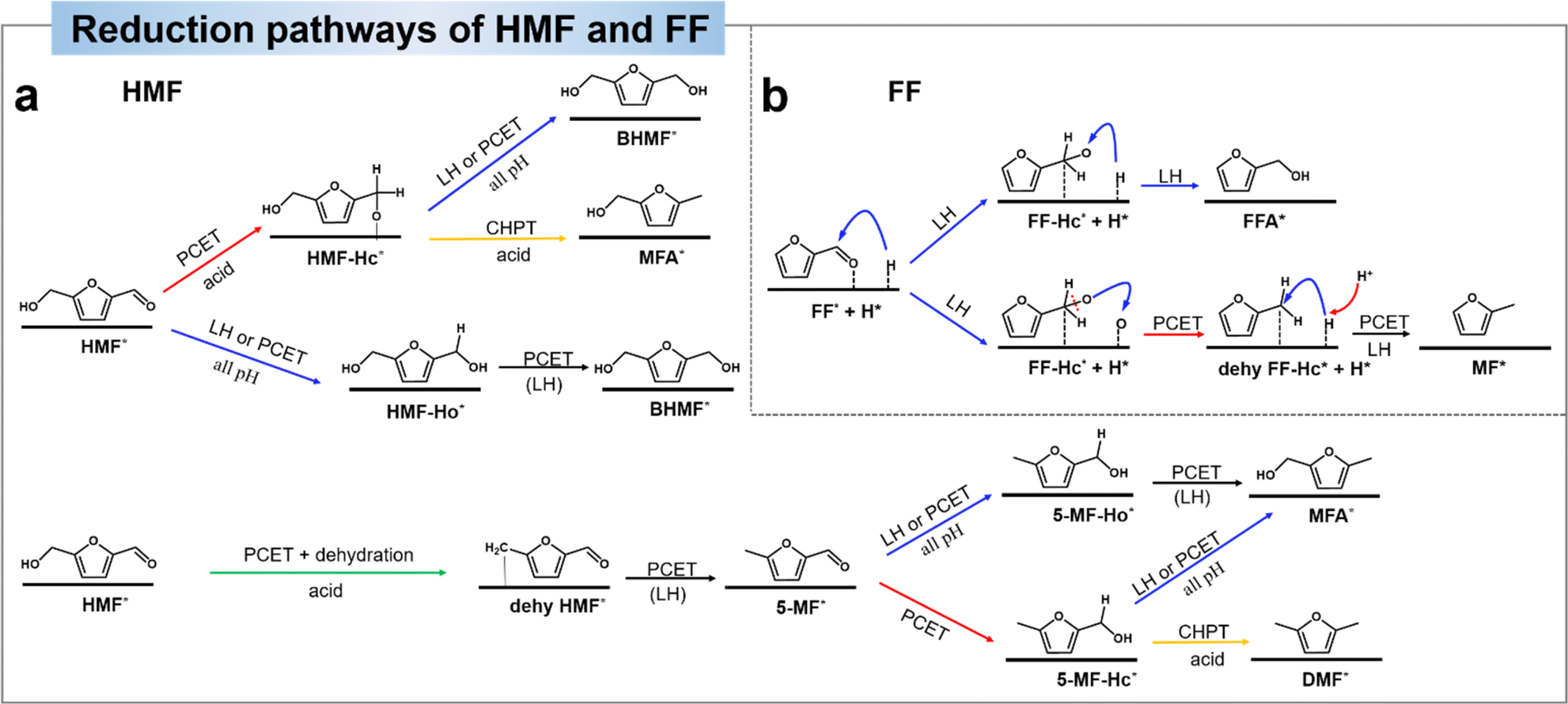
HMF has evolved into a multifunctional molecule capable of being oxidized and reduced to yield chemicals with higher added value.19,20 As illustrated in Fig. 2a, the primary products resulting from the oxidation process include 2,5-diformyl furan (DFF), 5-hydroxymethyl-2-furancarboxylic acid (HMFCA), 5-formyl-2-furancarboxylic acid (FFCA), and 2,5-furandicarboxylic acid (FDCA), each holding promising applications. For instance, HMFCA serves as a valuable monomer in polyester synthesis, while FFCA demonstrates broad prospects in fuel, chemical intermediates, pharmaceuticals, and other industries.21,22 Through hydrogenolysis or hydrogenation, HMF can be transformed into 5-methylfurfural (5-MF) and 2,5-bishydroxymethylfuran (BHMF). 5-MF can then be converted to 2,5-dimethylfuran (DMF) through direct hydrolysis of aldehydes or through the 5-MF → MFA → DMF process (Fig. 2b).23,24 However, the conversion of MFA to DMF is very difficult, because once the alcohol group on HMF is hydrolysed first, it will be difficult for the alcohol group to hydrolysis. Notably, BHMF stands out as a crucial precursor in the production of functionalized polyethers, polyurethanes, and polyamides.25 An essential hydrogenolysis product stemming from HMF is 5-methylfurfuryl alcohol (MFA), and DMF represents an ideal liquid biofuel component for transportation due to its advantageous characteristics, including a high-octane number, a reasonable boiling point, and low solubility in water.4,26,27 | ||
| Fig. 2 The main electro-oxidation pathways (a) and electro-reduction pathways (b) of HMF, and (c) electrochemical conversion pathways of FF. The dashed arrows indicate steps experimentally found to be difficult to occur. | ||
Furfural (FF) stands out as a platform chemical, boasting a commercial production of 250![[thin space (1/6-em)]](https://www.rsc.org/images/entities/char_2009.gif) 000 tons per year derived from the treatment of agricultural waste.28 Due to its chemical and structural complexity, FF offers the potential for direct or indirect conversion into over 80 valuable compounds, primarily through reduction and oxidation processes.29 The pathways for FF transformation into major platform molecules are depicted in Fig. 2c. Among the significant products resulting from FF reduction, furfuryl alcohol (FFA) emerges as an intermediate crucial to pharmaceutical and polymer industries.30,31 Further hydrogenolysis of the side C–O bond of FFA leads to the production of 2-methylfuran (MF), which holds substantial promise as a liquid biofuel with high energy density. Additionally, MF serves as a green solvent and feedstock for the production of pharmaceuticals, pesticides, and perfume intermediates.4,32 On the other hand, FF can undergo transformation to produce furoic acid (FA) via an oxidation process. FF is a versatile chemical for the production of a variety of pharmaceutical drugs, agriculture, fragrances, flavors, biofuels.33
000 tons per year derived from the treatment of agricultural waste.28 Due to its chemical and structural complexity, FF offers the potential for direct or indirect conversion into over 80 valuable compounds, primarily through reduction and oxidation processes.29 The pathways for FF transformation into major platform molecules are depicted in Fig. 2c. Among the significant products resulting from FF reduction, furfuryl alcohol (FFA) emerges as an intermediate crucial to pharmaceutical and polymer industries.30,31 Further hydrogenolysis of the side C–O bond of FFA leads to the production of 2-methylfuran (MF), which holds substantial promise as a liquid biofuel with high energy density. Additionally, MF serves as a green solvent and feedstock for the production of pharmaceuticals, pesticides, and perfume intermediates.4,32 On the other hand, FF can undergo transformation to produce furoic acid (FA) via an oxidation process. FF is a versatile chemical for the production of a variety of pharmaceutical drugs, agriculture, fragrances, flavors, biofuels.33
3 Selective electrochemical oxidation of furan compounds
3.1 Pathway and mechanism for electrochemical oxidation of furan compounds
The electrochemical oxidation of biomass-derived compounds has garnered substantial attention, primarily due to the kinetically unfavorable nature of water oxidation and the relatively low value of its resulting product (O2).34–36 In this section, we will provide an overview and outlook on the electrochemical oxidation of furan compounds. This coverage encompasses the reaction pathways and mechanisms involved, as well as the design principles for electrocatalysts in this context. The determination of electrochemical reaction pathways and mechanisms is crucial for selecting appropriate reaction conditions, improvement of product selectivity and rational design of highly active and selective electrocatalysts. In this section, we will elucidate the electrooxidation pathways and mechanisms, exploring them from the perspective of HMF and FF as substrates, respectively. | ||
| Scheme 1 (a) and (b) OH* mechanisms for electro-oxidation of HMF.37 Copyright 2023, Wiley-VCH. (c) and (d) Schematic dehydrogenation for two indirect oxidation pathways in alkaline aqueous media (RCH2OH represents the organic molecule containing aldehyde/alcohol, M(OH)2 represents low-valence state of the mediator and MOOH represents high-valence state of the mediator).41 Copyright 2021, Royal Society of Chemistry. | ||
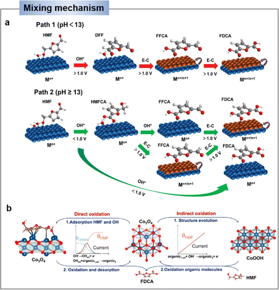
In a strong alkaline environment (pH ≥ 13), the aldehyde group will preferentially adsorb on the catalyst surface, via addition with H2O, HMF will be converted into diol, which then interacts with OH− to activate C–H/O–H and deprotonate to generate carboxyl (i.e., HMFCA). Later on, FFCA is gained through the same OH− activation and deprotonation process on the other alcohol chain. Following, the nucleophilic addition and dehydrogenation steps are repeated to form FDCA (Scheme 1b).44,45 Indeed, the energy of the C–H/O–H bond dissociation of the HMF can be used to assess the oxidative activity of its direct oxidation process. It is important to note that the substrate molecule (HMF) itself needs to be adsorbed on the catalyst surface for the reaction. Therefore, the balance of substrate molecule and OH− adsorption on the electrode surface is identified as an important factor determining the efficiency of direct oxidation.45
 | ||
| Fig. 3 (a) Schematic E–C mechanism of indirect oxidation mediated by heterogeneous redox mediator (Mn+ represents low valence state and Mn+1 represents high valence state of the mediator, A represents substrate). (b) Schematic illustration of HMF oxidation reaction (HMFOR) mechanism on Ni(OH)2 electrode.46 Copyright 2020, Elsevier. | ||
As an example, Wang's group46 demonstrated that the indirect oxidation of nucleophilic reagents via a proton-coupled electron transfer (PCET) process on β-Ni(OH)2. β-Ni(OH)2 is first oxidized to Ni2+δO(OH) on electrode surface, and then Ni2+δO(OH) acquires protons and electrons from the nucleophilic reagent. Consequently, the nucleophilic reagent is oxidized while Ni2+δO(OH) is re-reduced to β-Ni(OH)2, while the oxidation potential of the nucleophilic reagent is highly consistent with that of Ni2+ (Fig. 3b).46,49 According to reports, a strong alkaline environment (pH ≥ 13) is more conducive to the preferential adsorption of HMF's aldehyde group onto the catalyst surface, leading to its oxidation to form HMFCA. At this point, the high concentration of OH− in the electrolyte is advantageous for the electrochemical oxidation of HMF under low potential, indicating that the elevated OH− concentration in the electrolyte favors the potential-dependent indirect oxidation of HMF. In contrast, under non-strong alkaline electrolyte conditions (pH < 13), due to the much stronger bonding of HMF on the catalyst surface compared to OH−, the medium is difficult to oxidize. Therefore, under non-strong alkaline conditions, the hydroxyl group of HMF is preferentially adsorbed onto the catalyst surface. Through DFF as an intermediate, direct oxidation occurs at the electrode surface. This process usually requires a high potential and does not involve the oxidation–reduction of intermediates.38,50
 | ||
| Fig. 5 Mechanisms of electrocatalytic oxidation of furfural to furoic acid: two-electron pathway (a) and one-electron pathway (b). (c) Proposed reaction pathway and corresponding free-energy diagram for the low-potential furfural oxidation on a Cu (111) surface.59 Copyright 2021, Wiley-VCH. | ||
3.2 Electrocatalysts design for oxidation of 5-hydroxymethylfurfural (HMF)
In the past few years, research efforts have been dedicated to exploring electrocatalysts and processes to improve the selectivity toward a target product and increase its energy efficiency, extensive efforts have been devoted to designing electrocatalyst/electrode structures that optimize the chemisorption of key intermediates toward fast kinetics.36,51,61,62 In recent publications which related to the electrochemical oxidation of furans, most of the reaction substrates have focused on HMF. Therefore, in this section, we will review the electrocatalytic oxidation of HMF. The recent literature on the electrocatalytic oxidation of furans has been studied and the electrocatalytic properties of these catalysts as well as reaction condition have been discussed.| Substrate | Catalysts | Electrolyte | Concentration (mM) | Potential (V vs. RHE) | Conversion (%) | Product/sel. (%) | FE (%) | Ref. |
|---|---|---|---|---|---|---|---|---|
| HMF | Pt foil | 0.1 M NaOH | — | 0.44 | 70 | DFF, ∼26 | — | 70 |
| HMF | Pt | NaHCO3 | — | — | — | DFF, — | — | 66 |
| HMF | Pt | 1.0 M H2SO4 | — | 2.0 | 88.3 | DFF, 13.1 | — | 67 |
| HMF | Pt | 0.3 M NaClO4 | — | 0.73 | 9.0 | DFF, 4.0 | 9.0 | 68 |
| HMF | PtRu | 0.1 M H2SO4 | 100 | — | 25 | DFF, 89 | — | 44 |
| HMF | Ru1-NiO | 1.0 M PBS | 50 | 1.5 | 72.4 | DFF, 90 | 70 | 51 |
| HMF | MnOx | H2SO4 (pH = 1) | 20 | 2 | 95.8 | DFF, — | — | 71 |
| HMF | Co8Ce2Ox | 0.1 M Na2B4O7 | 5 | 1.5 | — | DFF, 92 | 48.7 | 72 |
| HMF | Cu NPs | 0.1 M KOH | 10 | 1.23 | — | FFCA, 67 | 113 | |
| HMF | Au/C | 0.1 M KOH | 20 | 0.9 | 100 | HMFCA, — | — | 73 |
| HMF | Cu | 1 M KOH | 50 | 0.4 | ∼70 | HMFCA, 100 | 100 | 43 |
| HMF | Ru1-NiO | 1 M KOH | 50 | 1.3 | — | HMFCA, 74 | — | 51 |
| HMF | Co(OH)2–CeO2 | 0.1 M PBS (pH = 7) | 10 | 1.4 | ∼96 | HMFCA, 89.4 | — | 76 |
| HMF | CoOx | 0.1 M KOH | 5 | 1.6 | — | HMFCA, 48 | — | 52 |
| HMF | Pd1Au2/C | 0.1 M KOH | 20 | 0.9 | 100 | FDCA, 83 | — | 73 |
| HMF | Pd7/Au7 | 1.0 M KOH | 5 | 0.82 | ∼42.4 | FDCA, 38.7 | 85.8 | 74 |
| HMF | Co1Cu1–CH | 1.0 M KOH | 10 | 1.42 | 99.57 | FDCA, 99.91 | 98.88 | 114 |
| HMF | Ni NPs | 0.1 M KOH | 10 | 1.5 | — | — | — | 115 |
| HMF | Ni/CP | 0.1 M KOH | 5 | 1.36 | 99.7 | FDCA, 99.4 | 99.4 | 61 |
| HMF | hp-Ni | 1.0 M KOH | 10 | 1.423 | — | FDCA, — | 98 | 116 |
| HMF | NiCu NTs | 1.0 M KOH | 20 | 1.424 | ∼100 | FDCA, 99 | 96.4 | 78 |
| HMF | Ni–Cu/NF | 1.0 M KOH | 50 | 1.45 | — | FDCA, 100 | 99.7 | 79 |
| HMF | Rh–O5/Ni(Fe) | 1.0 M KOH | 50 | 1.48 | 98 | FDCA, 99.8 | 98.5 | 117 |
| HMF | Ir–Co3O4 | 1.0 M KOH | 50 | 1.42 | — | FDCA, — | 98 | 62 |
| HMF | VO-Co3O4 | 1.0 M KOH | 10 | 1.47 | — | FDCA, — | 88.1 | 40 |
| HMF | NiO–Co3O4 | 1.0 M KOH | 10 | 1.35 | — | FDCA, — | 96.0 | 82 |
| HMF | NiCo2O4 | 1.0 M KOH | 10 | 1.45 | — | FDCA, 99.4 | 99 | 87 |
| HMF | Ni0.5Co2.5O4 | 1.0 M KOH | 50 | 1.5 | — | FDCA, — | 90.3 | 38 |
| HMF | NiO-CMK-1 | 0.2 M KOH | 20 | 1.85 | 65 | FDCA, 79 | 70 | 56 |
| HMF | Pt/Ni(OH)2 | 1.0 M KOH | 50 | — | — | FDCA, — | 98.7 | 89 |
| HMF | CoOxHy | 1.0 M KOH | 10 | 1.5 | — | FDCA, — | 70 | 90 |
| HMF | CF-Cu(OH)2 | 1.0 M KOH | 100 | 1.823 | — | FDCA, — | 100 | 53 |
| HMF | E-CoAl-LDH-NSA | 0.1 M KOH | 10 | 1.52 | — | FDCA, — | 99.4 | 42 |
| HMF | NiFe LDH | 1.0 M KOH | 10 | 1.23 | 98.6 | FDCA, 99 | 99.4 | 118 |
| HMF | d-NiFe LDH | 1.0 M KOH | 10 | 1.48 | 97.4 | FDCA, 99.4 | 84.5 | 92 |
| HMF | CoFe-LDH@NiFe-LDH | 1.0 M KOH | 10 | 1.4 | — | FDCA,100% | 99.8 | 93 |
| HMF | Ru0.3/NiFe-LDH | 1.0 M KOH | 5 | 1.48 | 99.4 | FDCA, 99.2 | — | 94 |
| HMF | NiCoFe LDH | 1.0 M NaOH | 10 | 1.52 | — | FDCA, 88.9 | ∼90 | 54 |
| HMF | NiCoMn LDH | 1.0 M NaOH | 1 | 1.50 | 100 | FDCA, 91.7 | ∼65 | 91 |
| HMF | CoOOH | 1.0 M KOH | 10 | 1.423 | 100 | FDCA, 100 | 99 | 86 |
| HMF | NiOOH | 0.1 M KOH | 5 | 1.47 | — | FDCA, 96.2 | 96 | 47 |
| HMF | MnOx | 0.1 M H2SO4 | 20 | 1.6 | 99.9 | FDCA, — | 34 | 67 |
| HMF | Ni3S2/NF | 1.0 M KOH | 10 | 1.423 | — | FDCA, 98.0 | 98.0 | 103 |
| HMF | Co0.4NiS@NF | 1.0 M KOH | 10 | 1.45 | 100 | FDCA, 99 | 99.1 | 107 |
| HMF | N–MoO2–Ni3S2 | 1.0 M KOH | 10 | 1.623 | 90 | FDCA,100 | — | 119 |
| HMF | Co9S8–Ni3S2@NSOC/NF | 1.0 M KOH | 10 | 1.4 | 100 | FDCA, 98.8 | 98.6 | 120 |
| HMF | NiSx/Ni2P | 1.0 M KOH | 10 | 1.46 | — | FDCA, 98.8 | 95.1 | 109 |
| HMF | NiCo–S | 1.0 M KOH | 10 | 1.45 | 99.1 | FDCA, 98.0 | 96.4 | 121 |
| HMF | Co–P/CF | 1.0 M KOH | 50 | 1.423 | 100 | FDCA, 90.0 | — | 102 |
| HMF | Ni2P NPA/NF | 1.0 M KOH | 10 | — | — | FDCA, 100 | 98 | 104 |
| HMF | NiFeP | 1.0 M KOH | 10 | 1.435 | — | FDCA, 100 | 94.6 | 108 |
| HMF | CoNiP-NIE | 1.0 M KOH | 10 | 1.5 | — | FDCA, — | 87.2 | 122 |
| HMF | MoO2–FeP | 1.0 M KOH | 10 | 1.42 | 100 | FDCA, 98.6 | 97.8 | 112 |
| HMF | NiP–Al2O3/NF | 1.0 M KOH | 0.3 | 1.45 | 98.2 | FDCA, 99.6 | 96 | 123 |
| HMF | NiBx | 1.0 M KOH | 10 | 0.6 vs. NER | 99.8 | FDCA, 99.0 | 99.5 | 105 |
| HMF | NixB (flow cell) | 1.0 M KOH | 10 | 1.45 | 100 | FDCA, 98.5 | 100 | 84 |
| HMF | Ni3N@C | 1.0 M KOH | 10 | 1.45 | — | FDCA, 98.0 | 99 | 55 |
| HMF | Ni3N | 1.0 M KOH | 50 | 1.47 | — | FDCA, ∼92.0 | — | 106 |
| HMF | Ni3N–V2O3 | 1.0 M KOH | 10 | — | — | FDCA, 98.7 | — | 124 |
| HMF | VN | 1.0 M KOH | 10 | 20 mA | 98.0 | FDCA, 96.0 | 84 | 98 |
| HMF | NF@Mo–Ni0.85Se | 1.0 M KOH | 10 | 1.40 | 100 | FDCA, 95.0 | 95.0 | 111 |
| HMF | NiSe@NiOx | 1.0 M KOH | 10 | 1.423 | — | FDCA, 99.0 | 99.0 | 100 |
| HMF | CoO–CoSe | 1.0 M KOH | 10 | 1.43 | — | FDCA, 99.0 | 97.9 | 110 |
| HMF | F–NiCo2O4/CC | 1.0 M KOH | 10 | 1.45 | 98.47 | FDCA, 99.51 | 98.1 | 125 |
| HMF | NiVWv-LMH | 1.0 M KOH | 10 | 1.39 | ∼100 | FDCA, 99.2 | — | 126 |
| FF | PbO2 | 0.05 M H2SO4 | 10 | 2.0 | 100 | MA, 65.1 | 33.4 | 127 |
| FF | CuS | [Et3NH]NO3 (1.8 wt%) | 1 | 1.6 | 70.2 | HFN, 3.6 | 77.1 | 128 |
| FF | Au/C | 0.25 M HClO4 | 50 | 0.8 | — | FA, 99 | 100 | 129 |
| FF | Cu/Cu foam | 1.0 M KOH | 50 | 0.3 V (H-cell) | — | FA + H2, — | 100 | 59 |
| FF | PbO2 | 0.1 M KOH | 10 | 1.3 (Ag/AgCl) | — | FA, 99.3 | 85 | 130 |
| FF | H–PdCu | 0.1 M KOH | 200 | 0.88 (OCV, H cell) | — | FA, — | 93.3 | 131 |
| FF | Ag2O@Ni | 2.0 M KOH | 100 | 1.95 V (OCV) | — | FA, — | — | 132 |
| FF | Pt–Co3O4 | 1.0 M KOH | 50 | 1.55 V | 44.2 | FA, 55 | 66.1 | 133 |
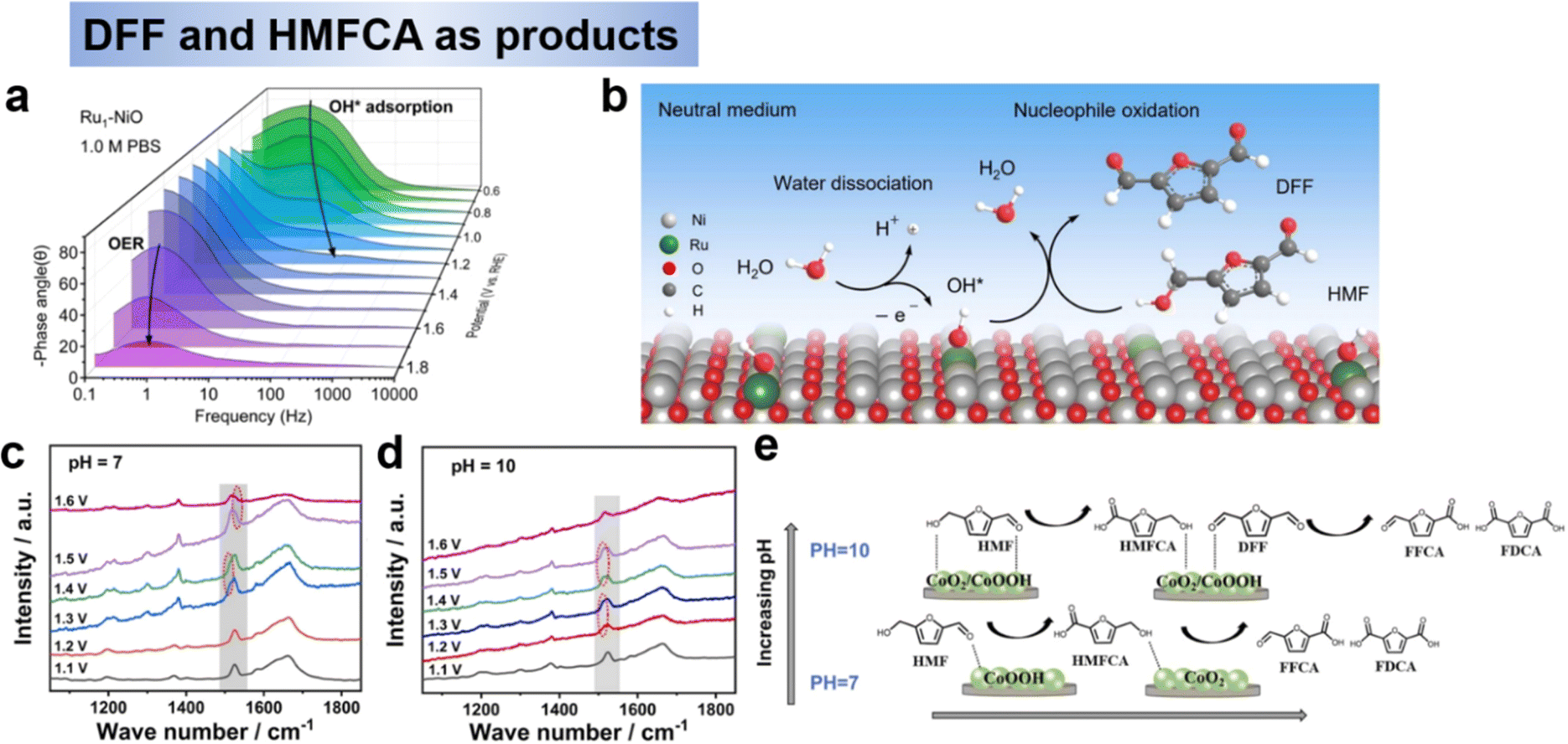 | ||
| Fig. 6 (a) Operando EIS analysis of Bode plots of Ru1-NiO under different potentials and (b) proposed HMFOR mechanism over Ru1-NiO in the neutral medium.51 Copyright 2022, Wiley-VCH. In situ Raman spectra of electrolyte change under different potential at pH 7 (c) and pH 10 (d), and (e) Schematic diagram of HMF conversion path on Co(OH)2–CeO2 catalyst at different pH and potentials.76 Copyright 2023, Elsevier. | ||
In summary, noble metals promote the conversion of HMF to DFF but the efficiency is not satisfactory, which may be due to the theoretical weak adsorption of OH* and strong adsorption H*,71 it is not favorable to the oxidation reaction. Ru has a strong adsorption for both OH* and H*, which is theoretically more suitable for neutral environments and favors water dissociation.72 Therefore, the design of the catalyst, especially the nonnoble metal catalysts, and the highly active and stable hydroxyl oxidation catalysts can be obtained by adjusting the electronic structure and surface adsorption properties. It should be noted that water adsorption and dissociation steps need to be considered to provide active OH*. In addition, the formation of high-valent oxidatively active substances should be avoided to prevent further oxidation of DFF.
For non-precious metal, Zhao et al.76 prepared Co(OH)2–CeO2 as the catalysts for HMF electrooxidation under the neutral condition of pH 7, and achieved HMFCA (89.4% selectivity) at 1.4 V (RHE). XPS and in situ Raman revealed that the evolution of active species between CoOOH and CoO2 is the key factor for the selective electrooxidation of HMF (Fig. 6c and d). The results showed that an increase in pH had a greater oxidizing effect on the oxidation of the alcohol hydroxyl group and that the alcohol hydroxyl group was better oxidized than the aldehyde group. To sum up, pH and potential have a large effect on the oxidation of the alcohol hydroxyl group. At low pH and potential conditions, the oxidation of alcohol hydroxyl groups was significantly inhibited and the products were mainly HMFCA, whereas at high pH conditions theoretically tended to produce FFCA and FDCA. Secondly, the addition of CeO2 and electron transfer from Co(OH)2 to CeO2 led to the formation of more Co3+ substances, which were the key substances catalyzing the oxidation of HMF to generate HMFCA. In addition, as the potential increased, the Co active substance underwent a change from Co(OH)2 → CoOOH → CoO2, with CoOOH being the active substance at low potentials and CoO2 being the active substance at high potentials. At high pH, Co3+ and Co4+ are generated at low potentials, thus oxidizing the hydroxyl and aldehyde groups of HMF, which is the key difference between CoOOH selectively oxidizing aldehyde groups to generate HMFCA at low pH and low potential conditions (Fig. 6e).76 Although not explicitly stated in the text, the reactions involved in this study follow the E–C. For the catalyst design of HMFCA, on the one hand, oxidation-resistant metals or metals with high redox potentials should be selected to avoid the generation of high-valent oxides in alkaline environments, which would be favorable for the further oxidation of HMFCA to FFCA and FDCA. On the other hand, the varied electronic configurations within the same valence state result in distinct selectivity, necessitating further investigation.
Noble metal catalysts. Single metals are difficult for HMF to be completely oxidized to FDCA, while noble metal alloy electrodes can effectively solve this problem. Chadderdon et al.73 synthesized and optimized palladium–gold alloy (Pd1Au2/C) nanoparticles to selectively oxidize both hydroxyl and aldehyde groups of HMF, achieving 83% FDCA selectivity and 100% HMF conversion at an anodic potential of 0.9 V vs. RHE, this excellent performance is due to the presence of the Au phase improves the activity of the isolated Pd, and the activation of aldehydes and hydroxyls by Au and Pd, respectively. A similar study was done by Park et al.74 They further designed a three-dimensional palladium–gold alloy electrode (Pd7/Au7) for HMF oxidation reaction, and finally obtained a 38.7% FDCA selectivity using gold nanoparticles wrapped around palladium nanoparticles in 1.0 mol L−1 KOH and at an anodic potential of 0.82 V vs. RHE. Interestingly, although the alloying elements were the same in the two studies mentioned above, the reaction paths for the formation of FDCA were different. Chadderdon73 believes that the Pd site preferentially undergoes dehydrogenation of HMF to DFF, which is further oxidized to obtain FFCA, and then Au catalyzes the conversion of FFCA to FDCA, while park believes that Au on top preferentially converts the HMF oxidized to HMFCA, while HMFCA → FFCA → FDCA occurs on the Pd site. This may be due to the different morphologies and electronic structures produced by the different preparation methods, resulting in the surfaces being exposed to different crystalline planes, and the different crystalline planes will lead to different adsorption energies of the intermediates, which is the main reason for the difference in selectivity. In addition, one is a flow reactor and the other is a half-cell, and the difference in the reaction vessel will also have an effect, and we encourage the use of uniform criteria for judgement. Although the noble metals showed considerable activity, their post-reaction characterization was insufficient for further active site identification, the material is expensive and the synthesis process is complicated.
Nonnoble metal catalysts. Considering the cost of noble metals and the poor catalytic activity of HMF electrooxidation, although the start-up potentials of nonnoble metal electrocatalysts are slightly higher, the development of highly efficient nonnoble metal catalysts (including nonnoble metal compounds) is still a general trend due to their convenient sources and low prices, and a large number of research results have been produced. Among the various nonnoble metal catalysts, nickel-based and cobalt-based metals are the most active class. Various nickel-based compounds exhibit different compositions and properties, making them adaptable to different applications. Qi et al.61 prepared a nickel nanosheet catalyst vertically anchored on a carbon paper substrate by electrodeposition, which exhibited enhanced catalytic activity in the HMF electrooxidation reaction, with 99.7% HMF conversion and 99.4% FDCA yield at a low potential of 1.36 V vs. RHE. The high catalytic activity was attributed to the unique electronic structure of the Ni/CP electrode. Compared with Ni catalysts with nanoparticle morphology, nanosheet Ni with small grain size can transfer electrons to the semiconducting carbon carriers, and the electron-deficient Ni is easily oxidized to high-valent Niδ+ (δ = 2–3, Fig. 7a and b), especially in the form of NiO or NiOOH at the edge position, which is the key active phase for efficient HMF electrooxidation.77 The reaction of HMF electrooxidation to FDCA may follow both pathways 1 and 2 as mentioned in Section 2.1. In addition to single-metal Ni catalysts, alloy catalysts have also been used to promote the oxidation of HMF to FDCA. To further promote the activity of the HMF oxidation reaction, the design of bimetallic catalysts is a strategy. Zheng et al.78 reported a bimetallic catalyst, Cu-doped Ni nanotubes (NiCu NTs, Fig. 7c), for the oxidation of HMF to FDCA with simultaneous precipitation of H2 at the cathode. When being employed as an anodic catalyst for the oxidation of HMF to FDCA, NiCu NTs showed 100% HMF conversion and 99% FDCA yield in 1.0 M KOH. To gain more insight into the working mechanism over the NiCu NTs catalyst, HPLC (Fig. 7d) and in situ Raman spectra (Fig. 7e) were examined, the results demonstrated that the conversion of HMF to FDCA follows the pathway of HMF–HMFCA–FFCA–FDCA, where the aldehyde groups are first oxidized to form a HMFCA intermediate, and the hydroxymethyl groups are consecutively oxidized to yield FFCA and then FDCA, which is consistent with aerobic HMF oxidation reactions. It is widely accepted that the formation of NiOOH on the surface is the first step in the aqueous oxidation of Ni-based catalysts in alkaline media. From this, it can be reasonably deduced that during the oxidation of HMF, the catalyst surface is also first oxidized to Ni3+OOH, which as the active site then rapidly oxidizes the HMF, while Ni3+ is reduced to have Ni2+. Although the electrooxidation reaction of HMF shows increasing potential, the OER is the main competing reaction at high current densities, which leads to low Faraday efficiency (FE) of the product and catalyst detachment from the electrode. In order to inhibit the OER, Sun et al.79 reported a bimetallic Ni–Cu electrocatalyst (Ni–Cu/NF) loaded on Ni foam to enhance the oxidation reaction of HMF (Fig. 7f). A current density of 1000 mA cm−2 could be achieved at the reversible hydrogen electrode, and both FE and yield remained close to 100% over a wide range of potentials (1.4–1.55 V vs. RHE) (Fig. 7g). In situ Raman and theoretical calculations show that Cu doping hinders the deprotonation of OH* to O*, thus greatly inhibiting the OER process. Meanwhile, from the EIS and Raman results, NiOOH acts as the active site for HMF oxidation, following the reaction path with HMFCA as the intermediate (Fig. 7h and i). From the above results, it can be inferred that metal catalysts usually consist of in situ derived hydroxides or hydroxyl oxides as the active substances for the generation of FDCA, and therefore need to be driven by high potentials. The mechanism (OH* or E–C mechanism) is followed by both active species and pH versus oxidation potential, and some multisite catalysts may incorporate both of the above mechanisms, which requires further testing and calculations.
 | ||
| Fig. 7 Chemical states of Ni/CP hybrid electrodes: (a) first derivative normalized XANES spectra at the Ni K-edge for samples and (b) Ni 2p3/2 XPS spectra of Ni(NS)/CP and Ni(NS)/CP-used.77 Copyright 2021, Wiley-VCH. (c) Schematic illustration of the preparation route for the porous NiCu NTs electrode, and SEM images and (d) relative change (%) of HMF conversion and product yield during the electrooxidation process and (e) Raman spectra in HMF solution.78 Copyright 2022, American Chemical Society. (f) FE-SEM and TEM image of Ni–Cu/NF and (g) FE and yields of FDCA, (h) in situ Raman spectroscopy of Ni–Cu/NF and (i) Gibbs free energy diagrams of HMFOR on m-Ni-Cu/NF.79 Copyright 2023, Wiley-VCH. | ||
Metal oxides, –hydroxides, –oxyhydroxides. Metal oxides have a great advantage in oxidation reactions due to their flexibility in chemical composition and electronic states.80 The most studied oxides are nickel- and cobalt-based oxides because of their excellent adsorption properties.81 Further studies have found that NiO(OH)ads or NiOOH to be the active centre of HMF oxidation.56,81,82 Nickel-based materials have relatively high onset potentials for HMF electrooxidation, usually around 1.30 V vs. RHE.82–85 In contrast, cobalt-based electrocatalysts typically possess a lower onset potential for the electrocatalytic oxidation of HMF.86 Co3O4 were selected as catalysts to investigate the and optimized the HMF adsorption behavior by Wang's group.40,62 First, the adsorption behavior of HMF on Co3O4 was optimized by introducing Ir single-atom sites, as shown in Fig. 8a. Compared with Co3O4, the Ir–Co3O4 electrocatalyst showed a stronger adsorption of HMF through the C
C group (Fig. 8b), resulting in Ir–Co3O4 showed a higher yield (98%) and faradaic efficiency (98%).62 Since the HMFOR process includes the oxidation of hydroxyl and aldehyde groups, the different adsorption energies and positions of OH on the catalyst have an important effect on the activity of HMFOR, and there is also competition for the adsorption of OH by OER. Therefore, Wang et al. developed an oxygen vacancy on Co3O4 catalyst (VO-Co3O4) to solve the competition for the adsorption of OH. As show in Fig. 8c, due to the introduction of oxygen vacancies (VO) in Co3O4, OH−can fill into VO in the VO-Co3O4 lattice. The involvement of lattice OH− not only breaks the competitive adsorption between OH− and HMF, but preferentially couples with organic molecules through lattice oxygen oxidation reaction rather than competing with HMF for adsorption on metal sites, which is the mechanism on Co3O4 electrode (Fig. 8d), thus accelerating the rate-determining step of HMFCA hydrogenation.40
 | ||
| Fig. 8 (a) Scheme of the fabrication of Ir–Co3O4 and (b) the adsorption model of HMF molecules on Ir–Co3O4.62 Copyright 2021, Wiley-VCH. (c) The reaction mechanism of HMFOR on VO-Co3O4 and (d) on Co3O4.40 Copyright 2022, Wiley-VCH. (e) Electrochemical behavior of FAOR on Co3O4, NiO, Fe2O3, and MnO2 electrodes.38 Copyright 2022, American Chemical Society. (f) Activity comparison for HMFOR, FAOR, and FFOR.38 Copyright 2022, American Chemical Society. | ||
Spinel oxides (AB2O4) have received much attention due to their abundant active sites, tunable coordination structures and high electrocatalytic stability, and their octahedral and tetrahedral sites play different roles in HMFOR.87 In previous work, HMF was taken as a whole, thus, the reaction activity of the aldehyde (–CHO) and hydroxyl (–OH) groups has not yet been distinguished.50 In order to deeper understanding of the reaction mechanism for HMFOR, Wang et al.38 designed Ni0.5Co2.5O4 catalysts for the reactivity of aldehydes (–CHO) and hydroxyls (–OH) to gain insight into the reaction mechanism. It was found that the direct oxidation activity of HMF was highly dependent on the activity of hydroxyl groups and aldehydes on the catalyst. The results showed that NiO has high hydroxyl oxidation activity and Co3O4 has high aldehyde oxidation activity (Fig. 8e). By introducing Ni into the tetrahedral sites of Co3O4, the best HMFOR performance was obtained at the Ni0.5Co2.5O4 electrode (Fig. 8f), resulting in 92.4% FDCA yield and 90.4% Faraday efficiency. It is worth noting that Ni doping also changes the reaction mechanism to direct oxidation, with the aldehyde group still oxidized preferentially in 1 M KOH to produce HMFCA, while hydroxyl oxidation was preferred at pH = 13.38 Overall, metal oxide catalysts need to be further enriched due to their flexible and tunable structures. In addition, there is a need to develop methods to improve the performance of oxides, such as performing elemental doping and constructing heterojunctions in order to improve the adsorption and electron transfer to the reactants during the reaction process.
In addition, nickel hydroxide electrodes are more suitable for prolonged alkaline electrocatalysis due to the abundance of hydroxyl groups, which provide active sites and strong adsorption of substrates.88 However, the surface HMFOR of nickel-based catalysts is still limited by the lower rate of Ni(OH)O generation from the active intermediate. Thus, Wang et al.89 adjusted the adsorption energy of Ni(OH)2 with HMF through the introduction of Pt, and explored the transformation of active species Niδ+ in the process of HMFOR. In particular, operando Raman spectroscopy confirmed that Ni(OH)2 was electrooxidized to Ni(OH)O, which further oxidized HMF to FDCA without the formation of NiOx(OH)y (Fig. 9a, the peak at 473 and 553 cm−1), that is considered to be the active substance of OER (Fig. 9b). It can be seen that the HMFOR on the Ni(OH)2 catalyst surface follows the E–C mechanism.89 Since the mechanism of CoOxHy is different from that of Co3O4, Luo et al.90 combined experimental and a theoretical study to explain that electrogenerated Co3+ and Co4+ species act as chemical oxidants but with distinct roles in selective HMF oxidation. It was found that Co3+ generated at a low potential acted as the only oxidant to oxidize the aldehyde group, and as the potential increased, the selectivity of FDCA increased with concentration of Co4+ increased, which indicated that Co4+ was essential for the initial oxidation of the hydroxyl group in the molecule. It was found that the reaction was “E–C” mechanism (Fig. 9c).90
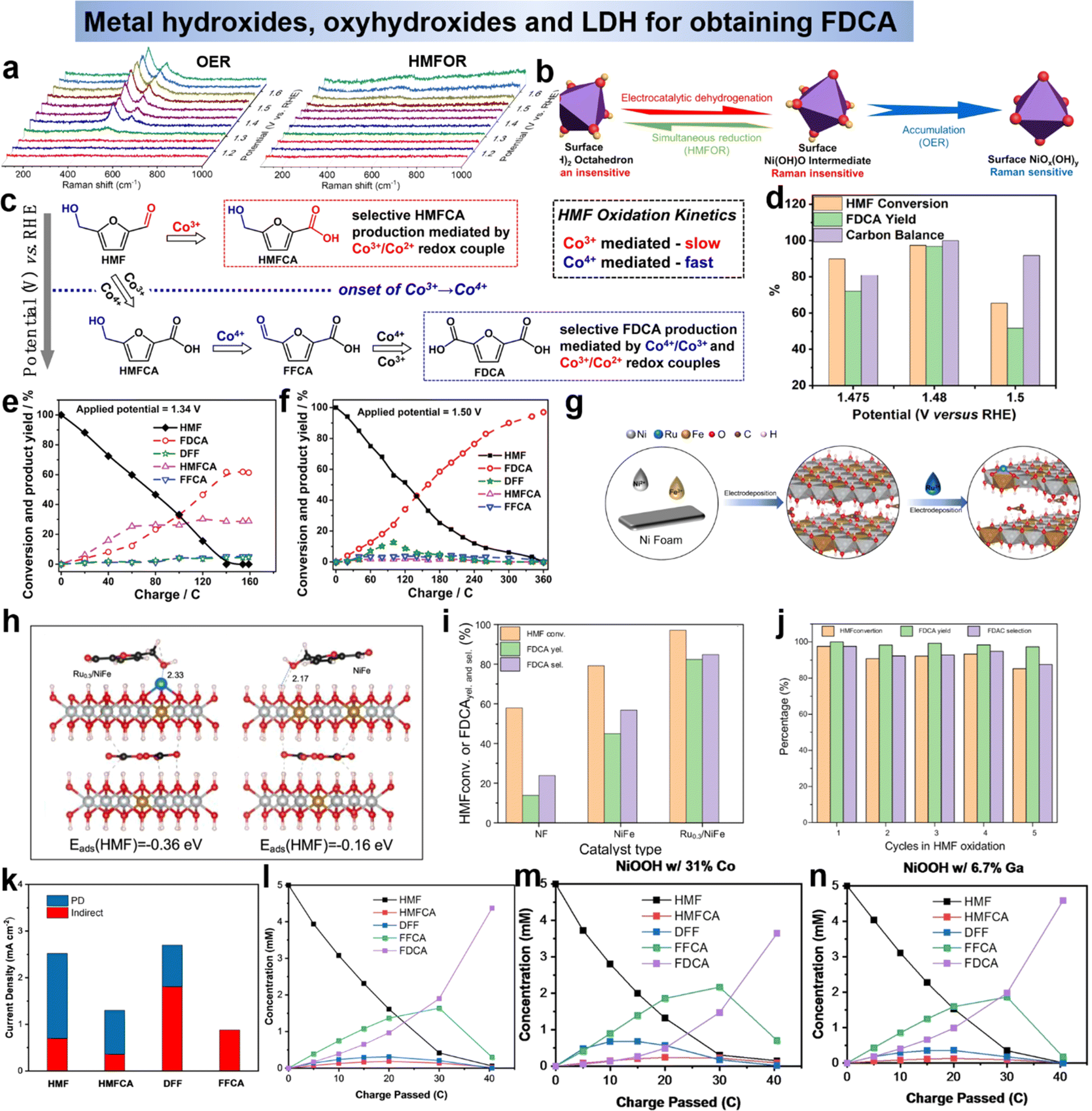 | ||
| Fig. 9 (a) Operando Raman spectroscopy during OER and HMFOR and (b) schematic representation of crystal structure transformation.89 Copyright 2021, Wiley-VCH. (c) Mechanistic illustration of the PD oxidation of HMF.90 Copyright 2021, Wiley-VCH. (d) HMF conversion, FDCA yield, and carbon balance under different applied voltages catalyzed by d-NiFe LDH.92 Copyright 2021, American Chemical Society. Variation of conversion ratios of HMF, DFF, HMFCA, FFCA and FDCA with consumed charges at the potentials of 1.34 V vs. RHE (e) and 1.50 V vs. RHE (f).93 Copyright 2021, Wiley-VCH. (g) Schematic of the preparation process of Ru0.3/NiFe and (h) side view of HMF adsorption configuration and corresponding adsorption energy in both models.94 Copyright 2023, Elsevier. (i) The effects of different catalysts on HMF conversion, FDCA selectivity and yield and (j) HMF selectivity, FDCA conversion and selectivity obtained by Ru0.3/NiFe in HMF oxidation.94 Copyright 2023, Elsevier. (k) Component of the current due to indirect (red) and PD (blue) oxidation in a pH 13 solution.95 Copyright 2022 Wiley-VCH. (l)–(n) Change in concentration of HMF and its oxidation products using pristine, Co-containing, and Ga-containing NiOOH.95 Copyright 2022, Wiley-VCH. | ||
Furthermore, the layered double hydroxide (LDH) has been reported to have superior catalytic performance over single metal hydroxide since the second metal atoms could tune the electronic structure and introduce optimal surface chemical properties.42,54,91 Subsequent studies on LDHs have focused on modulating the electronic structure to inhibit the OER competition response. Wang et al.92 reports the electrooxidation of HMF to FDCA catalyzed by carbon paper supported cationic defect-rich nickel–iron alloy LDH (d-NiFe LDH/CP) under alkaline conditions. The d-NiFe LDH/CP exhibits excellent catalytic performance due to the electronic structure change induced by vacancy implantation. At a voltage of 1.48 V vs. RHE, the conversion of HMF was 97.35%, and the yield of FDCA reached 96.8% with a Faraday efficiency of 84.47% (Fig. 9d).92 Zhao et al.93 have prepared CoFe-LDH@NiFe-LDH as the catalysis for HMFOR, it was shown that the synergistic action of multiple active species could promote the electrooxidation of HMF, and the reactive species of the reaction was M3+ (M = Ni, Co, Fe). The HMF reaction on CoFe-LDH@NiFe-LDH electrodes contained two pathways, namely the HMFCA pathway at low potentials and the DFF pathway at high potentials (Fig. 9e and f). Additionally, Li's group94 loaded single atom Ru on NiFe-LDH to enhance the catalytic ability of NiFe-LDH (Fig. 9g). As shown in Fig. 9h, the electron cloud around Ru3+ was transferred to Fe3+, Ru3+ attracted the electron cloud of Ni2+, and the loaded Ru atoms optimized the adsorption energy of the catalyst for HMF through electronic structure adjustment. The introduction of Ru in HMFOR not only promotes the oxidation of the hydroxyl group in HMF, but also the oxidation of the aldehyde group in FFCA, and in optimal conditions Ru0.3/NiFe exhibits excellent HMF conversion (99.43%), FDCA selectivity (99.24%) and yield (98.68%) in HMFOR (Fig. 9i) and maintained excellent cycling performance (Fig. 9j). Although LDH has good HMFOR activity, especially when it is exfoliated into multilayer or monolayer structures, which can maximally expose its active sites and thus optimize its electrocatalytic performance. However, LDH nanosheets are easily detached and reaggregated in practical applications, so the preparation of monolayer LDH is a challenge that might be improved by the construction of self-supporting structures. Secondly, LDH catalysts require clearer identification of active sites due to their complex composition and structure. Outside of this occasion, LDHs lack stability when exposed to highly alkaline electrolyte solutions for long periods of time. Therefore, methods to further improve the catalytic performance of LDHs for HMF electrooxidation (e.g., design defects) should be developed.
By summarizing the metal hydroxides in the above research, we learn that most of the active species of that are oxyhydroxides (MOOH). In order to gain a deeper understanding of the reaction mechanism of oxyhydroxides and to develop strategies to improve its performance, two of its mechanisms were explored using Ni(OH)2/NiOOH as a model. Impressively, the indirect mechanism we mentioned above, the Ni(OH)2 is first oxidized to NiOOH under applied bias. Then NiOOH acts as a chemical oxidant with the alcohol by non-electrochemical transfer of hydrogen atoms to react with the alcohol by transferring the carbon from the α-position of the alcohol to the Ni3+ site in NiOOH, thus reducing NiOOH back to Ni(OH)2 (Scheme 1d).47 In this case, the applied voltage does not directly drive the oxidation of the HMF, but is only related to the regeneration of NiOOH. In addition to the well-known indirect mechanism, there is a second potential-dependent oxidation mechanism (direct mechanism), whereby oxidation reactions can also occur at potentials more positive than those required for the Ni(OH)2/NiOOH transition. It was thought in the early days that the NiOOH remains in the NiOOH state throughout the oxidation process,47 however, Choi et al.39,95 showed that the second pathway is only active when Ni4+ is present and that it involves hydride transfer from the carbon at the α-position of the alcohol to those Ni4+ sites (Scheme 2). For the second pathway, the application of the potential is required not only to generate active Ni4+ sites but also to drive the hydrogenation reaction. Therefore, the oxidation rate via this pathway is potential-dependent, and even if Ni4+ is still present, the oxidation rate drops to zero as soon as the bias potential is no longer applied. Therefore, this pathway named as potential-dependent (PD) oxidation. Although using NiOOH as model to discuss the differences between the indirect and PD oxidation mechanisms, they believe that both mechanisms are equally applicable to other MOOH catalysts, except that the propensity for indirect and PD oxidation will vary depending on the type of MOOH. Once this is fully understood, the selection and tailoring of electrocatalyst materials to facilitate either the PD or indirect pathway may provide a way to control functional group selectivity. Choi's group95 demonstrated that DFF and FFCA (containing only aldehyde groups) were oxidized via the indirect pathway and HMFCA (containing only alcohol groups) via the PD pathway. For HMFs containing both aldehydes and alcohols, which oxidation pathway dominates (i.e., which group tends to be oxidized first) depends on the oxidation conditions. Under open-circuit conditions that allowed only indirect oxidation, the aldehyde group was preferentially oxidized, resulting in the generation of HMFCA over DFF. However, when 0.55 V vs. Ag/AgCl was applied, resulting in the dominance of PD oxidation and preferential oxidation of the alcohol group to form DFF (Fig. 9k). They also examined the effect of shifting the Ni(OH)2/NiOOH peak position on HMF oxidation by compositional adjustment of NiOOH (Fig. 9l–n). The Ni(OH)2/NiOOH potential directly affects the indirect oxidation rate of HMF, but it did not have much effect on the indirect oxidation of FFCA, since the oxidative adsorption of FFCA is the rate-determining step.95
 | ||
| Scheme 2 Proposed PD oxidation mechanism of alcohols to aldehydes via hydride transfer.96 Copyright 2021, American Chemical Society. | ||
Metal borides, nitrides, phosphides, sulfides, and selenides. Combining with non-metallic elements can further improve the performance of metal-based catalysts. Recently, much effort has been devoted to the construction of transition metal catalysts for HMF oxidation, such as borides,84,97 nitrides,98 phosphides,99 chalcogenides,100 due to their accessible regulation of electronic structure and high earth abundance. In addition to this, these catalysts can provide/enhance the catalytic active sites and expand the pH range of applicability.83,84,100,101 This class of materials was shown to have the actual active substance as MOOH, with the high valence metal acting as the active site to promote the oxidation of the furan compounds, and a gradual increase in the high valence species with increasing applied voltage.102–106 In addition, metal doping leads to a dramatic increase in electrochemical active surface area (ECSA), which permits the exposure of more active sites and effectively modulates the electronic properties of this class of metal compounds, facilitating the rapid reconstruction of the surfaces as (oxy)hydroxides as the actual active sites.107,108 By modulating the electronic structure of the catalyst, the d-band center of the active metal can be adjusted to an optimal position, thus balancing HMF adsorption and dehydrogenation. For example, NiSx/Ni2P,109 CoO/CoCe,110 Mo–Ni0.85Se,111 and MoO2–FeP112 catalysts exhibited superior HMF oxidation performance.
In summary, a wide variety of non-noble transition-metal oxides, hydroxides, and oxyhydroxides (including S, P, B, N, Se compounds) have been studied as electrocatalysts for HMF oxidation. There are some notable differences in their reactivity compared to noble metal catalysts. A major reason for this is that non-precious transition metal compounds typically produce FDCA as the main product, rather than stopping at a partial oxidation product. Based on the comprehensive overview of various catalysts, the following conclusions can be drawn. Firstly, DFF is suitable for generation under non-alkaline environment, while HMFCA is more suitable for generation under non-acidic conditions. Secondly, the noble metals in the catalysts for generating FDCA have smaller potentials but poorer selectivity, but non-precious metal catalysts suffer from the problem of instability in acidic environments. Then, the active site and reaction mechanism of HMF oxidation for generating FDCA can be summarized as follows: (1) medium potential via M2+/M3+ indirect oxidation. (2) Coexistence of direct oxidation at low potential and indirect oxidation at medium potential. (3) There may also be high potential oxidation directly or indirectly via M3+/M4+ (e.g. NiOOH/CoOOH).
3.3 Electrochemical oxidation of furfural (FF)
FF can be oxidatively converted to a variety of value-added chemicals such as FA, MA and HFN, which have a wide range of applications in products such as polyester resins, surface coatings, solvents, plastics, food additives and pharmaceuticals. Holewinski et al.134 have investigated the oxidation reaction pathway of furfural on platinum catalyst in an acidic electrolyte. They found that the selectivity of the electrooxidation of furfural depended on the potential. The major products were FA and 5-hydroxyfuranic acid (HFA) below 1.2 V vs. RHE. At higher potentials, the selectivity shifts mainly to 5-hydroxyfuran-2-(5H)-furanone (HFN) with the appearance of maleic acid (MA) and MA is not easily oxidized further once formed (Fig. 10a). Wang et al.59 had coupled anodic low-potential furfural oxidation with cathodic oxygen reduction reaction (ORR) to change electrocatalytic furfural oxidation and hydrogen production from an electrical energy input mode to an electrical energy output mode. Copper metal was employed as an electrocatalyst for low-potential furfural oxidation. An oxidation-electrical reduction method was used to pretreat the Cu foam electrode to increase the electrochemically active surface area to maximize the utilization of the Cu foam electrode (Fig. 10b). The reaction mechanism of this system is shown in Fig. 5b and belongs to the single-electron pathway. The effect of applied potential on the product distribution is shown in Fig. 10c. The FA concentration shows a volcano curve in the potential range of 0.1–0.5 V vs. RHE and peaks at 0.4 V vs. RHE. The decrease in performance at higher potentials may be related to the electrooxidation of the active metal Cu to inactive Cu2O. When higher potentials were applied, the metal Cu showed electrochemical oxidation to Cu1+ (i.e., Cu2O) and the anodic current density decreased dramatically. These results indicate that low applied potentials are favorable for maintaining the active metal characteristics of Cu electrodes. Not coincidentally, Zhang et al. showed experimentally and theoretically that H-PdCu ANs indeed accelerated the oxidation of furfural at an ultra-low potential (0.1 V vs. RHE) to generate H2via H* (aldehyde group release) recombination, realizing hydrogen production from electrical energy input to output (Fig. 10d and e).131 In order to explain the mechanism of furfural oxidation on the catalyst surface, Li et al.135 performed iodide-mediated anodic electrolysis of furfural in a flowing electrolysis. In this system, an “electrochemical–chemical” (E–C) process occurred (Fig. 10f). First, furfural is oxidized to furfuryl anion in the presence of active iodine and a base. At the same time, iodine is reduced to iodide ions and returned to the cyclic reaction while the furfuryl anion is oxidized to FA. Similar work on electrocatalytic oxidation of furfural with simultaneous hydrogen precipitation and coupled ORR on cathodic as discussed above were also reported by other researchers.33,131,133 The above studies on the electrocatalytic oxidation of furfural showed that, the high potential was more favorable for the acquisition of HFN and MA, and the low potential tended to generate FA, and H2 could be generated simultaneously with the oxidation of furfural by a suitable electrocatalytic electrode.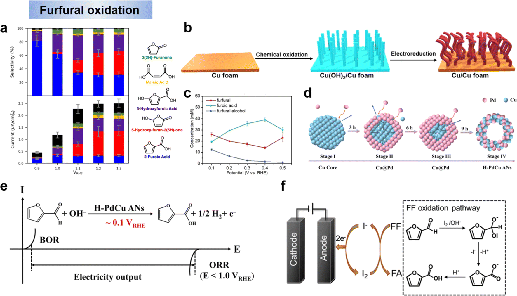 | ||
| Fig. 10 (a) selectivity and partial currents toward major products of the electro-oxidation.134 Copyright 2019, American Chemical Society. (b) Synthesis of the Cu electrode and (c) concentration of the organic compounds in the anode electrolyte as a function of applied potential for chronoamperometric tests over the Cu electrode.59 Copyright 2021, Wiley-VCH. (d) Schematic diagram of the formation mechanism on H–PdCu and (e) the developed electricity output mode.131 Copyright 2023, Elsevier. (f) Schematic diagram of iodide ion-mediated electrochemical oxidation of furfural.135 Copyright 2022, Elsevier. | ||
4 Selective electrochemical reduction of furan compounds
4.1 Pathway and mechanism for electrocatalytic reduction of furan compounds
Electrocatalytic reduction included hydrogenation and hydrogenolysis, as shown in Scheme 3a, where hydrogenation is an addition reaction directed at unsaturated bonds, whereas hydrogenolysis involves the substitution of an H atom for a group (in the presence of a bond break).136 Recent studies on the reduction of HMF and FF have generally shown that in non-acidic media (i.e., near-neutral or alkaline media), hydrogenation is the dominant reaction, whereas hydrogenolysis is promoted only in acidic media.25,137–141 Therefore, in this section, we will provide an overview of the pathway and mechanisms involved in the electrochemical reduction of HMF and furfural under different media conditions and discuss the factors that have an effect on the reaction selectivity.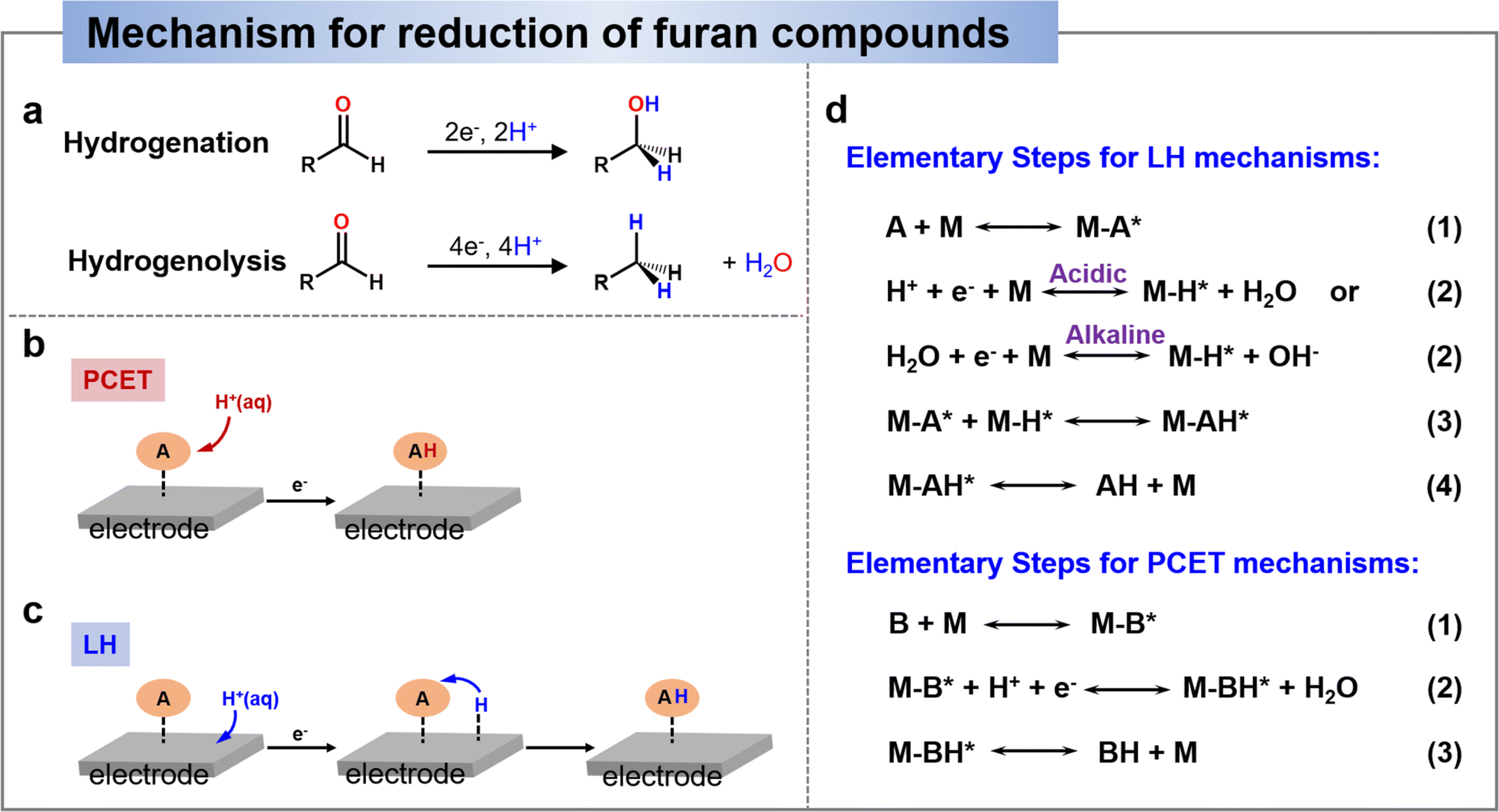 | ||
| Scheme 3 (a) General schemes depicting the hydrogenation and hydrogenolysis reactions.136 Copyright 2022, American Chemical Society. Schematic comparison of adding an H-atom to HMF by the PCET mechanism (b) and by the Langmuir–Hinshelwood (LH) mechanism (c). (d) Elementary steps for LH and PCET mechanisms.142 Copyright 2022, Elsevier. | ||
 | ||
| Fig. 11 (a) Proposed pathways of HMF to DHMF, MF, MFA, and DMF.138 Copyright 2022, Wiley-VCN. (b) Proposed pathways of the electrocatalytic hydrogenation (ECH) of FF on the Cu electrode in acidic electrolytes.142 Copyright 2022, Elsevier. | ||
Similar to HMF, the reduction route of FF is simpler. Zou et al.142 suggested that the hydrogenation step follows the LH mechanism and the hydrogenolysis step includes the LH–PCET mixing mechanism. By spectroscopic tracing of the behavior of the intermediates at the Cu electrode interface, the observed Cu–Oad signals point to a direct C–O dissociation of the alkoxy intermediates during the MF generation process. Based on the experimental data, they analyzed that (1) FA and MF are generated in parallel. (2) The hydrogenolysis product (MF) has significant pH and potential effects in acid solution. (3) Deoxygenated reduction by direct C–O bonding in the hydrogenolysis pathway. The experimental results demonstrated that the hydrogenation and hydrogenolysis of FF were generated mainly through parallel reactions, which excluded all pathways for the dehydrogenation of FFA intermediates to MF, suggesting that FFA is not an intermediate for the generation of MF. The DFT results showed that the leaving mechanism of O intermediates through the PCET pathway was superior to that through the LH pathway, thus confirming the LH–PCET hybrid mechanism for the generation of MF in an acidic environment. Fig. 11b shows the electrochemical reduction route of FF.142 The first hydrogenation step starts with the electrochemically generated Had addition to the adsorbed carbonyl C thereby inducing the formation of FF-Hc* intermediates. The FF-Hc* intermediates can be competitive in that they can be hydrogenated to FFA by a second Had transfer (FFA route) or dissociated to dehy FF-Hc* and Oad (MF route). In the MF route, dehy FF-Hc* is hydrogenated to MF by a second Had transfer, while Oad is further hydrogenated to OHad and H2O by PCET. In summary, MF formation is more favorable in acidic environments due to the fact that PCET is more favorable in environments with more H+.
4.2 Catalysts design for electrocatalytic reduction of furan compounds
The selectivity and Faraday efficiency of HMF and FF electrocatalytic reduction depend mainly on the coverage of active H and organically adsorbed species on the catalyst surface and their rate of conversion, which can be controlled by modulating the cathode catalyst and experimental conditions.144 The catalysts are described below according to the electrochemical reduction products of the furan compounds, and each representative catalyst and electrocatalytic reduction conditions are listed in Table 2.| Substrate | Catalysts | Electrolyte | Concentration (mM) | Potential (V vs. RHE) | Conversion (%) | Product/Sel. (%) | FE (%) | Ref. |
|---|---|---|---|---|---|---|---|---|
| FF | 15%-Cu/NC900 | 1.0 M KOH (pH = 13.6) | 30 | −0.25 | 99 | FFA, 100 | 95 | 152 |
| FF | Cu | 0.1 M Na2CO3–NaHCO3 | 100 | −0.57 | 71 | FFA, 87 | — | 148 |
| FF | Cu1/PC | Acetate buffer (pH = 5) | 40 | −0.75 | — | FFA, — | 90 | 143 |
| FF | Ag60Pd40 | 0.2 M potassium phosphate buffer (pH 6.9) | 100 | −0.5 | 18 | FFA, — | 96 | 158 |
| FAL (FF) | MoS2-DMA | 0.05 M Na2B4O7 solution (pH 9.18) | 35 | −0.25 | — | FFA, >95 | 86.3 | 159 |
| FF | Cu3P/CFC | 1 M KOH (pH = 14) | 50 | 1.4 (cell voltage) | 99 | FA, 100 | >95 | 160 |
| FF | NP-Cu | 0.2 M PBS | 50 | −1.5 V (vs. Ag/AgCl) | 77 | FFA, 96 | 95 | 161 |
| HMF | Cu(OH)2-ER/CF | 0.1 M KOH | 50 | −0.15 | 98.5 | BHMF, 100 | 92.3 | 137 |
| HMF | 15%-Cu/NC900 | 1.0 M KOH (pH = 13.6) | 30 | −0.25 | 81 | BHMF, 94 | — | 152 |
| HMF | Aggd | 0.5 M borate buffer (pH = 9.2) | 20 | −0.56 | 37 | BHMF, 99 | 99 | 146 |
| HMF | Ag/C | 0.5 M sodium borate buffer (pH = 9.2) | 20 | −0.56 | 42 | BHMF, 90 | 95 | 149 |
| HMF | AgCu | 0.5 M borate buffer (pH = 9.2) | 20 | −0.56 | 53 | BHMF, 87 | 95 | 156 |
| HMF | Ag/Cu foam | 0.5 M sodium borate buffer (pH = 9.2) | 20 | −0.51 | 90 | BHMF, >99 | 94 | 154 |
| HMF | Ag/Cu foam | 0.5 M sodium borate buffer (pH = 9.2) | 50 | −0.51 | 99 | BHMF, 83 | 85 | 154 |
| HMF | Ag/Cu foam | 0.5 M sodium borate buffer (pH = 9.2) | 100 | −0.51 | 99 | BHMF, 68 | 70 | 154 |
| HMF | Ag/Cu GD | 0.5 M borate buffer (pH = 9.2) | 50 | −0.51 | 99 | BHMF, 87 | 85 | 157 |
| HMF | Ru1Cu | 0.5 M PBS (pH = 7.0) | 20 | −0.3 | 87.3 | DHMF, 97.5 | 85.6 | 25 |
| HMF | Ru1Cu | 0.5 M PBS (pH = 7.0) | 50 | −0.5 | 92.4 | DHMF, 97.0 | 89.5 | 25 |
| HMF | Ru1Cu | 0.5 M PBS (pH = 7.0) | 100 | −0.5 | 97.1 | DHMF, 89.7 | 88.0 | 25 |
| HMF | MoS2-DMA | 0.5 M sodium borate buffer (pH = 9.2) | 35 | −0.25 | 30 | DHMF, >99 | 75 | 159 |
| HMF | OD-Ag (H-cell) | 0.5 M sodium borate buffer (pH = 9.2) | 20 | −0.56 | 37 | BHMF, 91.7 | 56.2 | 162 |
| FF | Cu | 0.5 M H2SO4 | 30 | — | — | MF, 80 | — | 163 |
| FF | Cu/Cu-400 nm | 0.5 M H2SO4 | 100 | −0.8 | — | MF, — | 73 | 164 |
| −0.65 | 64 | |||||||
| FF | Cu1/PC | Acetate buffer (pH 5) | 40 | −0.9 | — | MF, — | 60 | 143 |
| FF | CuPd0.021/C | 0.1 M acetic solution (pH 2.9) | 40 | −0.58 | — | MF, — | 75 | 165 |
| FF | Ni–Cu | 0.5 M H2SO4 (pH 0.5) | 40 | 10 mA cm−2 | — | MF, — | 59 | 140 |
| FF | Carbon paper | 0.1 M KOH (pH 13) | 100 | −0.41 | — | HDF, ∼100 | 93 | 166 |
| FF | Pd black | 1 M H2SO4 | 0.1 M (membrane reactor) | 200 mA cm−2, 1 h | 100 | MTHF, 76 | — | 167 |
| HMF | CuNi | 0.2 M sulfate buffer (pH 2) | 2 g L−1 | −0.46 | — | DMF, 91.1 | 88 | 168 |
| HMF | Pd SA/TiO2 | 1 M PBS (pH 6.8) | 20 | −0.6 | 62.3 | DMF, 90.3 | ∼60 | 169 |
| HMF | TiO2 | 1 M PBS (pH 6.8) | 20 | −0.6 | — | BHH, 70.2 | 169 | |
| HMF | CuO/Fe2O3/CF | 0.1 M KOH (pH = 13) | 10 | 10 mA cm−2 | 72 | MFA, ∼28 | 84 | 170 |
| HMF | Ni | 0.5 M BBS (pH 9.2) | 20 | −0.4 | 40.4 | MFA, 17.8 | — | 145 |
| HMF | Pd/VN/CF | 0.2 M HClO4 | 10 | 20 mA, 45 min | >90 | BHMTHF, >88 | >86 | 98 |
| HMF | Zn | 0.2 M sulfate buffer (pH 2.0) | 20 | −0.89 | — | HD, 72.4 | 81.6 | 171 |
O and C–O bonds on the HMFads (Fig. 12a and b). The elongation of the CO bonds of aldehydes is more significant than that of alcohols, suggesting that the conversion of HMF to MFA is achieved mainly by cleavage of the aldehyde CO bond, rather than by cleavage of the C–O bond after the aldehyde group is first hydrogenated to an alcohol, as shown in Fig. 12c. Once MFA is formed, the alcohol C–O bond is difficult to cleave, and therefore DMF is difficult to form under these conditions. Considerable amounts of Humins were produced when W and Ti were used as reduction catalysts for HMF. These metals bind the strongest to HMF, resulting in significant deformation of the furan ring as well as significant elongation of the C–O and CO bonds (green shaded area in Fig. 12b). Too strong adsorption of HMF on the metal surface will cause an increase in the coverage of HMFads on the surface, which will easily generate dimerization products.
 | ||
| Fig. 12 (a) Yields of BHMF, MFA and humins by various metals and (b) adsorption energy of HMF (left axis) and bond lengths (right axis) of the CO and the C–O of HMF and (c) electrochemical conversion pathways of HMF, FAL and FA.145 Copyright 2021, Wiley-VCN. (d) SEM images for typical Cu(OH)2-ER/CF and (e) comparison of the reaction barrier of the RDS for BHMF path and dimer path.137 Copyright 2023, Elsevier. (f) Cu-catalyzed ECH of FF to FA and (g) FF conversion, FA/HFN yields and faradaic efficiency at various potentials and (h) ECH of HMF with Cu/NC900 serial catalysts.152 Copyright 2022, Elsevier. (i) Schematic illustration of synthetic route for Ru1Cu SAA and (j) electrochemical reduction mechanism of HMF over Ru1Cu and Cu.25 Copyright 2022, Wiley-VCN. | ||
Unlike HMF, FF and FFA have only one alcohol or aldehyde group. Therefore, examining their propensity for hydrogenolysis provides a clearer picture of which bond is more susceptible to hydrogenolysis. When W, Fe, Co, Ni, Cu cathodes were used, the aldehyde group of FF underwent both hydrogenation and hydrolysis to give FFA and MF, while the hydrogenation product FFA was obtained with high selectivity when In, Cd, Ag were used as cathodes (Fig. 12c). On the other hand, when FA was reduced, no hydrogenolysis product was detected regardless of metal type. This again illustrates that CO is more hydrogenolytic than C–O bond.145
Based on the mechanistic analysis of the hydrogenation of aldehydes to generate BHMF, it can be seen that the two main competing reactions have been identified: (i) hydrodimerization leading to the formation of a diol, fostered at high substrate concentration, and (ii) hydrogen evolution reaction (HER), promoted at high overpotential. Therefore, the catalyst with appropriate and moderate electrocatalytic activity is highly desirable to achieve efficient and selective conversion of HMF to BHMF or FF to FFA. For example, noble metals, represented by Pt, have a strong hydrogen-removal reaction (HER) capability during water cracking, thus leading to low Faraday efficiency.153 In contrast, transition metals with poor catalytic properties for HER favor the subsequent hydrogenation step.127,154 Cu-based electrodes have attracted the attention of researchers due to their better ability to catalyze HMF and relatively poor HER reactivity, providing a wide potential window and high Faraday efficiency for BHMF.25,137,155 Recently, Wang's group137 reconstructed the surface atomic arrangement of Cu foam by a two-step redox strategy (Fig. 12d), and demonstrated that the key factor controlling the HMF electrocatalytic hydrogenation reaction as well as the product selectivity is the crystallographic effect of Cu (Fig. 12e). Simultaneously, they experimentally confirmed that the hydrogenation reaction of HMF is primarily through the hydrogen atom transfer (HAT) pathway, which is a process requiring surface-adsorbed Hads as the hydrogen source.137 Liu et al.152 reported highly efficient and selective electrocatalytic hydrogenation of FF to FFA with Cu electrocatalyst (Cu/NC900) (Fig. 12f). Under optimal conditions, close to 100% selectivity and 95% Faraday efficiency for FFA and 99% FF conversion were obtained over the Cu electrocatalyst. The effect of potential on product distribution showed that low potentials (−0.05–−0.25 V vs. RHE) mainly promoted the formation of FFA, whereas high potentials (−0.35–−0.45 V vs. RHE) led to a competitive reaction and the formation of HFN (Fig. 12g). Inspired by the above results, the Cu/NC900 series catalysts were further applied in the electrocatalytic hydrogenation reaction of HMF, and 15%-Cu/NC900 exhibited the highest performance for the hydrogenation of HMF under optimal conditions, yielding BHMF in 77% yield and 94% selectivity (Fig. 12h). In addition, Ag has been shown to have good activity for the hydrogenation of furan compounds,146 and combining two metals, Ag and Cu, in an electrocatalyst has been shown to be effective in promoting the hydrogenation of HMF and FF.25,154–158 For HMF hydrogenation to BHMF, it can be carried out either by PCET or via surface-adsorbed H (H*) at the electrode by proton/water reduction (LH pathway). However, HMF hydrogenation often competes with the hydrogen-extraction reaction (HER), leading to a decrease in the FE of BHMF. In order to achieve a balance between FE and hydrogenation activity, Duan et al.25 proposed a Ru1Cu SAA catalyst that efficiently converts HMF to DHMF at lower potentials with enhanced activity and FE (Fig. 12i), where the FE of Ru1Cu to 2,5-dihydroxymethylfuran was 85.6% with a yield of 0.47 mmol cm−2 h−1, much higher than that at −0.3 V vs. RHE, the conversion of BHMF by Cu was 71.3% in a yield of 0.08 mmol cm−2 h−1. This study also demonstrated that the doping of single-atom Ru altered the mechanism of HMF hydrogenation. Due to the higher H2O activation activity of Ru, it can provide the required protons for hydrogenation in situ, independent of the proton concentration in the electrolyte. As a result, the reaction on the Ru1Cu cathode follows the Langmuir–Hinshelwood (LH) mechanism, while the reaction on the Cu cathode tends to follow the Proton-Coupled Electron Transfer (PCET) mechanism, as illustrated in Fig. 12j.
In summary, the electrocatalyst, electrocatalytic performance and electrochemical condition for hydrogenation of furan compounds are listed in Table 2.
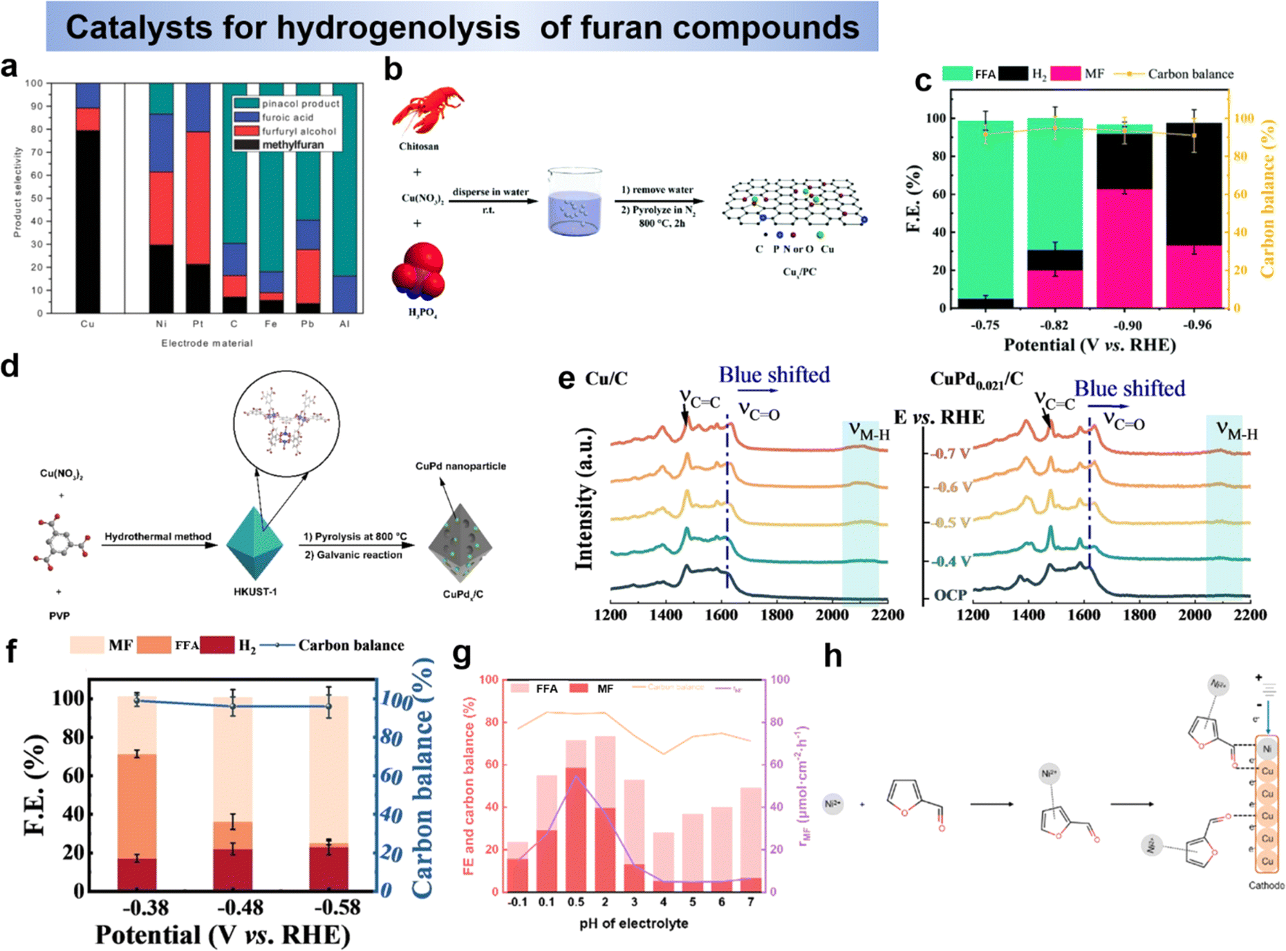 | ||
| Fig. 13 (a) Product composition of the electrocatalytic reduction of furfural at different electrode materials.163 Copyright 2013, Royal Society of Chemistry. Schematic illustration of the fabrication process for the Cux/PC catalysts (b) and Cu1/PC (c) at different applied potentials.143 Copyright 2021, Royal Society of Chemistry. (d) Schematic illustration of the method for the synthesis of CuPdx/C catalyst and (e) potential dependent SERS spectra obtained in situ at Cu/C (left) and CuPd0.021/C (right) and (f) FE and carbon balance data for the bulk electrolysis of furfural obtained with CuPd0.021/C.165 Copyright 2022, Wiley-VCN. (g) The FE, CB, rp of MF varied with the increase in pH value and (h) speculation about the mechanistic roles of the Ni and Cu sites on the electrode.140 Copyright 2023 Royal Society of Chemistry. | ||
C bond in the HMF furan ring can be achieved in acidic media. Li et al. reported the reduction of HMF to BHMTHF by using Pd nanoparticles anchored on vanadium nitride (Pd/VN) as a cathode in 0.2 M HClO4, the selectivity and FE of BHMTHF were >88% and >86%, respectively.98 In this reaction, HMF was first reduced to BHMF, followed by further reduction of BHMF to BHMTHF (DHMTHF). A membrane reactor for the electrochemically driven hydrogenation of furfural to 2-methytetrahydrofuran (MTHF) reaction was reported by Curtis P. Berlinguette et al.167 They showed how the membrane reactor can produce MTHF with >75% selectivity at 200 mA cm−2, compared to the lower selectivity (<35%) and current density (50 mA cm−2) of conventional ECH using a single cell.167 Another remarkable reduction reaction observed in acidic media is the ring opening of furans. The reduction product, 2,5-hexanedione (HD) was produced by the reduction of HMF by reductive furan ring-opening and hydroxymethyl/aldehyde reduction to alkanes. Roylance and Choi reported the electrochemical reduction of HMF to HD on a Zn cathode at ambient temperature and atmospheric pressure in 0.2 M sulfate buffer (pH 2.0) with 81.6% FE and selectivity 72.4%.171
4.3 Factors affecting the electrocatalytic reduction of furan compounds
 | ||
| Fig. 14 (a) Selectivity (left) and FE (right) for products produced by a Cu foam electrode.138 Copyright 2022, Wiley-VCN. (b) FE of corresponding product and the selectivity after electrolysis and (c) reaction pathway for FF on the Cu electrode.142 Copyright 2022, Elsevier. (d) Furfural conversion, hydrofuroin yield, and FE for partial electrolysis conducted at pH 7 and 13.166 copyright 2020, Royal Society of Chemistry. (e) Potentials of THFA, FA, MF, MTHF, and the hydrogen evolution reaction (HER).167 Copyright 2023, Royal Society of Chemistry. (f) Potential dependence reaction pathways for HMFRR.146 Copyright 2016, American Chemical Society. (g) HMF conversion (line) and product selectivity and (h) total charge passed and FE of products and H2.174 Copyright 2021, Wiley-VCN. (i) Preparative electrolysis of furfural with various initial furfural concentrations.172 Copyright 2017, American Chemical Society. | ||
To explain the phenomenon that aldehyde selective hydrogenolysis occurs in strongly acidic electrolytes while aldehyde hydrogenation mainly occurs under alkaline electrolytic conditions, Zou et al.142 systematically explored the effect of electrolyte pH on the selective reduction of furfural. As shown in Fig. 14b, the selectivity of MF decreased from 40.1% to 1.4% and FFA increased from 45.2% to 98.1% after 30 min of current electrolysis at pH ranging from 2 to 8, and no dimerization products were observed.142 This indicates that the selectivity of FFA increases significantly with pH increase, and it is quite difficult to make MF by hydrogenolysis of FFA under electrolytic conditions. Therefore, the hydrogenation and hydrogenolysis products during FF electrolysis were mainly formed by parallel reactions in which FFA was not an intermediate in the generation of MF, as shown in Fig. 14c.
Extrapolating from the reaction kinetics, it was found that acidic conditions (low pH) are more favorable for C–O/CO breaking hydrogenolysis, whereas neutral and weakly alkaline conditions (high pH) are more favorable for hydrogenation. The formation of MF appears to be a hybrid LH-PCET process, and since PCET is affected by the proton donor and the potential, it is difficult for Oad to transfer through Had to generate H2O when there is a shortage of H+, and thus it is difficult to generate MF in neutral or alkaline media.142 In acidic electrolytes, the rate of hydrofuran generation is not affected by pH, and the formation of hydrofuran is more favorable at pH = 13 because alkaline conditions inhibit other competing reactions and facilitate the dimerization of furfural hydrogenation to hydrofuran (Fig. 14d).166 Overall, the selectivity of the reduction products of HMF and FF was related to the pH of the electrolyte, especially for the hydrogenolysis of aldehyde and alcohol moieties. Acidic conditions were more suitable for hydrogenolysis, whereas neutral and alkaline conditions were more suitable for hydrogenation, and different pH led to differences in the mechanism of electroreduction of HMF and FF, with the PCET process being more suitable for acidic conditions.
5 Paired electrolysis of furan compounds
In electrochemistry, oxidative and reductive half-reactions are usually paired with each other, such as the formation of H2 and O2 from the electrolysis of water at the cathode and anode. However, hydrogen and oxygen precipitation reactions (HERs and OERs) are less efficient due to high activation barriers.175 Paired electrolysis is important by converting organics into valuable chemicals, especially for the conversion of alternative OERs under slow kinetic conditions. Combining ideal half-reactions into an efficient catalyst for paired electrolysis maximizes energy efficiency to 200% of theoretical maximum electron efficiency. This approach reduces production costs in the chemical and pharmaceutical fields, but faces challenges such as half-reaction matching, current density mismatch, chemical incompatibility and crossover issues.149 Currently there are several types of paired electrolysis as follows.5.1 Paired electro-oxidation with HER
Molecular hydrogen (H2) is a promising energy carrier due to its high energy density and environmentally friendly properties. Electrolytic water decomposition, with hydrogen precipitation reaction (HER) on the cathode and oxygen precipitation reaction (OER) on the anode, is a cost-effective and carbon-neutral hydrogen production method. However, the slow OER process limits water electrolysis efficiency, necessitating higher voltages (>1.23 V) for H2 production (Fig. 15a).176 To reduce costs, efficient anode reactions, such as biomass electrooxidation, have gained attention. HMF and FF, as biomass platform molecules, are oxidized to produce high-value products, like FDCA. Layered bimetallic hydroxides (LDHs) serve as a typical anode in the electrooxidation of furan compounds with HER.54 Zeng et al.117 developed a bifunctional catalyst, Rh-SA/NiFe NMLDH, showing high activity (1.48 V at 100 mA cm−2) and durability for HMFOR and HER. In 2021, Wang et al.43 reported a bipolar hydrogen production system using Cu as the anode and Pt as the cathode, achieving HMF oxidation to HMFCA at a low potential of 0.1 V vs. REH, releasing H2 at both electrodes, as shown in Fig. 15b. This system requires only 0.27 V for a current density of 100 mA cm−2, significantly lower than conventional HMF electrooxidation coupled hydrogen (1.6 to 1.7 V).43 | ||
| Fig. 15 (a) Schematic representation showing the potential ranges of the OER, EOO, and HER.176 Copyright 2022, Wiley-VCN. (b) Schematic of the two-electrode electrolyser employing low-potential aldehyde oxidation coupling with HER.43 Copyright 2021, Springer Nature. (c) LSV curves of CO2RR with OER or HMFOR and (d) the comparison between a traditional single reaction and paired electrolysis system.177 Copyright 2022, American Chemical Society. (e) Integrated electrolysis cell coupling CO2RR with HMFOR.178 Copyright 2023, Springer Nature. (f) polarization and power curves of HMF-fuel cells and (g) percentage of chemical versus time plot.179 Copyright 2020, Royal Society of Chemistry. (h) LSV polarization curves for NRR coupled with OER and HMF oxidation, and (i) the stability test towards NRR coupled with HMF oxidation.69 Copyright 2019, Royal Society of Chemistry. (j) Demonstration of pairing 4-NBA ERR (left) and 5-HMF EOR (right) in H-type cell by using a solar-driven system.99 Copyright 2022, Springer Nature. (k) Relative concentration of HMF and FDCA and (l) HMF and DHMTHF.180 Copyright 2019, Wiley-VCN. (m) Schematic diagram of linear paired electrolysis of FF to FA.135 Copyright 2023, Elsevier. | ||
5.2 Paired electro-oxidation with CO2RR
Electrolysis of CO2 for the production of high value-added chemicals (HVCs) is a sustainable strategy to address energy and climate issues. To improve CO2RR economics and electrolysis efficiency, the search for a kinetically favorable anodic reaction to replace OER offers promise for sustainable production with high yields, selectivity, reaction rates, and energy consumption. Han et al.177 used PdOx/ZIF-8 as the cathode and PdO as the anode to establish a CO2RR-HMFOR paired electrolysis system that requires only 1.06 V under strongly acidic conditions of starting cell voltage, which significantly reduces the energy consumption compared to the conventional CO2RR-OER system (1.77 V) (Fig. 15c). As shown in Fig. 15d, at a high current density of 103.5 mA cm−2, the CO2RR Faraday efficiency reached 97.0% and the HMFOR organic acid yield was 84.3%, including maleic acid (20.0%) and formic acid (64.3%).177 This paired electrolysis system excelled in terms of FE and current density. However, challenges persist in improving productivity due to different pH requirements for the two electrodes and the competition of OER and HER with HMFOR and CO2RR. Addressing these challenges, Ye et al.178 reported that indium-rich oxygen oxide (InOOH-Ov) is a bifunctional catalyst for CO2 reduction and HMF oxidation, with FEs exceeding 90.0% at both optimized potentials. This catalyst provides a viable pathway for the simultaneous production of valuable chemicals at two electrodes by integrating CO2 reduction and HMF oxidation in an electrochemical cell to form 2,5-furandicarboxylic acid in high yields (both around 90.0%) (Fig. 15e).5.3 Paired electro-oxidation with ORR
Fuel cell technology involves two important chemical reactions, including the fuel oxidation reaction at the anode and the ORR reaction at the cathode. Theoretically, the use of high-performance bifunctional catalysts plays a key role in reducing the reaction energy barrier and improving the reaction efficiency. To this end, Zhang et al.179 designed a direct HMF fuel cell combining ORR and organic synthesis using PtNiSx as a catalyst. The results showed that the close interaction and interfacial effect between Pt and Nisx nanoparticles gave the catalyst excellent ORR and HMFOR activities (Fig. 15f). The discharge efficiency of the HMF-containing fuel cell was 2.12 mW cm−2 and the current density was 6.8 mA cm−2 at 60 °C. In addition, the FE of valuable FDCA at the anode was close to 98% (Fig. 15g).5.4 Paired electro-oxidation with NRR
Ammonia (NH3) is not only an important source for industrial utilization but also an important renewable energy carrier. Electrocatalytic nitrogen reduction reaction for the synthesis of NH3 (NRR) is a sustainable and economically viable process under environmental conditions. Conventional electrocatalytic synthesis of NH3 in alkaline media can be divided into cathodic NRR and anodic OER, and the replacement of OER by oxidation reactions with thermodynamically favorable biomass such as furfural and 5-hydroxymethylfurfural (HMF) throughout the hydrolysis process has been developed as a new strategy. Xu et al.69 used Ru(III)-PEI@MWCNT as a bifunctional catalyst for NRR and HMFOR. After 27 h of stable electrolysis at a current density of 0.50 mA cm−2, the cell voltage was only 1.34 V, which was 220 mV lower than the oxygen precipitation potential, and the Faraday efficiency of the FDCA was maintained at 94%, indicating the excellent performance of NRR-coupled HMF oxidation (Fig. 15h and i). Oschatz's team reported the synthesis of nitrogen boron co-doped porous carbon with a unique pore structure, high thermal atom doping and high oxidation potential.45 The created B–N motifs combine a large number of unpaired electrons and frustrated Lewis pairs, allowing the electronic structure of the B–N motifs to be combined with the electronic structure. They performed well in both electrochemical oxidation of HMF and NRR in the absence of metal additives. The yield of NH3 was stable at 21.3 μg h−1 mg−1, with a FE of 15.2%. The conversion of FDCA was 71% with a yield of 57%.5.5 Paired electro-oxidation with organic reaction
In recent years, in order to improve the energy conversion efficiency, research has focused on coupling electrocatalytic oxidation reactions with small molecule reduction reactions (e.g., HER, CO2RR, NRR, etc.). In addition to coupling the small molecule reduction reaction, matching the rates of organic oxidation and organic hydrogenation at the same time can realize the simultaneous output of high value-added products at both electrodes, improving the catalytic efficiency and eco-efficiency. In recent years, these electrocatalytic oxidation reactions have been combined with electrocatalytic small-molecule reduction reactions (HER, CO2RR, NRR, etc.) to improve the energy conversion efficiency. In addition to coupling with small molecule. For instance, Sun et al. constructed a paired electrolytic system for electrocatalytic oxidation of HMF to FDCA and hydrogenation of p-NP to p-AP, with an excellent conversions and efficiencies.105 Renewable energy driven electrolysis is an effective way to fully utilize energy. Therefore, Yang et al.99 reported solar cell-powered paired electrolysis using solar cell drive at 1.420 V for 4-NBA reduction and HMFOR (Fig. 15j). Successful paired electrolysis of 4-NBA and HMF by constructing FeP–MoP heterojunction electrodes achieved lower voltage reaction than water decomposition, suggesting that the paired electrolysis system is more efficient.Additionally, Pang et al. reported a paired electrolytic system for the electrocatalytic hydrogenation of HMFOR and 4-nitrophenol to synthesize 4-aminophenol.53 The paired electrocatalytic system exhibited excellent reaction performance with excellent yields and Faraday efficiencies. In addition to pairing HMF with other organic substrates for electroreduction, pair electrolysis of HMF as both anodic and cathodic substrates to generate high value-added products has been reported. Li et al.180 successfully prepared three-dimensional vanadium nitride (VN) and Pd/VN hollow nanorods for the electrocatalytic oxidation and hydrogenation reaction of HMF to generate FDCA and DHMTHF with excellent conversion and selectivity (Fig. 15k and l). Different types of pair electrolysis systems such as parallel pair electrolysis, convergent pair electrolysis, divergent pair electrolysis and linear pair electrolysis were proposed by Ibanez et al.181 Almost all of what we mentioned earlier are divergent paired electrolysis, which mainly involves electrode passivation, inconsistent products, and poor compatibility of anodic and cathodic reactions.162 Li reported a redox-mediated linear paired electrolysis system that combines a hydrogen peroxide-mediated cathodic process and an I2-mediated anodic process for the simultaneous conversion of FF to FA (Fig. 15m).135 His linear paired electrolysis has the same substrate at both electrodes and yields the same product at both the anode and cathode, and avoids undesirable water cleavage reactions and furfural reduction side reactions by altering the electrolysis reaction paths, improving the energy reduction and electronic efficiency.
6 Industrial scale development of electrocatalytic conversion of biomass-derived furan compounds
The key to the industrial application of electrocatalytic conversion of furan compounds is the development of high current density catalysts. Up to now, researchers have optimised the electrode design by coupling different metal sites with different activities towards hydroxyl and aldehyde groups on the furan ring, which can achieve the conversion of furan compounds at lower potentials. Taking the oxidation reaction of HMF as an example, although the optimised various catalysts have high conversion and Faraday efficiency, the current density during electrolysis is too low (less than 100 mA cm −2) to meet the requirements of industrial production.38,182 The main reason that currently prevents the industrialisation of electrocatalytic HMFOR is that the electrooxidation reaction competes with OER at high potentials, resulting in a current density of HMFOR that does not gradually increase with increasing voltage. The occurrence of OER at high potential leads to an increase in current density, but the reaction efficiency of HMFOR decreases dramatically. More critically, no clear relationship has been established between catalyst performance and electrolysis efficiency, and there is a lack of a unified theoretical basis on how to design catalysts to achieve high current density, which seriously hinders the improvement of catalytic performance and the research and development of HMFOR. For this reason, Mu et al. proposed segmented i–t measurements within the voltage window to replace the LSV curve to extract the effective current density and obtain the maximum conversion efficiency.183 By comparing the actual current densities, it was found that a lower onset overpotential does not imply that higher current densities can be achieved within the voltage window, and it was confirmed that the proton-coupled electron transfer (PCET) process is the key to influence the anodic peak current. The anodic peak current density achievable within the voltage window is actually a better indicator of catalyst performance than the onset overpotential due to electrolysis efficiency. Based on this, they designed electrode materials capable of achieving current densities above 200 mA cm−2 for HMF conversion. As shown in Fig. 16a, Cr–Ni (OH)2/NF with a Cr doping rate of 1.42% showed a current density of up to 230 mA cm−2 at an HMF concentration of 10 mM, and when the HMF concentration was increased to 20 mM, the current density could reach more than 360 mA cm−2, which showed an extremely high HMF oxidation activity. The electrocatalytic performance of Cr–Ni(OH)2/NF-2 on furfuryl alcohol, furfural and ethanol was also tested (Fig. 16b–d), and the results showed that the modified catalytic material could achieve efficient conversion of substrates, demonstrating the versatility of Cr–Ni(OH)2/NF for electrocatalysis of biomass molecules. This work yielded HMFOR current densities greater than 200 mA cm−2, but still insufficient to reach industrialisation. Therefore, Mu et al. propose a proton transfer-mediated strategy to overcome the energy barrier of the dehydrogenation process of HMF.184 They synthesised PO4 and Ru modified Ni(OH)2 (PO4/Ru–Ni(OH)2/NF), which exhibited excellent electrocatalytic performance at 1.45 V vs. RHE potential for HMFOR, and the initial current densities were able to reach more than 1000 mA cm−2 during all six cycles with high selectivity for FDCA (98%) and a faradaic efficiency of 97% (Fig. 16e–g). DFT calculations revealed that PO4 on the Ni(OH)2 surface interacts with the O–H bonds of the adsorbed HMF molecules, elongating the O–H bonds and lowering the free energy of bond dissociation, which is an indication that phosphate interactions accelerate the oxidation of HMF by making it easier for hydrogen to detach from the HMF molecules (the red circle in Fig. 16h). In addition, the high valence metal Ru extracts electrons from the d-band and forms a partial filling near the Fermi energy level (Fig. 16i), increasing the conductivity of the Ni(OH)2 surface. This work provides a good example for the electrooxidation reaction of industrial grade alcohols and aldehydes. | ||
| Fig. 16 (a) Current densities of Cr–Ni(OH)2/NF at HMF concentrations of 10 and 20 mM and (b)–(d) the electrocatalytic performance of Cr–Ni(OH)2/NF for furfuralcohol, furfural and ethanol oxidation.183 Copyright 2023, Elsevier. (e) The actual current densities of PO4/Ru-Ni(OH)2/NF obtained by segmented chronoamperometry for the HMFOR and (f) current density and charge–time plots for six cycles of electrolysis experiments on PO4/Ru-Ni(OH)2/NF and (g) HMF conversion, FDCA selectivity and faradaic efficiency obtained for six cycles, (h) charge densities of PO4/Ni(OH)2when HMF is adsorbed on it, and (i) schematic of the transition of the electronic structure via modulating the energy band.184 Copyright 2024, Royal Society of Chemistry. | ||
7 Conclusions and perspectives
In summary, we have outlined recent advances in electrocatalytic hydrogenation, hydrolysis and oxidative dehydrogenation processes for biomass-derived furan compounds (HMF and FF). In recent years, progress has been made in electrocatalytic mechanisms, electrode material development, and factors affecting the reaction (e.g., electrolyte pH, reaction potential, substrate concentration). Despite the progress, unclear aspects remain, including site identification and the mechanism of action of complex multisite catalysts. Factors affecting hydrogenation and hydrolysis are not fully understood, and interactions between aldehyde and alcohol groups in HMF pose challenges. The gap between current research and industrial applications creates an urgent need to accelerate the development of electrocatalytic conversion processes for biomass platform molecules. In this process, five key factors (shown in Fig. 17) require special attention to bridge the knowledge gap and translate research results into practical applications. This outlook will help to deepen the understanding of electrochemical mechanisms and pave the way for large-scale applications and conversion of various C–O/CO-containing organics.
 | ||
| Fig. 17 Schematic illustration showing the future perspectives of electrocatalytic conversion of furan compounds. | ||
7.1 Understanding of reaction mechanism
Despite advances in the design of electrode materials for the electrocatalytic conversion of furan compounds, uncertainties in identifying active sites and understanding the reaction mechanism remain, leading to increased challenges. Different catalysts exhibit HMFOR capabilities, but the identification of the actual active sites and species, especially multivalent and multi-metal sites, is controversial. In particular, the electrocatalytic reduction reaction mechanism of furan analogs derived from biomass has been little studied. In order to comprehensively understand the reaction mechanism of the electrocatalytic system of furan compounds, the model of “in situ characterization and experimental validation with theoretical calculation” is a feasible strategy for the design of descriptors and the identification of active sites. This provides the basis for a deeper understanding of the electrocatalytic mechanism and for exploring more effective design of electrode materials and activity modulation strategies.7.2 Optimization of reaction conditions
Many reactions are carried out only under alkaline or acidic conditions, e.g., electrocatalytic oxidation of HMF to synthesize FDCA is suitable for alkaline conditions, while hydrogenolysis of HMF is suitable for acidic conditions. In contrast, it is of great importance to perform electrocatalytic reactions under neutral conditions, which reduces the corrosiveness to equipment and is more suitable for industrial production. In addition, in the reduction of furan compounds, the choice of reaction medium is crucial because it can be used not only as a solvent but also as a hydrogen source. Therefore, there is an urgent need to develop renewable reaction media with good solubility to improve the efficiency and sustainability of the electrocatalytic reduction process. In addition, increasing the concentration of reactants is necessary for industrial production. Currently, the reaction substrate concentration is usually low (<100 mM) due to substrate instability and limited solubility, so it is necessary to develop catalysts with better performance to promote the increase of reactant concentration. At the same time, achieving higher catalytic efficiencies will reduce the number of catalysts used, contributing to more sustainable and economical industrial processes.7.3 Paired electrolysis
Although pairwise electrolysis of furan compounds improves the energy efficiency and kinetics of the anodic reaction, the reaction coupled with HMF reduction still requires in-depth investigation. And the practical applicability of paired electrolysis still needs to be carefully evaluated. In a two-electrode system, it is impractical to independently control the reaction voltages at the cathode or anode, which may affect the adaptability and versatility of pairwise electrolysis. Therefore, further research and development is needed to address these challenges and to optimize the operating parameters of paired electrolysis for wider industrial and commercial viability. Determining the appropriate paired electrolysis reaction is critical and process costs need to be evaluated to improve productivity. A promising future direction is the coupling of reactors with renewable energy cells, such as solar cells, to reduce power costs and minimize losses. This innovative coupling strategy not only improves energy efficiency but also contributes to a more sustainable and environmentally friendly electrochemical process.7.4 Product separation
Currently, product separation is mainly performed by poorly soluble and thermodynamic methods, such as extraction and precipitation, leading to higher production costs. In the synthesis of FDCA by electrocatalytic oxidation of HMF, the most efficient separation method is to precipitate FDCA by acidifying the electrolyte because FDCA is highly soluble in alkaline solutions. However, this method increases the cost and generates salt waste. Therefore, there is an urgent need to develop cost-effective separation methods suitable for industrial production in electrocatalysis. Membrane separation technology is a potential solution that may provide an efficient and economically viable separation process, thereby reducing the cost and environmental impact of conventional methods.7.5 Industrialization development
Current research is focused on the laboratory scale, while challenges such as high current density operation, competing reactions at low potentials and high current densities need to be addressed to achieve industrial scale. Successful industrialization involves several key aspects: first, highly active and selective catalysts, such as alloy-type, single-atom and synergistic catalysts, need to be developed to improve performance. Additionally, exploring methods like molecular modification, such as Cl-modified Cu catalysts to promote the hydrogenolysis of HMF, is essential.185 Second, given the stability of the electrocatalysts, the active sites and competing reactions of the substrate electrolysis must be accurately identified and separated. Then, the fabrication of large-area electrodes and a device design suitable for industrialization need to be considered. Due to the high concentration of substrate for industrial production, the small area electrode cannot meet the demand for high concentration substrate conversion. It is necessary to increase the area of the electrode to provide active sites for more substrate molecules while ensuring the activity and stability of the catalyst. At the same time, large-area electrodes need to be matched with suitable reactors. Flow reactor effectively control substrate concentration, flow rate, prevent competing reactions, and provide sufficient interfaces to facilitate transfer. Membrane reactors, on the other hand, can improve selectivity and Faraday efficiency, but in terms of practicality, the corrosion resistance of the material, the pH of the electrolyte, the suitability of the septum, and the robustness of the catalyst-carrier bond need to be considered. Finally, direct conversion of lignocellulose to oxidation or reduction products is an economically viable industrial direction, and simplification of the process and improved feedstock utilization will enhance the economic viability of industrialization.Author contributions
All of the authors contributed to the manuscript preparation. P. Z. and Y. C. conceived the outline of the manuscript. P. Z. wrote the original draft of the manuscript. M. S. and Z. S. searched the literature. X. L. and Y. C. discussed and helped revise the manuscript.Conflicts of interest
The authors declare no conflict of interest.Acknowledgements
This work was financially supported by the National Natural Science Foundation of China (52333006), the Natural Science Foundation of Jiangxi Province (20224BAB203015).Notes and references
- Q. Hou, X. Qi, M. Zhen, H. Qian, Y. Nie, C. Bai, S. Zhang, X. Bai and M. Ju, Green Chem., 2021, 23, 119–231 RSC.
- Y. C. Feng, S. S. Long, X. Tang, Y. Sun, R. Luque, X. H. Zeng and L. Lin, Chem. Soc. Rev., 2021, 50, 6042–6093 RSC.
- L. Guo, X. Zhang, L. Gan, L. Pan, C. Shi, Z. F. Huang, X. Zhang and J. J. Zou, Adv. Sci., 2023, 10, e2205540 CrossRef.
- S. Wang, A. Cheng, F. Liu, J. Zhang, T. Xia, X. Zeng, W. Fan and Y. Zhang, Ind. Chem. Mater., 2023, 1, 188–206 RSC.
- W. G. Zhao, F. Wang, K. Y. Zhao, X. X. Liu, X. T. Zhu, L. Yan, Y. Yin, Q. Xu and D. L. Yin, Carbon Resour. Convers., 2023, 6, 116–131 CrossRef CAS.
- W. P. Deng, Y. C. Feng, J. Fu, H. W. Guo, Y. Guo, B. X. Han, Z. C. Jiang, L. Z. Kong, C. Z. Li, H. C. Liu, P. T. T. Nguyen, P. N. Ren, F. Wang, S. Wang, Y. Q. Wang, Y. Wang, S. S. Wong, K. Yan, N. Yan, X. F. Yang, Y. B. Zhang, Z. R. Zhang, X. H. Zeng and H. Zhou, Green Energy Environ., 2023, 8, 10–114 CrossRef CAS.
- M. Besson, P. Gallezot and C. Pinel, Chem. Rev., 2013, 114, 1827–1870 CrossRef.
- Q. Jin, L. Yang, N. Poe and H. Huang, Trends Food Sci. Technol., 2018, 74, 119–131 CrossRef CAS.
- P. Sudarsanam, R. Zhong, S. Van den Bosch, S. M. Coman, V. I. Parvulescu and B. F. Sels, Chem. Soc. Rev., 2018, 47, 8349–8402 RSC.
- V. G. Yadav, G. D. Yadav, S. C. J. C. t. Patankar and e. policy, Clean Technol. Environ., 2020, 22, 1757–1774 CrossRef.
- D. Carpenter, T. L. Westover, S. Czernik and W. Jablonski, Green Chem., 2014, 16, 384–406 RSC.
- J. J. Bozell and G. R. Petersen, Green Chem., 2010, 12, 539–554 RSC.
- Y. Kwon, K. J. P. Schouten, J. C. van der Waal, E. de Jong and M. T. M. Koper, ACS Catal., 2016, 6, 6704–6717 CrossRef CAS.
- E. Hayashi, Y. Yamaguchi, K. Kamata, N. Tsunoda, Y. Kumagai, F. Oba and M. Hara, J. Am. Chem. Soc., 2019, 141, 890–900 CrossRef CAS.
- S. Chu, Y. Cui and N. Liu, Nat. Mater., 2016, 16, 16–22 CrossRef.
- Y. Shao and V. M. Zavala, Comput. Chem. Eng., 2019, 127, 31–40 CrossRef CAS.
- M. Yang, Z. Yuan, R. Peng, S. Wang and Y. Zou, Energy Environ. Mater., 2022, 5, 1117–1138 CrossRef CAS.
- S. A. Akhade, N. Singh, O. Y. Gutierrez, J. Lopez-Ruiz, H. Wang, J. D. Holladay, Y. Liu, A. Karkamkar, R. S. Weber, A. B. Padmaperuma, M. S. Lee, G. A. Whyatt, M. Elliott, J. E. Holladay, J. L. Male, J. A. Lercher, R. Rousseau and V. A. Glezakou, Chem. Rev., 2020, 120, 11370–11419 CrossRef CAS PubMed.
- Z. Sun, S. Wang, X. Wang and Z. J. F. Jiang, Fuel, 2016, 164, 262–266 CrossRef CAS.
- G. Lv, H. Wang, Y. Yang, T. Deng, C. Chen, Y. Zhu and X. J. A. C. Hou, ACS Catal., 2015, 5, 5636–5646 CrossRef CAS.
- C. Y. Zhang, X. Chang, L. Zhu, Q. G. Xing, S. P. You, W. Qu, R. X. Su and Z. M. He, Int. J. Biol. Macromol., 2019, 128, 132–139 CrossRef CAS.
- T. Muñoz, L. Y. Rache, H. A. Rojas, G. P. Romanelli, J. J. Martinez and R. Luque, Biochem. Eng. J., 2020, 154, 107421 CrossRef.
- Z. H. Zhang, S. Y. Yao, C. X. Wang, M. M. Liu, F. Zhang, X. B. Hu, H. Chen, X. Gou, K. Q. Chen, Y. M. Zhu, X. Y. Lu, P. K. Ouyang and J. Fu, J. Catal., 2019, 373, 314–321 CrossRef CAS.
- W. P. Han, M. X. Tang, J. L. Li, X. K. Li, J. W. Wang, L. G. Zhou, Y. Yang, Y. Q. Wang and H. Ge, Appl. Catal., B, 2020, 268, 118748 CrossRef.
- K. Ji, M. Xu, S. M. Xu, Y. Wang, R. Ge, X. Hu, X. Sun and H. Duan, Angew. Chem., Int. Ed., 2022, 61, e202209849 CrossRef CAS PubMed.
- H. Y. Wang, C. H. Zhu, D. Li, Q. Y. Liu, J. Tan, C. G. Wang, C. L. Cai and L. L. Ma, Renew. Sust. Energ. Rev., 2019, 103, 227–247 CrossRef CAS.
- L. Hu, J. Xu, S. Zhou, A. He, X. Tang, L. Lin, J. Xu and Y. J. A. C. Zhao, ACS Catal., 2018, 8, 2959–2980 CrossRef CAS.
- A. S. May and E. J. Biddinger, ACS Catal., 2020, 10, 3212–3221 CrossRef CAS.
- A. Jaswal, P. P. Singh and T. J. G. C. Mondal, Green Chem., 2022, 24, 510–551 RSC.
- P. J. C. S. R. Gallezot, Chem. Soc. Rev., 2012, 41, 1538–1558 RSC.
- M. Besson, P. Gallezot and C. J. C. r. Pinel, Chem. Rev., 2014, 114, 1827–1870 CrossRef CAS PubMed.
- C. Wang, H. Xu, R. Daniel, A. Ghafourian, J. M. Herreros, S. Shuai and X. J. F. Ma, Fuel, 2013, 103, 200–211 CrossRef CAS.
- D. Ouyang, D. Gao, J. Hong, Z. Jiang and X. J. J. o. E. C. Zhao, J. Energy Chem., 2023, 79, 135–147 CrossRef CAS.
- B. Xia, G. Wang, S. Cui, J. Guo, H. Xu, Z. Liu and S.-Q. Zang, Chin. Chem. Lett., 2023, 34, 107810 CrossRef CAS.
- H. Luo, J. Barrio, N. Sunny, A. Li, L. Steier, N. Shah, I. E. L. Stephens and M.-M. Titirici, Adv. Energy Mater., 2021, 11, 2101180 CrossRef CAS.
- C. Chen, L. Wang, B. Zhu, Z. Zhou, S. I. El-Hout, J. Yang and J. Zhang, J. Energy Chem., 2021, 54, 528–554 CrossRef CAS.
- X. Jiang, W. Li, Y. Liu, L. Zhao, Z. Chen, L. Zhang, Y. Zhang and S. Yun, SusMat, 2023, 3, 21–43 CrossRef CAS.
- Y. Lu, T. Liu, Y.-C. Huang, L. Zhou, Y. Li, W. Chen, L. Yang, B. Zhou, Y. Wu, Z. Kong, Z. Huang, Y. Li, C.-L. Dong, S. Wang and Y. Zou, ACS Catal., 2022, 12, 4242–4251 Search PubMed.
- M. T. Bender, Y. C. Lam, S. Hammes-Schiffer and K. S. Choi, J. Am. Chem. Soc., 2020, 142, 21538–21547 CrossRef CAS PubMed.
- Y. Lu, T. Liu, C. L. Dong, C. Yang, L. Zhou, Y. C. Huang, Y. Li, B. Zhou, Y. Zou and S. Wang, Adv. Mater., 2021, 34, e2107185 CrossRef PubMed.
- Y. Yang and T. Mu, Green Chem., 2021, 23, 4228–4254 RSC.
- Y. J. Song, Z. H. Li, K. Fan, Z. Ren, W. F. Xie, Y. S. Yang, M. F. Shao and M. Wei, Appl. Catal., B, 2021, 299, 120669 CrossRef CAS.
- T. H. Wang, L. Tao, X. R. Zhu, C. Chen, W. Chen, S. Q. Du, Y. Y. Zhou, B. Zhou, D. D. Wang, C. Xie, P. Long, W. Li, Y. Y. Wang, R. Chen, Y. Q. Zou, X. Z. Fu, Y. F. Li, X. F. Duan and S. Y. Wang, Nat. Catal., 2022, 5, 66–73 CrossRef CAS.
- T. Cao, M. Wu, V. V. Ordomsky, X. Xin, H. Wang, P. Metivier and M. Pera-Titus, ChemSusChem, 2017, 10, 4851–4854 CrossRef CAS PubMed.
- Q. Qin, T. Heil, J. Schmidt, M. Schmallegger, G. Gescheidt, M. Antonietti and M. Oschatz, ACS Appl. Energy Mater., 2019, 2, 8359–8365 CrossRef CAS.
- W. Chen, C. Xie, Y. Wang, Y. Zou, C.-L. Dong, Y.-C. Huang, Z. Xiao, Z. Wei, S. Du, C. Chen, B. Zhou, J. Ma and S. Wang, Chem, 2020, 6, 2974–2993 CAS.
- B. J. Taitt, D.-H. Nam and K.-S. Choi, ACS Catal., 2018, 9, 660–670 CrossRef.
- R. Bababrik, D. Santhanaraj, D. E. Resasco and B. Wang, J. Appl. Electrochem., 2020, 51, 19–26 CrossRef.
- W. Chen, L. Xu, X. Zhu, Y. C. Huang, W. Zhou, D. Wang, Y. Zhou, S. Du, Q. Li, C. Xie, L. Tao, C. L. Dong, J. Liu, Y. Wang, R. Chen, H. Su, C. Chen, Y. Zou, Y. Li, Q. Liu and S. Wang, Angew. Chem., Int. Ed., 2021, 60, 7297–7307 CrossRef CAS.
- N. Heidary and N. Kornienko, Chem. Sci., 2020, 11, 1798–1806 RSC.
- R. Ge, Y. Wang, Z. Li, M. Xu, S. M. Xu, H. Zhou, K. Ji, F. Chen, J. Zhou and H. Duan, Angew. Chem., Int. Ed., 2022, 61, e202200211 CrossRef CAS.
- T. H. H. Le, T. G. Vo and C. Y. Chiang, J. Catal., 2021, 404, 560–569 CrossRef CAS.
- X. Pang, H. Bai, H. Zhao, W. Fan and W. Shi, ACS Catal., 2022, 12, 1545–1557 CrossRef CAS.
- M. Zhang, Y. Liu, B. Liu, Z. Chen, H. Xu and K. Yan, ACS Catal., 2020, 10, 5179–5189 CrossRef CAS.
- N. Zhang, Y. Zou, L. Tao, W. Chen, L. Zhou, Z. Liu, B. Zhou, G. Huang, H. Lin and S. Wang, Angew. Chem., Int. Ed., 2019, 58, 15895–15903 CrossRef CAS PubMed.
- F. J. Holzhäuser, T. Janke, F. Öztas, C. Broicher and R. Palkovits, Adv. Sustainable Syst., 2020, 4, 1900151 CrossRef.
- J. C. Hasse, N. Agrawal, M. J. Janik and A. Holewinski, J. Phys. Chem. C, 2022, 126, 7054–7065 CrossRef CAS.
- S. Kar, Q. Q. Zhou, Y. Ben-David and D. Milstein, J. Am. Chem. Soc., 2022, 144, 1288–1295 CrossRef CAS PubMed.
- T. H. Wang, Z. F. Huang, T. Y. Liu, L. Tao, J. Tian, K. Z. Gu, X. X. Wei, P. Zhou, L. Gan, S. Q. Du, Y. Q. Zou, R. Chen, Y. F. Li, X. Z. Fu and S. Y. Wang, Angew. Chem., Int. Ed., 2022, 61, e202115636 CrossRef CAS PubMed.
- T. Wang, L. Tao, X. Zhu, C. Chen, W. Chen, S. Du, Y. Zhou, B. Zhou, D. Wang, C. Xie, P. Long, W. Li, Y. Wang, R. Chen, Y. Zou, X.-Z. Fu, Y. Li, X. Duan and S. Wang, Nat. Catal., 2022, 5, 66–73 CrossRef CAS.
- X. Lu, K. H. Wu, B. Zhang, J. Chen, F. Li, B. J. Su, P. Yan, J. M. Chen and W. Qi, Angew. Chem., Int. Ed., 2021, 60, 14528–14535 CrossRef CAS PubMed.
- Y. Lu, T. Liu, C. L. Dong, Y. C. Huang, Y. Li, J. Chen, Y. Zou and S. Wang, Adv. Mater., 2021, 33, 2007056 CrossRef CAS.
- S. Choi, M. Balamurugan, K. G. Lee, K. H. Cho, S. Park, H. Seo and K. T. Nam, J. Phys. Chem. Lett., 2020, 11, 2941–2948 CrossRef CAS PubMed.
- H. Zhou, Z. H. Li, S. M. Xu, L. L. Lu, M. Xu, K. Y. Ji, R. X. Ge, Y. F. Yan, L. N. Ma, X. G. Kong, L. R. Zheng and H. H. Duan, Angew. Chem., Int. Ed., 2021, 60, 8976–8982 CrossRef CAS.
- Y. Du, H. Sheng, D. Astruc and M. Zhu, Chem. Rev., 2020, 120, 526–622 CrossRef CAS PubMed.
- V. P. Kashparova, E. N. Papina, I. I. Kashparov, I. Y. Zhukova, I. B. Ilchibaeva and E. S. Kagan, Russ. J. Gen. Chem., 2017, 87, 2733–2735 CrossRef CAS.
- S. R. Kubota and K. S. Choi, ChemSusChem, 2018, 11, 2138–2145 CrossRef CAS.
- R. Latsuzbaia, R. Bisselink, A. Anastasopol, H. van der Meer, R. van Heck, M. S. Yagüe, M. Zijlstra, M. Roelands, M. Crockatt, E. Goetheer and E. Giling, J. Appl. Electrochem., 2018, 48, 611–626 CrossRef CAS.
- G. R. Xu, M. Batmunkh, S. Donne, H. N. Jin, J. X. Jiang, Y. Chen and T. Y. Ma, J. Mater. Chem. A, 2019, 7, 25433–25440 RSC.
- K. R. Vuyyuru and P. Strasser, Catal. Today, 2012, 195, 144–154 CrossRef CAS.
- K. L. Zhou, Z. Wang, C. B. Han, X. Ke, C. Wang, Y. Jin, Q. Zhang, J. Liu, H. Wang and H. Yan, Nat. Commun., 2021, 12, 3783 CrossRef CAS.
- J. Zheng, W. C. Sheng, Z. B. Zhuang, B. J. Xu and Y. S. Yan, Sci. Adv., 2016, 2, e1501602 CrossRef PubMed.
- D. J. Chadderdon, L. Xin, J. Qi, Y. Qiu, P. Krishna, K. L. More and W. Li, Green Chem., 2014, 16, 3778–3786 RSC.
- M. Park, M. Gu and B. S. Kim, ACS Nano, 2020, 14, 6812–6822 CrossRef CAS.
- Y. Kwon, S. C. S. Lai, P. Rodriguez and M. T. M. Koper, J. Am. Chem. Soc., 2011, 133, 6914–6917 CrossRef CAS PubMed.
- Y. Xie, L. Sun, X. Pan, Z. Zhou and G. Zhao, Appl. Catal., B, 2023, 338, 123068 CrossRef CAS.
- X. Lu, K.-H. Wu, B. Zhang, J. Chen, F. Li, B.-J. Su, P. Yan, J.-M. Chen and W. Qi, Angew. Chem., Int. Ed., 2021, 60, 14528–14535 CrossRef CAS.
- L. Zheng, Y. Zhao, P. Xu, Z. Lv, X. Shi and H. Zheng, J. Mater. Chem. A, 2022, 10, 10181–10191 RSC.
- D. Chen, Y. Ding, X. Cao, L. Wang, H. Lee, G. Lin, W. Li, G. Ding and L. Sun, Angew. Chem., Int. Ed., 2023, 62, e202309478 CrossRef CAS.
- I. Yamada, A. Takamatsu, K. Asai, H. Ohzuku, T. Shirakawa, T. Uchimura, S. Kawaguchi, H. Tsukasaki, S. Mori, K. Wada, H. Ikeno and S. Yagi, ACS Appl. Energy Mater., 2018, 1, 3711–3721 CrossRef CAS.
- Y. C. Yang, D. X. Xu, B. L. Zhang, Z. M. Xue and T. C. Mu, Chem. Eng. J., 2022, 433, 133842 CrossRef CAS.
- Y. X. Lu, C. L. Dong, Y. C. Huang, Y. Q. Zou, Y. B. Liu, Y. Y. Li, N. N. Zhang, W. Chen, L. Zhou, H. Z. Lin and S. Y. Wang, Sci. China: Chem., 2020, 63, 980–986 CrossRef CAS.
- X. Deng, X. Kang, M. Li, K. Xiang, C. Wang, Z. Guo, J. Zhang, X.-Z. Fu and J.-L. Luo, J. Mater. Chem. A, 2020, 8, 1138–1146 RSC.
- S. Barwe, J. Weidner, S. Cychy, D. M. Morales, S. Dieckhofer, D. Hiltrop, J. Masa, M. Muhler and W. Schuhmann, Angew. Chem., Int. Ed., 2018, 57, 11460–11464 CrossRef CAS PubMed.
- X. Deng, M. Li, Y. Fan, L. Wang, X.-Z. Fu and J.-L. Luo, Appl. Catal., B, 2020, 278, 119339 CrossRef CAS.
- R. Zhang, S. Jiang, Y. Rao, S. Chen, Q. Yue and Y. Kang, Green Chem., 2021, 23, 2525–2530 RSC.
- Z. Y. Zhou, Y. N. Xie, L. Z. Sun, Z. M. Wang, W. K. Wang, L. Z. Jiang, X. Tao, L. N. Li, X. H. Li and G. H. Zhao, Appl. Catal., B, 2022, 305, 121072 CrossRef CAS.
- E. López-Fernández, J. Gil-Rostra, J. P. Espinós, A. R. González-Elipe, A. de Lucas Consuegra and F. Yubero, ACS Catal., 2020, 10, 6159–6170 CrossRef.
- B. Zhou, Y. Li, Y. Zou, W. Chen, W. Zhou, M. Song, Y. Wu, Y. Lu, J. Liu, Y. Wang and S. Wang, Angew. Chem., Int. Ed., 2021, 60, 22908–22914 CrossRef CAS PubMed.
- X. Deng, G. Y. Xu, Y. J. Zhang, L. Wang, J. Zhang, J. F. Li, X. Z. Fu and J. L. Luo, Angew. Chem., Int. Ed., 2021, 60, 20535–20542 CrossRef CAS PubMed.
- B. Liu, S. Xu, M. Zhang, X. Li, D. Decarolis, Y. Liu, Y. Wang, E. K. Gibson, C. R. A. Catlow and K. Yan, Green Chem., 2021, 23, 4034–4043 RSC.
- Y.-F. Qi, K.-Y. Wang, Y. Sun, J. Wang and C. Wang, ACS Sustainable Chem. Eng., 2021, 10, 645–654 CrossRef.
- Y. Xie, Z. Zhou, N. Yang and G. Zhao, Adv. Funct. Mater., 2021, 31, 2102886 CrossRef CAS.
- H. C. Xu, G. R. Xin, W. X. Hu, Z. X. Zhang, C. L. Si, J. G. Chen, L. F. Lu, Y. T. Peng and X. Y. Li, Appl. Catal., B, 2023, 339, 123157 CrossRef CAS.
- M. T. Bender and K. S. Choi, ChemSusChem, 2022, 15, e202200675 CrossRef CAS PubMed.
- M. T. Bender, R. E. Warburton, S. Hammes-Schiffer and K.-S. Choi, ACS Catal., 2021, 11, 15110–15124 CrossRef CAS.
- X. J. Song, X. H. Liu, H. F. Wang, Y. Guo and Y. Q. Wang, Ind. Eng. Chem. Res., 2020, 59, 17348–17356 CrossRef CAS.
- S. Q. Li, X. Sun, Z. H. Yao, X. Zhong, Y. Y. Coo, Y. L. Liang, Z. Z. Wei, S. W. Deng, G. L. Zhuang, X. N. Li and J. G. Wang, Adv. Funct. Mater., 2019, 29, 1904780 CrossRef CAS.
- G. Yang, Y. Jiao, H. Yan, Y. Xie, C. Tian, A. Wu, Y. Wang and H. Fu, Nat. Commun., 2022, 13, 3125 CrossRef CAS PubMed.
- L. F. Gao, Z. B. Liu, J. L. Ma, L. J. Zhong, Z. Q. Song, J. A. Xu, S. Y. Gan, D. X. Han and L. Niu, Appl. Catal., B, 2020, 261, 118235 CrossRef.
- Y. Zhao, B. Jin, A. Vasileff, Y. Jiao and S.-Z. Qiao, J. Mater. Chem. A, 2019, 7, 8117–8121 RSC.
- N. Jiang, B. You, R. Boonstra, I. M. Terrero Rodriguez and Y. Sun, ACS Energy Lett., 2016, 1, 386–390 CrossRef CAS.
- B. You, X. Liu, N. Jiang and Y. Sun, J. Am. Chem. Soc., 2016, 138, 13639–13646 CrossRef CAS.
- B. You, N. Jiang, X. Liu and Y. Sun, Angew. Chem., Int. Ed., 2016, 55, 9913–9917 CrossRef CAS.
- P. Zhang, X. Sheng, X. Chen, Z. Fang, J. Jiang, M. Wang, F. Li, L. Fan, Y. Ren, B. Zhang, B. J. J. Timmer, M. S. G. Ahlquist and L. Sun, Angew. Chem., Int. Ed., 2019, 58, 9155–9159 CrossRef CAS.
- B. Zhou, C.-L. Dong, Y.-C. Huang, N. Zhang, Y. Wu, Y. Lu, X. Yue, Z. Xiao, Y. Zou and S. Wang, J. Energy Chem., 2021, 61, 179–185 CrossRef CAS.
- Y. Sun, J. Wang, Y. Qi, W. Li and C. Wang, Adv. Sci., 2022, 9, 2200957 CrossRef CAS PubMed.
- R. P. Luo, Y. Y. Li, L. X. Xing, R. Y. Zhong, Z. Y. Qian, G. P. Yin, Y. C. Wang and L. Du, Appl. Catal., B, 2022, 311, 121357 CrossRef CAS.
- B. Zhang, H. Fu and T. Mu, Green Chem., 2022, 24, 877–884 RSC.
- X. Huang, J. Song, M. Hua, Z. Xie, S. Liu, T. Wu, G. Yang and B. Han, Green Chem., 2020, 22, 843–849 RSC.
- C. Yang, C. Wang, L. Zhou, W. Duan, Y. Song, F. Zhang, Y. Zhen, J. Zhang, W. Bao, Y. Lu, D. Wang and F. Fu, Chem. Eng. J., 2021, 422, 130125 CrossRef CAS.
- G. Yang, Y. Jiao, H. Yan, Y. Xie, A. Wu, X. Dong, D. Guo, C. Tian and H. Fu, Adv. Mater., 2020, 32, 2000455 CrossRef CAS.
- Y. Zhou, T. J. A. Slater, X. Luo and Y. Shen, Appl. Catal., B, 2023, 324, 122218 CrossRef CAS.
- H. M. Li, X. Y. Huang, Y. Lv, J. L. Zhang and W. Li, Int. J. Hydrogen Energy, 2023, 48, 38279–38295 CrossRef CAS.
- A. R. Poerwoprajitno, L. Gloag, J. Watt, S. Cychy, S. Cheong, P. V. Kumar, T. M. Benedetti, C. Deng, K. H. Wu, C. E. Marjo, D. L. Huber, M. Muhler, J. J. Gooding, W. Schuhmann, D. W. Wang and R. D. Tilley, Angew. Chem., Int. Ed., 2020, 59, 15487–15491 CrossRef CAS PubMed.
- B. You, X. Liu, X. Liu and Y. Sun, ACS Catal., 2017, 7, 4564–4570 CrossRef CAS.
- L. Zeng, Y. Chen, M. Sun, Q. Huang, K. Sun, J. Ma, J. Li, H. Tan, M. Li, Y. Pan, Y. Liu, M. Luo, B. Huang and S. Guo, J. Am. Chem. Soc., 2023, 145, 17577–17587 CrossRef CAS PubMed.
- W.-J. Liu, L. Dang, Z. Xu, H.-Q. Yu, S. Jin and G. W. Huber, ACS Catal., 2018, 8, 5533–5541 CrossRef CAS.
- L. Wang, J. H. Cao, C. J. Lei, Q. Z. Dai, B. Yang, Z. J. Li, X. W. Zhang, C. Yuan, L. C. Lei and Y. Hou, ACS Appl. Mater. Interfaces, 2019, 11, 27743–27750 CrossRef CAS PubMed.
- Y. Zhang, Z. Xue, X. Zhao, B. Zhang and T. Mu, Green Chem., 2022, 24, 1721–1731 RSC.
- Z. F. Zhao, T. Y. Guo, X. Y. Luo, X. T. Qin, L. X. Zheng, L. Yu, Z. Q. Lv, D. Ma and H. J. Zheng, Catal. Sci. Technol., 2022, 12, 3817–3825 RSC.
- Y. Song, W. Xie, Y. Song, H. Li, S. Li, S. Jiang, J. Y. Lee and M. Shao, Appl. Catal., B, 2022, 312, 121400 CrossRef CAS.
- M. Li, L. Chen, S. Ye, G. Fan, L. Yang, X. Zhang and F. Li, J. Mater. Chem. A, 2019, 7, 13695–13704 RSC.
- S. Liang, L. Pan, T. Thomas, B. Zhu, C. Chen, J. Zhang, H. Shen, J. Liu and M. Yang, Chem. Eng. J., 2021, 415, 128864 CrossRef CAS.
- B. Zhang, Z. Li, Y. Zhou, Z. Yang, Z. Xue and T. Mu, Small, 2023, 19, 2306663 Search PubMed.
- B. Zhang, Z. Yang, C. Yan, Z. Xue and T. Mu, Small, 2023, 19, 2207236 CrossRef CAS PubMed.
- S. R. Kubota and K.-S. Choi, ACS Sustainable Chem. Eng., 2018, 6, 9596–9600 CrossRef CAS.
- H. Wu, J. Song, H. Liu, Z. Xie, C. Xie, Y. Hu, X. Huang, M. Hua and B. Han, Chem. Sci., 2019, 10, 4692–4698 RSC.
- A. M. Román, N. Agrawal, J. C. Hasse, M. J. Janik, J. W. Medlin and A. Holewinski, J. Catal., 2020, 391, 327–335 CrossRef.
- X. X. Li, L. C. Cong, H. B. Lin, F. B. Liu, F. Y. Han and N. Lin, Sci. China: Chem., 2022, 65, 2576–2587 CrossRef CAS.
- X. Zhang, T.-Y. Liu, Y. Zhou, L. Zhang, X.-C. Zhou, J.-J. Feng and A.-J. Wang, Appl. Catal., B, 2023, 328, 122530 CrossRef CAS.
- B. Liu, Z. Zheng, Y. Liu, M. Zhang, Y. Wang, Y. Wan and K. J. J. o. E. C. Yan, J. Energy Chem., 2023, 78, 412–421 CrossRef CAS.
- T. Begildayeva, J. Theerthagiri, S. J. Lee, A. Min, G. A. Kim, S. Manickam, M. Y. J. E. Choi and E. Materials, Energy Environ. Mater., 2022, e12563 Search PubMed.
- A. M. Román, J. C. Hasse, J. W. Medlin and A. Holewinski, ACS Catal., 2019, 9, 10305–10316 CrossRef.
- X. Li, L. Cong, H. Lin, F. Liu, X. Fu, H.-C. Xu and N. J. G. E. Lin, Green Energy Environ., 2022, 9, 104–113 CrossRef.
- M. T. Bender, X. Yuan, M. K. Goetz and K.-S. Choi, ACS Catal., 2022, 12, 12349–12368 CrossRef CAS.
- M. X. Li, T. X. Zheng, D. F. Lu, S. W. Dai, X. Chen, X. C. Pan, D. B. Dong, R. G. Weng, G. Xu and F. A. Wang, J. Energy Chem., 2023, 84, 101–111 CrossRef CAS.
- X. Yuan, K. Lee, M. T. Bender, J. R. Schmidt and K.-S. Choi, Chemsuschem, 2022, 15, e202200952 CrossRef CAS PubMed.
- A. Aboukhater, M. Abu Haija, F. Banat, I. Othman, M. A. Sabri and B. Govindan, Catalysts, 2023, 13, 260 CrossRef CAS.
- Y. M. Cui, Z. Wang and S. G. Li, Catal. Sci. Technol., 2023, 13, 1846–1854 RSC.
- I. K. M. Yu, F. L. Deng, X. Chen, G. H. Cheng, Y. Liu, W. Zhang and J. A. Lercher, Nat. Commun., 2022, 13, 7154 CrossRef CAS.
- L. Zhou, Y. Y. Li, Y. X. Lu, S. Y. Wang and Y. Q. Zou, Chin. J. Catal., 2022, 43, 3142–3153 CrossRef CAS.
- P. Zhou, Y. Chen, P. Luan, X. Zhang, Z. Yuan, S.-X. Guo, Q. Gu, B. Johannessen, M. Mollah, A. L. Chaffee, D. R. Turner and J. Zhang, Green Chem., 2021, 23, 3028–3038 RSC.
- S. Chen, R. Wojcieszak, F. Dumeignil, E. Marceau and S. Royer, Chem. Rev., 2018, 118, 11023–11117 CrossRef CAS PubMed.
- D. K. Lee, S. R. Kubota, A. N. Janes, M. T. Bender, J. Woo, J. R. Schmidt and K.-S. Choi, Chemsuschem, 2021, 14, 4563–4572 CrossRef CAS PubMed.
- J. J. Roylance, T. W. Kim and K.-S. Choi, ACS Catal., 2016, 6, 1840–1847 CrossRef CAS.
- J. A. Lopez-Ruiz, E. Andrews, S. A. Akhade, M.-S. Lee, K. Koh, U. Sanyal, S. F. Yuk, A. J. Karkamkar, M. A. Derewinski, J. Holladay, V.-A. Glezakou, R. Rousseau, O. Y. Gutiérrez and J. D. Holladay, ACS Catal., 2019, 9, 9964–9972 CrossRef CAS.
- L. C. Liu, H. H. Liu, W. M. Huang, Y. P. He, W. L. Zhang, C. N. Wang and H. B. Lin, J. Electroanal. Chem., 2017, 804, 248–253 CrossRef CAS.
- X. H. Chadderdon, D. J. Chadderdon, T. Pfennig, B. H. Shanks and W. Li, Green Chem., 2019, 21, 6210–6219 RSC.
- M. S. Dhawan, G. D. Yadav and S. C. Barton, Sustainable Energy Fuels, 2021, 5, 2972–2984 RSC.
- Y. Kwon, E. d. Jong, S. Raoufmoghaddam and M. T. M. Koper, ChemSusChem, 2013, 6, 1659–1667 CrossRef CAS.
- W. Xu, C. Yu, J. Chen and Z. Liu, Appl. Catal., B, 2022, 305, 121062 CrossRef CAS.
- B. H. Wu and N. F. Zheng, Nano Today, 2013, 8, 168–197 CrossRef CAS.
- G. S. de Luna, P. H. Ho, A. Lolli, F. Ospitali, S. Albonetti, G. Fornasari and P. Benito, Chemelectrochem, 2020, 7, 1238–1247 CrossRef.
- X. Yue, W. X. Zhao, S. Y. Wang and Y. Q. Zou, Chin. J. Struct. Chem., 2022, 41, 2205063–2205069 CAS.
- L. Zhang, F. Zhang, F. C. Michel, Jr. and A. C. Co, Chemelectrochem, 2019, 6, 4739–4749 CrossRef CAS.
- G. Sanghez de Luna, P. H. Ho, A. Sacco, S. Hernández, J.-J. Velasco-Vélez, F. Ospitali, A. Paglianti, S. Albonetti, G. Fornasari and P. Benito, ACS Appl. Mater. Interfaces, 2021, 13, 23675–23688 CrossRef CAS PubMed.
- J. T. Brosnahan, Z. Zhang, Z. Yin and S. Zhang, Nanoscale, 2021, 13, 2312–2316 RSC.
- J. W. Tan, W. B. A. Zhang, Y. J. Shu, H. Y. Lu, Y. Tang and Q. S. Gao, Sci. Bull., 2021, 66, 1003–1012 CrossRef CAS PubMed.
- X. Zhang, M. Han, G. Liu, G. Wang, Y. Zhang, H. Zhang and H. Zhao, Appl. Catal., B, 2019, 244, 899–908 CrossRef CAS.
- Z. Yang, X. Chou, H. Kan, Z. Xiao and Y. Ding, ACS Sustainable Chem. Eng., 2022, 10, 7418–7425 CrossRef CAS.
- H. Liu, T.-H. Lee, Y. Chen, E. W. Cochran and W. Li, Green Chem., 2021, 23, 5056–5063 RSC.
- P. Nilges and U. Schröder, Energy Environ. Sci., 2013, 6, 2925–2931 RSC.
- S. Jung, A. N. Karaiskakis and E. J. Biddinger, Catal. Today, 2019, 323, 26–34 CrossRef CAS.
- P. Zhou, L. Li, V. S. S. Mosali, Y. Chen, P. Luan, Q. Gu, D. R. Turner, L. Huang and J. Zhang, Angew. Chem., Int. Ed., 2022, 61, e202117809 CrossRef CAS PubMed.
- X. Shang, Y. Yang and Y. Sun, Green Chem., 2020, 22, 5395–5401 RSC.
- M. D. Stankovic, J. F. Sperryn, R. S. Delima, C. C. Rupnow, M. B. Rooney, M. Stolar and C. P. Berlinguette, Energy Environ. Sci., 2023, 16, 3453–3461 RSC.
- Y.-R. Zhang, B.-X. Wang, L. Qin, Q. Li and Y.-M. Fan, Green Chem., 2019, 21, 1108–1113 RSC.
- Y. Wu, Y. Jiang, W. Chen, X. Yue, C. L. Dong, M. Qiu, T. T. T. Nga, M. Yang, Z. Xia, C. Xie, L. Xu, R. Wang, S. Wang and Y. Zou, Adv. Mater., 2023, 36, 2307799 CrossRef PubMed.
- P. Hauke, T. Merzdorf, M. Klingenhof and P. Strasser, Nat. Commun., 2023, 14, 4708 CrossRef CAS PubMed.
- J. J. Roylance and K.-S. Choi, Green Chem., 2016, 18, 2956–2960 RSC.
- X. H. Chadderdon, D. J. Chadderdon, J. E. Matthiesen, Y. Qiu, J. M. Carraher, J.-P. Tessonnier and W. Li, J. Am. Chem. Soc., 2017, 139, 14120–14128 CrossRef CAS PubMed.
- J. Anibal and B. J. Xu, ACS Catal., 2020, 10, 11643–11653 CrossRef CAS.
- R. Kloth, D. V. Vasilyev, K. J. J. Mayrhofer and I. Katsounaros, Chemsuschem, 2021, 14, 5245–5253 CrossRef CAS PubMed.
- R. S. Sherbo, R. S. Delima, V. A. Chiykowski, B. P. MacLeod and C. P. Berlinguette, Nat. Catal., 2018, 1, 501–507 CrossRef CAS.
- G. B. Chen, X. D. Li and X. L. Feng, Angew. Chem., Int. Ed., 2022, 61, e202209014 CrossRef CAS PubMed.
- J. Bi, Q. Zhu, W. Guo, P. Li, S. Jia, J. Liu, J. Ma, J. Zhang, Z. Liu and B. Han, ACS Sustainable Chem. Eng., 2022, 10, 8043–8050 CrossRef CAS.
- F. Ye, S. Zhang, Q. Cheng, Y. Long, D. Liu, R. Paul, Y. Fang, Y. Su, L. Qu, L. Dai and C. Hu, Nat. Commun., 2023, 14, 2040 CrossRef CAS PubMed.
- J. L. Wang, X. Zhang, G. Z. Wang, Y. X. Zhang and H. M. Zhang, Chem. Commun., 2020, 56, 13611–13614 RSC.
- S. Li, X. Sun, Z. Yao, X. Zhong, Y. Coo, Y. Liang, Z. Wei, S. Deng, G. Zhuang, X. Li and J. Wang, Adv. Funct. Mater., 2019, 29, 1904780 CrossRef CAS.
- J. G. Ibanez, B. A. Frontana-Uribe and R. Vasquez-Medrano, J. Mex. Chem. Soc., 2016, 60, 247–260 CAS.
- J. Woo, B. C. Moon, U. Lee, H.-S. Oh, K. H. Chae, Y. Jun, B. K. Min and D. K. J. A. C. Lee, ACS Catal., 2022, 12, 4078–4091 CrossRef CAS.
- Z. Yang, B. Zhang, C. Yan, Z. Xue and T. Mu, Appl. Catal., B, 2023, 330, 122590 CrossRef CAS.
- Z. Yang, S. Wang, C. Wei, L. Chen, Z. Xue and T. Mu, Energy Environ. Sci., 2024, 17, 1603–1611 RSC.
- X. Yuan, K. Lee, J. R. Schmidt and K.-S. Choi, J. Am. Chem. Soc., 2023, 145, 20473–20484 CrossRef CAS.
| This journal is © The Royal Society of Chemistry 2024 |