 Open Access Article
Interface engineering of Li6.75La3Zr1.75Ta0.25O12via in situ built LiI/ZnLix mixed buffer layer for solid-state lithium metal batteries†
Lei
Zhai
a,
Jinhuan
Wang
a,
Xiaoyu
Zhang
 a,
Xunzhu
Zhou
b,
Fuyi
Jiang
a,
Lin
Li
a,
Xunzhu
Zhou
b,
Fuyi
Jiang
a,
Lin
Li
 *b and
Jianchao
Sun
 *a
*a
aSchool of Environment and Material Engineering, Yantai University, Yantai 264005, Shandong, China. E-mail: jianchaoabc@163.com
bInstitute for Carbon Neutralization, College of Chemistry and Materials Engineering, Wenzhou University, Wenzhou, Zhejiang 325035, China. E-mail: linli@wzu.edu.cn
First published on 11th April 2024
Abstract
Garnet-type solid-state Li metal batteries (SSLMBs) are viewed as hopeful next-generation batteries due to their high energy density and safety. However, the major obstacle to the development of garnet-type SSLMBs is the lithiophobicity of Li6.75La3Zr1.75Ta0.25O12 (LLZTO), resulting in a large interfacial impedance. Herein, a LiI/ZnLix mixed ion/electron conductive buffer layer is constructed at the interface by an in situ reaction of molten Li metal with ZnI2 film. This mixed buffer layer ensures close contact between the Li metal and garnet, significantly reducing interfacial impedance. As a result, the Li symmetrical cell with the LiI/ZnLix buffer layer shows an interface impedance of 10.3 Ω cm2, much lower than that of the cell with bare LLZTO (1173.4 Ω cm2). The critical current density (CCD) is up to 2.3 mA cm−2, and the symmetric cells present a long cycle life of 2000 h at 0.1 mA cm−2 and 800 h at 1.0 mA cm−2. In addition, the full cells assembled with the LiFePO4 cathode show a capacity of 143.9 mA h g−1 after 200 cycles at 0.5C with a low-capacity decay of 0.021% per cycle. This work reveals a simple, feasible, and practical interface modification strategy for solid-state Li metal batteries.
Introduction
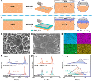
Since lithium-ion batteries (LIBs) were successfully commercialized by Sony, LIBs have been widely used in mobile electronic devices, electric vehicles and stationary energy storage systems because of their long cycle life, low self-discharge and environmental friendliness.1–3 However, the energy density of state-of-the-art LIBs cannot satisfy the increasing demand of drivers, resulting in severe range anxiety. Lithium metal batteries (LMBs) are a promising candidate for next-generation rechargeable batteries due to their high energy density obtained by using metallic lithium as anode materials.4–6 Unfortunately, the notorious Li dendrite growth and flammable organic liquid electrolytes are unavoidable results in severe and sporadic safety concerns.7–9 Therefore, unique technologies for higher energy density and safer LMBs are being urgently explored.10,11Solid-state electrolytes (SSEs) that can effectively mitigate unreliable safety have emerged as the advancement of science and technology.12,13 In recent years, a variety of SSEs have been explored, such as sodium superionic conductors,14 sulfides,15,16 perovskites17 and garnets.18,19 Among them, the garnet-type Li6.75La3Zr1.75Ta0.25O12 (LLZTO) attracts more attention because of its high ionic conductivity and chemical stability against Li metal.20–22 Unfortunately, LLZTO has poor wettability on lithium metal, which can lead to point-to-point contact at the interface (Fig. 1a). The point-to-point contact not only increases interfacial resistance but also results in locally uneven Li deposition.23,24 Therefore, interfacial buffer layers have been proposed to improve the surface wettability of LLZTO to Li metal.25–27
According to the different conductive carriers, the interfacial buffer layers can be divided into three types: electronic conductive, ionic conductive, and mixed conductive buffer layers.28–30 Currently, Al,31 Au,32 Zn,33 Sn,34 Ge35 and Sb18 have been reported as electronic conductive buffer layers. Undoubtedly, the electronic conductive buffer layer improves interfacial wettability, but electrons can easily pass through the buffer layer and combine with lithium ions.36–38 Especially in the case of high current density, lithium ions move slowly in solid-state electrolytes, and the rapid passage of electrons through the buffer layer generates an uneven electric field, resulting in the formation of dendrites along grain boundaries.39 Compared with the electron conductive buffer layer, the ionic conductive buffer layer can effectively block the attack of electrons on the garnet.40 In general, the ionic conductive buffer layer exhibits an obvious overpotential increase during the cycle, which is caused by high interface impedance.41,42 In conclusion, the microstructure and wettability of the lithium/garnet interface can be improved by the construction of the lithium alloy phase. However, the high electrical conductivity of the alloy interface layer causes the lithium dendrites to penetrate the solid electrolyte. Although the use of ionic conductive layers alone can prevent the destruction of electrons during lithium deposition, the electrical insulation characteristics increase the impedance between lithium metal and the solid electrolyte, which increases the overpotential during the cycle and causes battery failure. Therefore, it is difficult for ionic or electronic conduction alone to maintain a long-term stable cycle, and a mixed ion/electron conductive layer is a promising option.43–48 Taking Cu3N as an example, a mixed conductive layer Li3N–Cu was prepared in situ on the LLZTO surface by the reaction of Cu3N with Li metal.46 Li3N plays a role in conducting Li+, and Cu nanoparticles can uniformly disperse the electric field in the mixed conductive layer, thereby inhibiting the nucleation of Li dendrites. However, the mixed buffer layer is mainly prepared by magnetron sputtering, which increases the difficulty of experimental operation and the cost of production. Therefore, it is necessary to find a fast, simple and low-cost method to prepare a mixed interface buffer layer, which is helpful to realize the industrialization of solid-state lithium metal batteries.
Herein, a simple method is proposed for the construction of a mixed LiI/ZnLix ion/electron-conductive layer on LLZTO surface by an in situ reaction of ZnI2 film and molten Li metal (Fig. 1b). The mixed LiI/ZnLix layer enhances the interaction between Li metal and LLZTO. As a result, the cell with the LiI/ZnLix buffer layer shows a lower interfacial impedance of 10.3 Ω cm2 compared with the cell with bare LLZTO (1173.4 Ω cm2). The high Li+/e− conductivity of the mixed layer promotes Li+ transportation and Li nucleation, inhibiting the growth of Li dendrites along grain boundaries. Meanwhile, the simulation results show a much more uniform distribution of electric field and current density at the surface of the LiI/ZnLix buffer layer than that of bare LLZTO. As a proof, symmetrical cells with the LiI/ZnLix buffer layer exhibit stable plating/stripping performance of 2000 h at a low current density/capacity of 0.1 mA cm−2/0.1 mA h cm−2 and 800 h at a high current density/capacity of 1.0 mA cm−2/1.0 mA h cm−2. Moreover, the potential of the practical application of the LiI/ZnLix buffer layer for high-performance solid-state Li metal batteries is also demonstrated.
Results and discussion
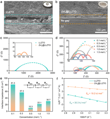
LLZTO was prepared by the solid reaction method.49 The X-ray diffraction results reveal that the synthesized LLZTO is a pure cubic garnet phase (Fig. S1†). As shown in Fig. 1c, the LLZTO pellet with high relative density (94.09%) is composed of generous crystalline LLZTO particles with smooth surfaces. ZnI2@LLZTO pellets were prepared by placing the bare LLZTO pellets in ZnI2 solution for 10 seconds (Fig. S2†). After soaking in 0.1 mol per L ZnI2 solution, the surface of LLZTO becomes rough, but the boundary of each crystal particle is still clear (Fig. S3†). When the concentration of ZnI2 is 0.5 mol L−1, the surface of LLZTO is uniformly covered by the ZnI2 buffer layer (Fig. 1d). Noticeably, obvious ZnI2 particles appear on the surface of LLZTO when the concentration of ZnI2 increases to 1.0 and 1.5 mol L−1. Meanwhile, the elemental mappings of ZnI2@LLZTO-0.5 disclose the uniform distribution of Zn, I, Zr and Ta elements (Fig. 1e). The Raman spectra of the bare LLZTO surface and the LLZTO treated with different concentrations of ZnI2 solution were compared (Fig. S4†). The peak at 140 cm−1 is the typical characteristic peak of ZnI2. The intensity of this characteristic peak increases with the increase of ZnI2 concentration. When the concentration of ZnI2 exceeds 1 mol L−1, the characteristic peak becomes obvious. The Raman peaks belonging to LLZTO show no change in any sample. Due to the relatively low content of ZnI2 on the LLZTO surface, the reaction between Li metal and ZnI2 cannot be directly observed. To verify the above reaction, a large amount of ZnI2 powder was added to the molten Li metal, and they underwent a violent reaction (Fig. S5†). XRD test was performed on the product after the reaction, and the (111) diffraction peak of LiI was clearly observed (Fig. S6†). The above experiment proves that our idea can be realized. Subsequently, the mixed conductive buffer layers were prepared in situ by the reaction of molten Li metal with ZnI2 thin film on the surface of LLZTO. To determine the composition of the interface buffer layer on the LLZTO surface, the detailed Zn, I, and Li species at the interfaces were investigated by XPS. The initial peak position of Zn 2p spectra is 1045.0 and 1022.1 eV.33 After the reaction, the peak position is shifted to 1044.2 and 1021.3 eV due to the formation of the Zn–Li bond, indicating the formation of ZnLix alloy (Fig. 1f). Meanwhile, analogous variation is also observed in I 3d XPS spectra (Fig. 1g). In Li 1s spectra, two new peaks appear after the reaction, corresponding to the formation of the ZnLix alloy at 56.4 eV and LiI at 55.4 eV, respectively (Fig. 1h). In addition, we also provided XPS spectra of oxygen element (Fig. S7†). The peak position of O 1s before and after the reaction was 531.4 eV, without any change. This indicates that the reaction at the interface only involves ZnI2 and Li metal.Subsequently, we visually observed the interfacial wettability of LLZTO with or without the ZnI2 buffer layer. A liquid Li droplet appears spherical on the bare LLZTO surface (inset in Fig. 2a). In addition, the cross-sectional SEM image shows a significant gap at the Li/LLZTO interface (Fig. 2a), which leads to high interfacial resistance and uneven interfacial electric field. In contrast, ZnI2@LLZTO has excellent lithiophilic properties, and the Li metal spreads evenly on the SSE surface (inset in Fig. 2b). The SEM image clearly shows that the Li/ZnI2@LLZTO interface is compact and seamless (Fig. 2b). To further verify the effect of the buffer layer on interface impedance, Li/SSE/Li symmetric cells were assembled. Fig. 2c shows the EIS data for the Li/SSE/Li cells at room temperature. The cell with bare LLZTO presents a large semicircle in the Nyquist plots, which means a high interfacial resistance (1173.4 Ω cm2). In contrast, the interfacial impedance of Li/ZnI2@LLZTO/Li drops substantially to 10.3 Ω cm2. The result indicates that the ZnI2 buffer layer can effectively reduce the interface impedance, which is beneficial for the benign electrochemical reaction at the interface. Furthermore, the interface impedances of Li/ZnI2@LLZTO/Li cells with different concentrations of ZnI2 were compared (Fig. 2d and e). When the concentration of ZnI2 is 0.5 mol L−1, the interface impedance is the lowest. The possible reasons for this result are as follows: (i) when the concentration of ZnI2 is low (<0.5 mol L−1), the surface of LLZTO cannot be completely covered by ZnI2, which hardly achieves the best effect of improving the interface; (ii) the ZnI2 buffer layer on the surface of LLZTO is too thick to hinder the migration of Li+ at a high concentration of ZnI2 (>1.0 mol L−1).
In order to further select the optimal concentration, we assembled symmetrical cells on solid electrolytes treated with different concentrations of ZnI2 solution for the galvanostatic charge–discharge test. As shown in Fig. S8,† when the concentration of ZnI2 is 0.5 mol L−1, the polarization voltage of the symmetric cell is the smallest (only 13 mV). The results of impedance and galvanostatic charge–discharge show that 0.5 mol L−1 is the best concentration. Based on the above experimental results, ZnI2@LLZTO-0.5 is selected as the research object in this work. In addition, the interfacial activation energies (Ea) of Li/LLZTO and Li/ZnI2@LLZTO were obtained through variable temperature tests (Fig. S9†). The Ea of the Li/LLZTO interface is 30.3 kJ mol−1, whereas that of the Li/ZnI2@LLZTO interface is only 19.2 kJ mol−1 (Fig. 2f). Therefore, LiI and ZnLix alloy buffer layer formed in situ by the reaction of ZnI2 and Li metal can effectively reduce the impedance and promote the Li+ migration at the interface.
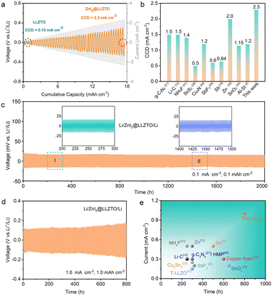
The superiority of SSE with a buffer layer to suppress Li dendrites was evaluated by the critical current density (CCD). As shown in Fig. 3a, the Li/LLZTO/Li cell experiences a short circuit at a current density of 0.15 mA cm−2, indicating that point contact at the interface can enhance the local electric field, leading to a “tip effect” and inducing Li dendrites to penetrate the SSE. In contrast, the CCD of the Li/ZnI2@LLZTO/Li cell reaches 2.3 mA cm−2 due to the presence of the ZnI2 buffer layer. Fig. S10† shows the CCD curve of a symmetrical cell with a ZnI2 concentration of 1.5 mol L−1. When the current density increased to 1 mA cm−2, the cell experienced a soft short-circuit. This result is consistent with the impedance test, indicating that the thickness of the buffer layer has a significant impact on battery performance. Noticeably, this work is superior to the reported methods for modifying the LLZTO interface (Fig. 3b).2,12,18,21,28,29,33,41,43,46 This may be because the good affinity of LiI to LLZTO as well as the good lithiophilicity of the ZnLix alloy to Li metal is better than that of the buffer layer which only has an affinity for single LLZTO or Li metal.50 To verify this inference, the Li/SSE/Li symmetric cell with I2 as the buffer layer was assembled. The CCD of the Li/SSE/Li cell with the I2 buffer layer is 0.5 mA cm−2 (Fig. S11†), which is lower than the 2.3 mA cm−2 of the mixed LiI/ZnLix buffer layer.
More importantly, the Li/ZnI2@LLZTO/Li symmetric cells also present excellent long-term cycling ability. As shown in Fig. 3c, the Li/ZnI2@LLZTO/Li cell delivers a stable cycle for 2000 h with an overpotential of only 13 mV at a current density of 0.1 mA cm−2 and an area capacity of 0.1 mA h cm−2. In contrast, the Li/LLZTO/Li cell exhibits a large overpotential, and the voltage rapidly decreases after 25 h, indicating a short circuit (Fig. S12†). Even under 0.5 mA cm−2 to 0.5 mA h cm−2 and 1.0 mA cm−2 to 1.0 mA h cm−2 conditions, the symmetrical cells with the ZnI2 interface buffer layer can stably cycle for 1600 and 800 h, respectively (Fig. 3d and S13†). The electrochemical performance is better than that of most of the reported Li/SSE/Li cells (Fig. 3e, S14 and Table S1†).3,12,17,21,22,24,25,29,33,34,41,43,45,48 In general, most reported Li/garnet/Li cells operate at low current density with short cycle life. The above results further demonstrate that the mixed conductive buffer layers are superior to a single electronic or ionic conductive buffer layer.51,52
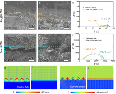
In order to further confirm the influence of the ZnI2 buffer layer on the interface stability, SEM and EIS were performed on the cells after 200 h (100 cycles). As shown in Fig. 4a and b, the Li metal still maintains close contact with the ZnI2@LLZTO, without gaps or lithium dendrites. Compared with the initial state, the interface impedance increases by only 3.2 Ω cm2 (Fig. 4c), which indicates that the buffer layer plays a bridging role and effectively promotes the Li+ migration at the interface. In contrast, Li/LLZTO/Li shows more obvious cracks with loose Li dendrites at the interface after cycling (Fig. 4d and e). Poor interface contact leads to large interface impedance, which is also the root cause of battery failure (Fig. 4f). It's worth noting that the interface of Li metal and LLZTO is still in close contact in the symmetrical cell with the ZnI2 buffer layer even at high current density and capacity (1.0 mA cm−2 and 1.0 mA h cm−2) (Fig. S15†). Moreover, the interfacial impedance of the symmetric cell increases by only 7.3 Ω cm2. The results prove that the LiI/ZnLix mixed layer plays a crucial role in stabilizing the interface.
Subsequently, the electric field distribution and current density of the Li/SSE interface were simulated by COMSOL Multiphysics to further investigate the effect of the ZnI2 buffer layer on Li dendrite growth. Because Li metal and bare LLZTO are in point contact at the interface, the electric field strength and current density at the contact point are much greater than those at non-contact locations (Fig. 4g and i). This causes Li+ in the bare LLZTO to aggregate and deposit at the contact point, which is also the reason for large polarization and dendrite formation. For the Li/ZnI2@LLZTO interface, because of the uniform distribution of Li metal on the LLZTO surface, the electric field and current density at the interface are evenly distributed (Fig. 4h and j). The transmission and diffusion of lithium ions at the interface are very smooth, resulting in small interface impedance and excellent electrochemical performance of symmetrical cells.
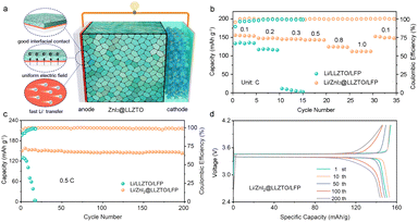
The Li/ZnI2@LLZTO/LFP full cell was assembled to demonstrate the potential of the practical application of the ZnI2 buffer layer (Fig. 5a). The Li/ZnI2@LLZTO/LFP full cell shows an excellent rate performance, which hands over the specific discharge capacities of 155.8, 147.6, 145.1, 143.7, 124.4, and 112.0 mA h g−1 at 0.1, 0.2, 0.3, 0.5, 0.8, and 1.0C, respectively (Fig. 5b). When the current goes back to 0.1C, the discharge capacity can recover to 152.5 mA h g−1, indicating significant reversibility. In contrast, as the current increases, the full cell assembled with bare LLZTO exhibits critical capacity degradation. The excellent rate performance of full cells with ZnI2 is attributed to the smooth transfer of Li+ at the interface. In addition, the full cell with bare LLZTO shows poor long-term performance (Fig. 5c). By comparison, the full cell with ZnI2@LLZTO displays a discharge capacity of 143.9 mA h g−1 with high coulombic efficiency (99%) after 200 cycles. In particular, the capacity loss per cycle is only 0.021%. As shown in Fig. 5d, the smooth charge–discharge profiles suggest that the Li+ transmission in the full cell is rapid and uniform. More importantly, the electrochemical performance is better than that of most of the full cells reported in the literature (Fig. S16†).
Conclusions
In summary, we constructed a mixed LiI/ZnLix ion/electron-conductive layer on an LLZTO surface by in situ reaction of ZnI2 film and molten Li metal. The mixed LiI/ZnLix layer enhances the interaction between Li metal and LLZTO, resulting in a low interfacial impedance of 10.3 Ω cm2. The mixed conductive layer regulates the electric field at the interface, which ensures a uniform Li deposition and inhibits the formation of Li dendrites. As a result, the symmetric cells exhibit a long cycle life of 800 h at 1.0 mA cm−2 and 1.0 mA h cm−2. Moreover, the full cells show excellent cycling performance with a capacity of 143.9 mA h g−1 after 200 cycles and the capacity loss per cycle is only 0.021%. This simple modification strategy provides a good prospect for the design of solid-state Li metal batteries based on garnets.Data availability
All experimental data is provided in the ESI.†Author contributions
J. S. and L. L. proposed the concept and supervised the work; L. Z. and J. W. designed the experiments and wrote the paper; X. Z. helped to analyze the data; X. Z. and F. J. helped to summarize the data and supervised the research; all authors discussed the results and revised the manuscript. All authors have approved the final version of the manuscript.Conflicts of interest
There are no conflicts to declare.Acknowledgements
This work was supported by the National Natural Science Foundation of China (22209140, 52202286, 52072328), Natural Science Foundation of Shandong Province (ZR2022QE059), Natural Science Foundation of Zhejiang Province (LZ21E010001), Shandong Laboratory of Advanced Materials and Green Manufacturing at Yantai (Yantai) (AMGM2023A08).Notes and references
- D. Liu, Z. Bai, M. Li, A. Yu, D. Luo, W. Liu, L. Yang, J. Lu, K. Amine and Z. Chen, Chem. Soc. Rev., 2020, 49, 5407–5445 RSC.
- L. Zhai, K. Yang, F. Jiang, W. Liu, Z. Yan and J. Sun, J. Energy Chem., 2023, 79, 357–364 CrossRef CAS.
- J. Cui, S. Yao, A. Guerfi, C. Kim, J. B. Goodenough and H. Khani, Energy Storage Mater., 2022, 53, 899–908 CrossRef.
- B. Liu, J. Zhang and W. Xu, Joule, 2018, 2, 833–845 CrossRef CAS.
- Y. Yin, J. Yang, J. Luo, G. Lu, Z. Huang, J. Wang, P. Li, F. Li, Y. Wu, T. Tian, Y. Meng, H. Mo, Y. Song, J. Yang, L. Feng, T. Ma, W. Wen, K. Gong, L. Wang, H. Ju, Y. Xiao, Z. Li, X. Tao and H. Yao, Nature, 2023, 616, 77–83 CrossRef CAS PubMed.
- J. Wang, R. Chen, L. Yang, M. Zan, P. Chen, Y. Li, W. Li, H. Yu, X. Yu, X. Huang, L. Chen and H. Li, Adv. Mater., 2022, 34, 2200655 CrossRef CAS PubMed.
- W. Wu, Z. Song, Y. Dai, X. Zheng, G. Chai, J. Yang and W. Luo, Adv. Energy Mater., 2022, 12, 2200999 CrossRef CAS.
- K. Yan, Z. Lu, H. Lee, F. Xiong, P. Hsu, Y. Li, J. Zhao, S. Chu and Y. Cui, Nat. Energy, 2016, 1, 16010 CrossRef CAS.
- Y. Liu, X. Tao, Y. Wang, C. Jiang, C. Ma, O. Sheng, G. Lu and X. Lou, Science, 2022, 375, 739–745 CrossRef CAS PubMed.
- C. Yu, F. Zhao, J. Luo, L. Zhang and X. Sun, Nano Energy, 2021, 83, 105858 CrossRef CAS.
- W. Luo, Y. Gong, Y. Zhu, K. K. Fu, J. Dai, S. D. Lacey, C. Wang, B. Liu, X. Han, Y. Mo, E. D. Wachsman and L. Hu, J. Am. Chem. Soc., 2016, 138, 12258–12262 CrossRef CAS PubMed.
- J. Duan, W. Wu, A. M. Nolan, T. Wang, J. Wen, C. Hu, Y. Mo, W. Luo and Y. Huang, Adv. Mater., 2019, 31, 1807243 CrossRef PubMed.
- X. Liang, Q. Pang, I. R. Kochetkov, M. S. Sempere, H. Huang, X. Sun and L. F. Nazar, Nat. Energy, 2017, 2, 17119 CrossRef CAS.
- Y. Xiao, K. Jun, Y. Wang, L. J. Miara, Q. Tu and G. Ceder, Adv. Energy Mater., 2021, 11, 2101437 CrossRef CAS.
- Y. Jin, K. Liu, J. Lang, X. Jiang, Z. Zheng, Q. Su, Z. Huang, Y. Long, C. Wang, H. Wu and Y. Cui, Joule, 2019, 3, 1–13 CrossRef.
- C. Duan, Z. Cheng, W. Li, F. Li, H. Liu, J. Yang, G. Hou, P. He and H. Zhou, Energy Environ. Sci., 2022, 15, 3236–3245 RSC.
- J. Gao, J. Zhu, X. Li, J. Li, X. Guo, H. Li and W. Zhou, Adv. Funct. Mater., 2021, 31, 2001918 CrossRef CAS.
- R. Dubey, J. Sastre, C. Cancellieri, F. Okur, A. Forster, L. Pompizii, A. Priebe, Y. Romanyuk, L. Jeurgens, M. Kovalenko and K. Kravchyk, Adv. Energy Mater., 2021, 11, 2102086 CrossRef CAS.
- L. Fan, S. Wei, S. Li, Q. Li and Y. Lu, Adv. Energy Mater., 2018, 8, 1702657 CrossRef.
- T. Jiang, P. He, G. Wang, Y. Shen, C. Nan and L. Fan, Adv. Energy Mater., 2020, 10, 1903376 CrossRef CAS.
- Y. Huang, B. Chen, J. Duan, F. Yang, T. Wang, Z. Wang, W. Yang, C. Hu, W. Luo and Y. Huang, Angew. Chem., Int. Ed., 2020, 59, 3699–3704 CrossRef CAS PubMed.
- P. Srivastava, Y. K. Liao, K. Iputera, S. F. Hu and R. S. Liu, ChemSusChem, 2023, 16, e202300504 CrossRef CAS PubMed.
- W. Feng, X. Dong, Z. Lai, X. Zhang, Y. Wang, C. Wang, J. Luo and Y. Xia, ACS Energy Lett., 2019, 4, 1725–1731 CrossRef CAS.
- Y. Jin, K. Liu, J. Lang, D. Zhuo, Z. Huang, C. Wang, H. Wu and Y. Cui, Nat. Energy, 2018, 3, 732 CrossRef CAS.
- J. Duan, L. Huang, T. Wang, Y. Huang, H. Fu, W. Wu, W. Luo and Y. Huang, Adv. Funct. Mater., 2020, 30, 1908701 CrossRef CAS.
- H. Zheng, G. Li, R. Ouyang, Y. Han, H. Zhu, Y. Wu, X. Huang, H. Liu and H. Duan, Adv. Funct. Mater., 2022, 32, 2205778 CrossRef CAS.
- Y. Zhong, Y. Xie, S. Hwang, Q. Wang, J. J. Cha, D. Su and H. Wang, Angew. Chem., Int. Ed., 2020, 59, 14003–14008 CrossRef CAS PubMed.
- B. Zhao, W. Ma, B. Li, X. Hu, S. Lu, X. Liu, Y. Jiang and J. Zhang, Nano Energy, 2022, 91, 106643 CrossRef CAS.
- A. Wang, J. Li, M. Yi, Y. Xie, S. Chang, H. Shi, L. Zhang, M. Bai, Y. Zhou, Y. Lai and Z. Zhang, Energy Storage Mater., 2022, 49, 246–254 CrossRef.
- W. Huang, N. Zhao, Z. Bi, C. Shi, X. Guo, L. Fan and C. Nan, Mater. Today Nano, 2020, 10, 100075 CrossRef.
- K. Fu, Y. Gong, B. Liu, Y. Zhu, S. Xu, Y. Yao, W. Luo, C. Wang, S. D. Lacey, J. Dai, Y. Chen, Y. Mo, E. Wachsman and L. Hu, Sci. Adv., 2017, 3, e1601659 CrossRef PubMed.
- N. Zhao, R. Fang, M. He, C. Chen, Y. Li, Z. Bi and X. Guo, Rare Met., 2018, 37, 473–479 CrossRef CAS.
- Z. Wan, K. Shi, Y. Huang, L. Yang, Q. Yun, L. Chen, F. Ren, F. Kang and Y. He, J. Power Sources, 2021, 505, 230062 CrossRef CAS.
- M. He, Z. Cui, C. Chen, Y. Li and X. Guo, J. Mater. Chem. A, 2018, 6, 11463–11470 RSC.
- W. Luo, Y. Gong, Y. Zhu, Y. Li, Y. Yao, Y. Zhang, K. Fu, G. Pastel, C. Lin, Y. Mo, E. D. Wachsman and L. Hu, Adv. Mater., 2017, 29, 1606042 CrossRef PubMed.
- Y. Guo, S. Wu, Y. He, F. Kang, L. Chen, H. Li and Q. Yang, eScience, 2022, 2, 138–163 CrossRef.
- W. Feng, X. Dong, X. Zhang, Z. Lai, P. Li, C. Wang, Y. Wang and Y. Xia, Angew. Chem., Int. Ed., 2020, 132, 5384–5387 CrossRef.
- Q. Pang, X. Liang, I. R. Kochetkov, P. Hartmann and L. Nazar, Angew. Chem., Int. Ed., 2018, 130, 9943–9946 CrossRef.
- Y. Lee, S. Fujiki, C. Jung, N. Suzuki, N. Yashiro, R. Omoda, D. Ko, T. Shiratsuchi, T. Sugimoto, S. Ryu, J. Ku, T. Watanabe, Y. Park, Y. Aihara, D. Im and I. Han, Nat. Energy, 2020, 5, 299–308 CrossRef CAS.
- X. Ji, S. Hou, P. Wang, X. He, N. Piao, J. Chen, X. Fan and C. Wang, Adv. Mater., 2020, 32, 2002741 CrossRef CAS PubMed.
- H. Duan, W. Chen, M. Fan, W. Wang, L. Yu, S. Tan, X. Chen, Q. Zhang, S. Xin, L. Wan and Y. Guo, Angew. Chem., Int. Ed., 2020, 59, 12069–12075 CrossRef CAS PubMed.
- G. V. Alexander, C. Shi, J. O'Neill and E. Wachsman, Nat. Mater., 2023, 22, 1136 CrossRef CAS PubMed.
- Y. Chen, M. He, N. Zhao, J. Fu, H. Huo, T. Zhang, Y. Li, F. Xu and X. Guo, J. Power Sources, 2019, 420, 15–21 CrossRef CAS.
- H. Huo, Y. Chen, R. Li, N. Zhao, J. Luo, J. G. Pereira da Silva, R. Mücke, P. Kaghazchi, X. Guo and X. Sun, Energy Environ. Sci., 2020, 13, 127–134 RSC.
- Z. Qin, Y. Xie, X. Meng, D. Qian, C. Shan, D. Mao, G. He, Z. Zheng, L. Wan and Y. Huang, Chem. Eng. J., 2022, 447, 137538 CrossRef CAS.
- Q. Ma, X. Zhang, A. Wang, Y. Xia, X. Liu and J. Luo, Adv. Funct. Mater., 2020, 30, 2002824 CrossRef CAS.
- J. Fu, P. Yu, N. Zhang, G. Ren, S. Zheng, W. Huang, X. Long, H. Li and X. Liu, Energy Environ. Sci., 2019, 12, 1404–1412 RSC.
- T. Wang, J. Duan, B. Zhang, W. Luo, X. Ji, H. Xu, Y. Huang, L. Huang, Z. Song, J. Wen, C. Wang, Y. Huang and J. B. Goodenough, Energy Environ. Sci., 2022, 15, 1325–1333 RSC.
- Z. Zhao, Z. Wen, X. Liu, H. Yang, S. Chen, C. Li, H. Lv, F. Wu, B. Wu and D. Mu, Chem. Eng. J., 2021, 405, 127031 CrossRef CAS.
- S. Gao, P. Ju, Z. Liu, L. Zhai, W. Liu, X. Zhang, Y. Zhou, C. Dong, F. Jiang and J. Sun, J. Energy Chem., 2022, 69, 356–362 CrossRef CAS.
- Z. Lu, Z. Yang, C. Li, K. Wang, J. Han, P. Tong, G. Li, B. Vishnugopi, P. Mukherjee, C. Yang and W. Li, Adv. Energy Mater., 2021, 11, 2003811 CrossRef CAS.
- X. Liu, R. Garcia-Mendez, A. Lupini, Y. Cheng, Z. Hood, F. Han, A. Sharafi, J. Idrobo, N. Dudney, C. Wang, C. Ma, J. Sakamoto and M. Chi, Nat. Mater., 2021, 20, 1485–1490 CrossRef CAS PubMed.
Footnote |
| † Electronic supplementary information (ESI) available. See DOI: https://doi.org/10.1039/d4sc00786g |
| This journal is © The Royal Society of Chemistry 2024 |

