DOI:
10.1039/D4SC01391C
(Edge Article)
Chem. Sci., 2024,
15, 8404-8413
An unprecedented roll-off ratio in high-performing red TADF OLED emitters featuring 2,3-indole-annulated naphthalene imide and auxiliary donors†
Received
28th February 2024
, Accepted 29th April 2024
First published on 2nd May 2024
Abstract
The capability of organic emitters to harvest triplet excitons via a thermally activated delayed fluorescence (TADF) process has opened a new era in organic optoelectronics. Nevertheless, low brightness, and consequently an insufficient roll-off ratio, constitutes a bottleneck for their practical applications in the domain of organic light-emitting diodes (OLEDs). To address this formidable challenge, we developed a new design of desymmetrized naphthalimide (NMI) featuring an annulated indole with a set of auxiliary donors on its periphery. Their perpendicular arrangement led to minimized HOMO–LUMO overlap, resulting in a low energy gap (ΔEST = 0.05–0.015 eV) and efficient TADF emission with a photoluminescence quantum yield (PLQY) ranging from 82.8% to 95.3%. Notably, the entire set of dyes (NMI-Ind-TBCBz, NMI-Ind-DMAc, NMI-Ind-PXZ, and NMI-Ind-PTZ) was utilized to fabricate TADF OLED devices, exhibiting yellow to red electroluminescence. Among them, red-emissive NMI-Ind-PTZ, containing phenothiazine as an electron-rich component, revealed predominant performance with a maximum external quantum efficiency (EQE) of 23.6%, accompanied by a persistent luminance of 38![[thin space (1/6-em)]](https://www.rsc.org/images/entities/char_2009.gif) 000 cd m−2. This results in a unique roll-off ratio (EQE10 000 = 21.6%), delineating a straightforward path for their commercial use in lighting and display technologies.
000 cd m−2. This results in a unique roll-off ratio (EQE10 000 = 21.6%), delineating a straightforward path for their commercial use in lighting and display technologies.
Introduction
Along with the miniaturization of electronic components,1–4 there is a growing demand for the rapid advancement of organic photonics dedicated to novel lighting and display technologies.5–8 Since 2012,9,10 when Adachi and co-workers revived the phenomenon of thermally activated delayed fluorescence (TADF) for organic emitters, immense research interest has emerged in new molecular design strategies to increase TADF emission efficiency and demonstrate its practical utility for a new generation of organic light-emitting diodes (OLEDs).8 In this regard, a small energy splitting (ΔEST) between their singlet (S1) and triplet (T1) excited states, allowing them to harvest all the electrically generated singlet and triplet excitons, must be induced to trigger effective reverse intersystem crossing (RISC) which is an endothermal process. From the molecular point of view, this is translated to a minimal overlap between their frontier molecular orbitals (FMOs) and is practically performed for small-molecule emitters, whose structures typically consist of rigid, π-electron platforms linked or fused with acceptor (A) units.7,11 The latter ones, are, in turn, through-bond conjugated with highly twisted electron-donating (D) units that enable a significant impact on CT characteristics. In this regard, aromatic imides12 proved to be perfectly suited TADF molecular platforms because of their photoelectric attributes, well-defined LUMO energies, and propensity to undergo synthetic modifications to enable the decoration of the framework with various electron-rich moieties. Along this line, Chen and co-workers13 reported a N-phenylphthalimide decorated with 4-, 5-carbazoles (AI-Cz, see Fig. 1a) to adopt a highly twisted form which entails a small ΔEST value of 0.06 eV, leading to a yellow TADF emitter with an EQEmax 23.2%. With a small structural extension towards a biphenyl-based platform (Fig. 1a), Bin and You14 benefitted from the containment of highly twisted heptagonal imide acceptors decorated with two dimethylacridines (DMAc-BPI). This permits the reduction of excessive intramolecular rotation, making it a remarkable non-doped green TADF OLED emitter with EQEmax 24.7%. With a similar arrangement of DMAc moieties aimed at inhibiting close π–π stacking and adopting a more planar and rigid conformation, Bin and colleagues introduced a phenanthrene-embedded emitter.15 This, featuring a pyrazine- and maleimide-fused electron-accepting moiety (P-DMAC-BPyM, Fig. 1a), proved to act as an orange emitter with an EQEmax of 26%. Meanwhile, Wu and Yang16 turned their attention to an NMI scaffold with a spirobiphenyl analogue mounted in the 4-position dihydroacridine (NAI-DPAc, Fig. 1b). Such a bent and sterically hindered structure of the donor induced fast RISC transition and thus efficient orange TADF emission (EQEmax of 29.2%). The parental core was employed a second time by the group with a donor of enlarged bulk, which was fused with a benzothiophene moiety (BFDMAc-PhNAI).17,18 Surprisingly, this compound showed weaker TADF emission than NAI-DPAc, as demonstrated in Fig. 1b. Very recently, our group has demonstrated a pair of emitters consisting of an NMI scaffold with varying degrees of conjugation.19 Specifically, 4-TBCz-NMI served as the TADF dopant, while its analogue with a thoroughly fused TBCz moiety (via C–N/C–C bonds) served as the fluorescent dopant. This structural affinity provided a perfect match in excited state energies to ensure efficient Förster resonance energy transfer (FRET) which resulted in a yellow narrowband hyperfluorescent emission (FWHM = 40 nm) in an OLED with an EQE of 26%. While TADF emitters based on aromatic imides have shown remarkable progress in boosting EQEmax for OLED devices, they exhibit a substantial roll-off ratio similar to most existing TADF emitters. This phenomenon refers to the decrease in efficiency with increasing luminance (brightness) and poses a major challenge to OLED technology, limiting their commercial applications. Given that various factors contribute to roll-off, including carrier trapping, exciton quenching, and voltage droop, there is a constant demand to develop new emitter structures that allow for a trade-off between persistent EQE and high luminance which are, however, extremely scarce.20
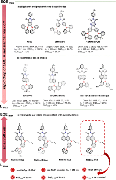 |
| | Fig. 1 Current progress in the application of aromatic imides (a and b) as green, yellow, and orange TADF OLED emitters with respect to their electroluminescence efficiency, brightness, and roll-off; (c) the new approach with superior trade-off between EQE and brightness to provide a greatly reduced roll-off ratio. | |
Thus, to tackle this vital challenge, we herein report a high-performance and persistent red-TADF emitter design strategy by annulation of an NMI scaffold in positions 3- and 4- with indole having a set of twisted electron-rich substituents at its periphery (NMI-Ind-TBCz, NMI-Ind-DMAc, NMI-Ind-PXZ, and NMI-Ind-PTZ), as demonstrated in Fig. 1c. The asymmetric annulation of D–A units allows for the spatial separation of the HOMO–LUMO levels (see ESI, Fig. 55†), whereas perpendicularly oriented auxiliary donors lead to a significantly reduced ΔEST energy splitting (0.05–0.15 eV) and minimized π–π interaction to hinder the probability of non-radiative decay. Hence, the best-performing TADF dye in the series (NMI-Ind-PTZ) not only exhibits a pronounced PLQY of 95.3% but also demonstrates maximum electroluminescence performance in fabricated red-emitting OLED devices as high as 23.6%, and luminance retained at 10![[thin space (1/6-em)]](https://www.rsc.org/images/entities/char_2009.gif) 000 cd m−2 with an EQE of 21.6%. This output indicates an unprecedented roll-off ratio and greatly improved operational stability, unlocking the full potential of OLED applications for red TADF emitters.
000 cd m−2 with an EQE of 21.6%. This output indicates an unprecedented roll-off ratio and greatly improved operational stability, unlocking the full potential of OLED applications for red TADF emitters.
Results and discussion
Despite exhibiting excellent photoluminescence quantum yields (PLQYs)19 and a distinct modular near-infrared (NIR) emission shift,21 NMI dyes, previously reported by our group, lacked TADF characteristics. The inability of these molecules to harvest triplet excitones, stemmed, arguably, from the insufficient separation of electron-rich and -deficient components. Hence, our new molecular design capitalizes on the annulation of the NMI core at lateral positions (3, 4) with indole, which is equipped with an auxiliary electron-donating species that has never been explored in the field of OLED emitters. Such a structural perturbation is anticipated to yield distinguished optoelectronic properties as the fully conjugated D–A scaffold with, this time, precisely separated HOMO–LUMO levels is supposed to permit remarkable PLQY. On the other hand, the annulation of a 5-membered ring (in a “desymmetrized” manner) provides a point of departure for facile straightforward functionalization with various electron-donating groups, so to give a warranty of strong C–T characteristics which is in striking difference to previously discussed symmetrical D–A structures. Moreover, the affinity of naphthalene in conjunction with the bulkiness of D moieties was envisioned to enforce its desired, perpendicular orientation, which can in turn lead to a tight interaction between adjacent molecules in a crystalline network, with severely limited participation of π-interactions promoting radiative deactivation pathways. Building on those assumptions, our attention was turned to the synthesis of dyes 6a–d which was elaborated through six concise and scalable synthetic steps, as demonstrated in Scheme 1 (for the detailed procedures, see the ESI†). Starting imide 1 was first synthesized from commercially available 2,4,6-trimethylaniline and 4-bromo-1,8-naphthalic anhydride under common acidic conditions. Afterwards, 1 was subjected to Suzuki cross-coupling with 2-nitro phenylboronic acid leading almost quantitatively to intermediate 2. In the next step, a key Cadogan ring-closure reaction followed by alkylation of the fused indole resulted in 4 in a very good yield (76% and 98% respectively). Subsequently, selective bromination to the position 6 of fused indole (95%) led to carrying out the Buchwald–Hartwig reaction with the set of electron-rich moieties to deliver four D–D–A emitters 6a–d. All these compounds have been characterized and confirmed via mass spectrometry (MS) and nuclear magnetic resonance (NMR).
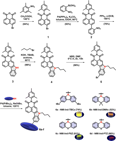 |
| | Scheme 1 The synthetic path towards “bow-like” TADF dyes 6a–d and their solid-state emission. | |
Crystallography
To investigate the trade-off between electronic character of the mounted substituent and their final molecular arrangement we aimed for thorough analyses in the crystalline phase. We were unable to obtain X-ray quality single crystals for dyes 6a and 6d, but to our delight, we could grow appropriate ones for compounds 5 (see ESI, Fig. 48†), 6b, and 6c by slow evaporation from their solution of ethyl acetate and chloroform respectively (Fig. 2a and d). Such analysis allowed us to gradually correlate the influence of bulky substituents on crystal engineering and their potential impact on photophysical behavior. Intuitively, the brominated precursor of NMI-Ind (5) appears to be flat with close C–H⋯π interplays of 3.74 Å between polarly oriented dimers (Fig. 48, ESI†). When it comes to DMAc and PXZ functionalized dyes (6b and 6c), they both crystallize in the monoclinic P21/c space groups; however, their mutual solid-state behavior is slightly different. Consecutively, four molecules of 6b were found per unit cell in antiparallel, mutual arrangement (see Fig. 2b). Closer view of the packing mode of 6b unveils an extended, regular 3D structure in the crystal lattice (Fig. 2c) maintained via two, very weak, lateral C–H⋯π interactions which were measured to be 4.38 Å (Fig. 2b). It is seen that the insertion of DMAc sustains a less twisted, perpendicular arrangement of DMAc (rotation inhibited as reflected in dihedral angle 91.60°, Fig. 2a) and thus, thoroughly alters the molecular arrangement of the entire molecule delivering, to our surprise, a concave/bend geometry. This is translated to the depth maximum, which was measured to be up to 1 Å (as shown in Fig. 47, ESI†). When it comes to 6c, four molecules per unit cell were found in which two adjacent entities show nearly perpendicular “head-to-head” orientation, conversely to the derivative containing DMAc (6b). This alignment (Fig. 2e) is stabilized by C–H⋯π interactions between the benzene ring of indole and the PHX benzene ring (3.38 Å). Closer inspection into the dihedral angle between indole and PXZ (99.34°, Fig. 2d) revealed that less pronounced conformation twist with respect to the noticed for 6b. Under these appearances, the structural arrangements identified in the solid-state seem sufficient to avoid aggregation by minimizing a determinantal π–π interaction and thus guarantee efficacious spatial separation of FMOs which is a premise for an efficient photon up conversion process.
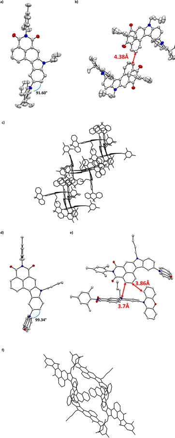 |
| | Fig. 2 Top views and side views of the crystal structure and space arrangement of 6b (a–c) and 6c (d–f). Colour code: gray – carbon; white – hydrogen; blue – nitrogen; red – oxygen. | |
Computational methods
In order to gain more insight into the optical and electronic properties of compounds 6a–6d, we modeled their excited states with the use of electronic structure calculations. For the sake of brevity, a detailed description of these calculations is provided in the ESI (Section S6).† Here, we recount only the most important results. In the calculations, each compound was represented by a truncated model, wherein the n-butyl group was replaced with a methyl group and the 2,4,6-trimethylphenyl group was replaced with a hydrogen atom. Additionally, the two tert-butyl groups of compound 6a were also replaced with hydrogen atoms. For reference, the electronic structures of the lowest few singlet and triplet states of compounds 6a–6d are visualized in Fig. 3a–d in the form of electron density difference maps (EDDMs). According to the output of our calculations (the vertical excitation spectra of compounds 6a–6d are summarized in Table 3 in the ESI†), each investigated compounds 6a–6d has two low-lying ππ*-type singlet excited states that are localized on the NMI-Ind moiety. In all cases, the lower ππ*-type of the two ππ*-type states shows a relatively low oscillator strength on the order of 0.1, while the oscillator strength of the higher ππ*-type is larger, at around 0.5. Accordingly, in what follows, we would denote the lower ππ*-type state as the dark state and the higher ππ*-type state as the bright state. Because the two states are closely spaced, their absorption will overlap with one another. The lowest photoabsorption band of each emitter would mainly arise from the bright, higher, ππ*-type state. Conversely, the fluorescence emission of each compound predominantly arises from the lower, dark, ππ*-type state. The electric dipole moment of the dark ππ*-type state is somewhat larger in magnitude than that of the ground state. This is in line with the fact that all five compounds are experimentally found to exhibit solvatofluorochromism: the maximum of the fluorescence emission band of each compound is redshifted with increasing solvent polarity (vide infra). Compounds 6b, 6c, and 6d also possess a low-energy intramolecular charge transfer (ICT) state, which corresponds to a shift of electron density from the donor moiety onto the NMI-Ind moiety (an analogous ICT state also exists in compound 6a, but it lies relatively higher in energy). The electronic structure calculations indicate that, for each compound in the series 6a–6d, the ICT state lies higher in energy than the lowest ππ*-type state. However, it must be borne in mind that the calculations pertain to the gas phase, a non-polar environment. We expect that, in a polar environment, the ICT state may be stabilized relative to the ππ*-type states to such an extent that it becomes the lowest singlet excited state (an example of state reversal). Under these conditions, the ICT state may give rise to appreciable fluorescence emission.
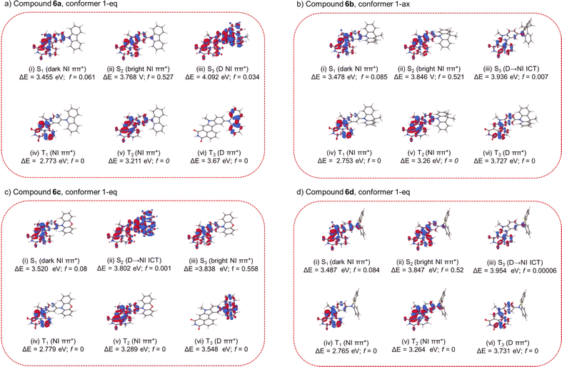 |
| | Fig. 3 EDDMs for the low-lying excited states of compound 6a–6d (with respect to the most favourable conformer), calculated at the ground-state equilibrium geometry (S0-min). The EDDMs are plotted in the form of isosurfaces with isovalues of ±0.005 e Å−3. The red and blue isosurfaces delimit regions in which the electron density is increased and decreased, respectively, relative to the S0 state. | |
Photophysics in solution and in the solid state
Bearing theoretical predictions, we next performed photophysical measurements on unfunctionalized core 4 and the target dyes 6a–6d to thoroughly understand their ground- and excited-state behaviour. Thereby, the basic photophysical analysis was conducted in three solvents of varying polarity, namely, dichloromethane (DCM), toluene, and tetrahydrofuran (THF) (Fig. 4). The results revealed distinct spectral features and photophysical properties for each compound, highlighting the influence of donor and acceptor structures on the excited-state dynamics and emission behaviour. The absorption spectra of the compounds revealed the presence of a common chromophore, the naphthalene imide core, which absorbs light at around 385 nm due to a π–π* transition. The slight red shift of the absorption band for compound 6a, attributed to its carbazole donor moiety, suggests a more extended π-system. This extension arises from the interaction between the π-system of the naphthalene imide core and the π-system of the carbazole donor (Fig. 4b). In general, the emission spectra of the investigated dyes revealed the presence of two distinct emission processes: local excitation (LE) and charge transfer (CT). In non-polar toluene, all compounds exhibited LE emission. This emission arises from the deactivation of the excited singlet state (S1) to the ground state (S0) through radiative transitions. Upon increasing the solvent polarity to DCM and THF, CT emission emerged, indicating the formation of a charge-separated state (CT). This state is formed when an electron is transferred from the donor moiety to the acceptor moiety, resulting in a strong dipole moment. CT emission occurs from the decay of the CT state back to the ground state through radiative transitions. Our parental compound 4, devoid of the auxiliary donor, proved to exhibit a single emission band in all three solvents, attributed to LE emission. This is because the CT state does not exist for this molecule due to the absence of donor–acceptor interactions. Considering compounds 6a and 6d, with carbazole and phenothiazine donors, respectively, a more pronounced CT emission in DCM and THF was shown. The reason for this behaviour is because of a stronger donor–acceptor interaction, which facilitates CT formation. On one hand, the emission wavelength determined for 6a exhibited a significant bathochromic shift with increasing polarity, indicating stronger charge transfer coupling. This is because the more polar solvent environment enhances the stabilization of the CT state. On the other hand, compound 6d displayed a more limited shift, indicating less efficient CT formation due to its quasi-axial conformation. This is likely due to the steric hindrance of the phenothiazine donor, which impedes the close proximity of the donor and acceptor moieties.
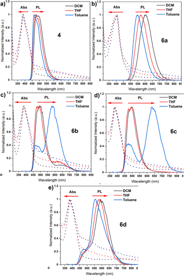 |
| | Fig. 4 Absorption and emission spectra of synthesized compounds in different solvents (a–e). | |
Going further to dyes 6b and 6c, equipped with DMAC and PXZ donors, a dual emission occurred in toluene. The latter emission arises from the balance between the donor and acceptor characteristics in these specific compounds. The blue emission peak is attributed to LE emission, while the other one is attributed to CT emission. The PLQY measurements confirmed the correlation between CT character and emission efficiency. Consecutively, compound 4 showed the highest PLQY of 55.7% in toluene as the lack of CT emission allows for efficient radiative deactivation of the excited state. The PLQY decreased for compounds 6a and 6b with increasing CT character, reaching 34.2% and 6.8%, respectively. This is translated to the presence of CT emission which contributes to non-radiative deactivation pathways, such as internal conversion and intersystem crossing. Compounds 6c and 6d, with the strongest CT emission, exhibited a PLQY of <0.1%, suggesting that the CT state acts as a non-radiative deactivation pathway, effectively quenching the fluorescence emission. The photophysical analysis of the five organic emitters revealed a complex interplay between the molecular structure, excited-state dynamics, and emission properties. The presence of donor and acceptor moieties significantly impacted the absorption and emission spectra, with the emergence of CT emission in more polar solvents. Having valuable knowledge on the behaviour of our dyes in solution, our attention was turned to the steady-state photoluminescence (PL) spectra of compounds 6a–6d, which were measured in two different host materials: the non-polar solid polymer Zeonex and the polar CBP matrix. A careful inspection of their emission spectra showed a red shift when the host was changed from Zeonex to CBP, indicating an increase in the polarity of the host environment (Fig. S1†). This red shift stems from the formation of a more stable charge-transfer (CT) state in the more polar CBP matrix. This observation clearly demonstrates the influence of the host environment on the excited-state dynamics of these molecules. The more polar CBP matrix stabilizes the CT state, leading to a longer radiative lifetime and a red shift in the emission wavelength. The PLQYs of compounds 6a, 6b, 6c, and 6d were recorded in both host materials under air and vacuum conditions. All compounds displayed notably higher PLQY values in the solid state (thin films) compared to the solution state. Considering these factors, the dyes 6c and 6d displayed the highest PLQY values, along with the longest emission wavelengths (595 nm). Such high PLQY values and long emission wavelengths can be assigned to the formation of a strong CT state in these compounds. The significantly higher PLQY values observed in the solid state (thin films) compared to the solution state further highlight the role of the host environment in enhancing the emission efficiency of these molecules. The rigidity of the Zeonex host is known to dampen vibronic coupling, thereby preventing fast RISC which corresponds to the RTP emission, and this phenomenon is also visible in our case. Nevertheless, RISC still occurs with a significant TADF contribution (6c and 6d) due to the relatively small singlet-triplet gap. These factors render both dyes, 6c and 6d, particularly appealing as emitting systems for achieving high-efficiency OLED emitters, which is closely associated with their stronger CT state.
In view of their prospective employment as TADF OLED emitters, significant attention was devoted to time-resolved PL measurements conducted in both Zeonex (Fig. 5) and CBP (Fig. 6) to explore the excited-state dynamics of these molecules. The entire set of dyes exhibited both fast emissive components (fluorescence) and long-lived emissive components. At low temperatures (10 K), the long-lived emissive components were attributed to phosphorescence. This is because the ISC rate is very slow at low temperatures, allowing for the population of the triplet excited state (T1) to persist for a longer period of time. Conversely, with increasing temperature, the phosphorescence components decreased, while the long-lived emissive components attributed to thermally activated delayed fluorescence (TADF) increased.
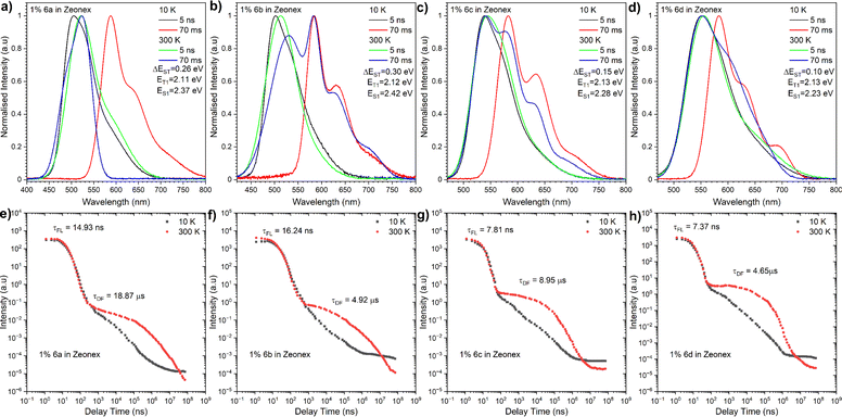 |
| | Fig. 5 Time-resolved PL spectra (a–d) and decay profiles (intensity vs. delay time) (e–h) of compounds 6a–6d in Zeonex®. The energies correspond to the maximum emission peaks and λex = 355 nm. | |
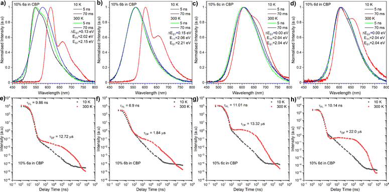 |
| | Fig. 6 Time-resolved PL spectra (a–d) and decay profiles (intensity vs. delay time) (e–h) of compounds 6a–6d in CBP. The energies correspond to the maximum emission peaks and λex = 355 nm. | |
For compound 6a, the TADF emission was observed in both microsecond and millisecond delay times, while the dual TADF and room-temperature phosphorescence (RTP) emission was observed in the millisecond delay time regime for compounds 6b–6d. This dual emission behaviour could be explained by the rigidity of the Zeonex host, which prevents rapid intersystem crossing (ISC) from the singlet excited state (S1) to the triplet excited state (T1). As a result, the population of the S1 state can persist for a longer period of time, allowing for more efficient ISC to T1 and delayed fluorescence emission. The energy level structure of compounds 6a–6d was inferred from maximum emission energy of the fluorescence and phosphorescence spectra. The analysis disclosed that the energy difference between the S1 and T1 states for these molecules in the Zeonex host was in the range of 0.15 to 0.3 eV (Table 1). This energy difference is in line with the observation of TADF emission. Likewise, the energy level structure of our dyes in the CBP matrix was determined, uncovering even lower energies and a narrower singlet-triplet gap. Moreover, the T1 state for the entire array of compounds proved to be located on the electron-deficient NMI core, while the S1 state was defined as a charge transfer state between the donor and acceptor moieties. We next proceeded to analyse the excited-state dynamics of our NMI-Ind dyes (6ad) in CBP-doped films using TR-PL measurements. In contrast to the dual emission behaviour observed in Zeonex, all compounds displayed a single emission peak in CBP, implying a predominance of TADF emission. This is essentially in accordance with the significantly smaller energy difference between the singlet excited state (S1) and triplet excited state (T1) in CBP compared to Zeonex. The energy gap between the S1 and T1 states varied for compounds 6a, 6b, 6c, and 6d, being 0.13 eV, 0.15 eV, 0.15 eV, and 0 eV, respectively. The extremely small energy splitting, denoted particularly for dyes 6c and 6d, indicates their significantly improved TADF character compared to Cz (6a) and DMAC (6b) derivatives. The delayed emission spectra of all compounds in CBP were found to be on the same energy level as the phosphorescence spectra. This suggests that the delayed emission reflects the same excited state as phosphorescence, which is the triplet excited state (T1). The very broad phosphorescence emission in CBP further supports the hypothesis that it arises from a mixed CT and LE emission. The emission wavelengths of all investigated compounds in CBP were lower than those in Zeonex, consistent with the more polar nature of the CBP matrix. This red shift is the hallmark of a stronger CT state formed in CBP, contrary to Zeonex. The observation that the location of the S1 state is within the electron-donating fragment while the T1 state is within the electron-deficient one is in perfect agreement with the presence of a strong CT state in this class of dyes. This is thereby responsible for the red-shifted emission, high PLQY, and efficient TADF processes identified predominantly for 6c and 6d which constitute a great premise ahead of OLED device fabrication.
Table 1 Summary of the general photophysical properties obtained from time-resolved spectra
| Dye |
λ
em
[nm] |
Host |
ϕ
PL
|
τ
PF
[ns] |
τ
DF
[μs] |
τ
RTP
[ms] |
DE/PFf |
k
r
, 107 s−1 |
k
nr
, 108 s−1 |
k
ISC
, 106 s−1 |
k
RISC
, 105 s−1 |
S1i [eV] |
T1i [eV] |
ΔESTj [eV] |
|
The maximum wavelength of photoluminescence spectra.
Photoluminescence quantum yield in the host under vacuum.
Prompt fluorescence (PF) lifetime.
Delayed fluorescence (DF) lifetime.
Room temperature phosphorescence (RTP) lifetime.
Ratio of delayed emission (DF & RTP) to prompt fluorescence (PF).
Estimates of kr and knr assuming that the emitting state is formed with unit efficiency such that kr = ϕ/τ and knr = (1 − ϕ)/τ.22
Values of reverse intersystem crossing rate constant, kRISC = (DF/PF)/τDF.22
Singlet and triplet energy (error ± 0.03 eV).
Energy splitting (error ± 0.05 eV); all parameters estimated at 300 K.
|
|
4
|
468 |
Zeonex |
73.3 |
5.75 |
— |
— |
— |
127.48 |
4.64 |
— |
— |
2.64 |
2.10 |
0.537 |
| 508 |
CBP |
41.1 |
8.11 |
— |
— |
— |
50.68 |
7.26 |
— |
— |
2.45 |
2.02 |
0.429 |
|
6a
|
527 |
Zeonex |
67.1 |
14.93 |
18.87 |
— |
1.49 |
30.61 |
2.20 |
2.14 |
0.08 |
2.37 |
2.11 |
0.264 |
| 552 |
CBP |
92.4 |
9.86 |
12.72 |
— |
1.27 |
72.52 |
0.77 |
2.29 |
0.10 |
2.15 |
2.02 |
0.121 |
|
6b
|
517 |
Zeonex |
77.3 |
16.24 |
4.92 |
4.41 |
1.71 |
17.55 |
1.40 |
3.89 |
0.55 |
2.42 |
2.12 |
0.296 |
| 552 |
CBP |
82.8 |
6.9 |
1.84 |
— |
2.70 |
96.38 |
2.49 |
2.85 |
0.68 |
2.21 |
2.06 |
0.151 |
|
6c
|
552 |
Zeonex |
66.5 |
7.81 |
8.95 |
2.77 |
4.64 |
15.11 |
4.29 |
10.53 |
0.63 |
2.28 |
2.13 |
0.15 |
| 596 |
CBP |
94.8 |
11.01 |
13.32 |
— |
6.77 |
33.24 |
0.47 |
5.58 |
0.19 |
2.04 |
2.04 |
0.00 |
|
6d
|
547 |
Zeonex |
13.6 |
7.37 |
4.65 |
5.25 |
6.29 |
2.58 |
11.72 |
11.67 |
1.54 |
2.23 |
2.13 |
0.11 |
| 594 |
CBP |
95.3 |
10.14 |
22 |
— |
7.38 |
19.63 |
0.46 |
7.80 |
0.11 |
2.04 |
2.04 |
0.00 |
OLED devices
Having identified the potential of our dyes to act as highly efficient TADF OLED emitters, the appropriate OLED structure was selected benefitting from cyclic voltammetry (CV), which serves as a powerful electrochemical technique utilized to investigate the redox properties of organic molecules. In the context of OLED emitters, it offers valuable insights into the electrochemical stability of the compounds, a critical factor for ensuring their long-term performance in OLED devices. Therefore, the HOMO and LUMO energy levels of the compounds were determined by cyclic voltammetry (CV) (Fig. 52, ESI†). For each organic emitter in series (6a–6d), CV measurements were performed in a DCM solution to assess their electrochemical stability at both p- and n-doping sites. The CV profiles revealed very good stability for all compounds, indicating their potential for long-term operation in OLED devices. Hence, to explore the applicability of our TADF dyes (6a–6d) as emitters in OLED devices, the device structures were fabricated using a thermal evaporation technique. As shown in Fig. 7a, the optimal device configuration for all compounds was found to be: indium tin oxide (ITO, as the anode), 1,4,5,8,9,11-hexaazatriphenylenehexacarbonitrile (HAT-CN) as the hole-transporting layer, (10 nm)/N,N′-di(1-naphthyl)-N,N′-diphenyl-(1,1′-biphenyl)-4,4′-diamine (NPB) (30 nm) to act as an exciton blocking layer and 10% of 6a, 6b, 6c or 6d in CBP (30 nm)/1,3,5-tri(m-pyridin-3-ylphenyl)benzene (TmPyPB) (40 nm) as the electron transporting layer and LiF (1 nm), which alters the work function of the Al cathode (100 nm). On top of this, the fabricated OLED devices underwent characterization using various techniques to evaluate their performance. In this regard, the electroluminescence (EL) spectra of the devices revealed a red shift in emission wavelength compared to the solution state (Fig. 7b and c), which is consistent with the formation of a stronger CT state in the solid state. The external quantum efficiency (EQE) of the devices was measured as a function of the applied voltage (Fig. 7d). The EQE values were determined to range from 6.4% for the dye compound 6a (NMI-Ind-TBCz) to 23.6% for compound 6d (NMI-Ind-TBCz). These values are significantly higher than the theoretical maximum for OLED devices based on only fluorescence emission (ca. 5%). The luminance of the devices was also measured as a function of the applied voltage (Fig. 7e). The highest luminance, reaching around 38![[thin space (1/6-em)]](https://www.rsc.org/images/entities/char_2009.gif) 000 cd m−2, was observed for compound 6d, which also exhibited the highest EQE, which is pointed out in Fig. 7f. To investigate the TADF mechanism in the fabricated OLED devices the results were compared with those of time-resolved photoluminescence (TRPL) measurements. The TRPL measurements described above revealed a long-lived emission component that decayed over a nanosecond time scale. This long-lived emission component was attributed to TADF emission, consistent with the high EQE values observed for these devices. Thereby, the demonstrated findings obtained for our emitters (6a–6d) appear promising for their utilization as OLED emitters. The formation of a strong CT state in the solid state leads to red-shifted emission and high PLQY values. The use of CBP as a host material further enhances the TADF efficiency of these compounds, resulting in OLED devices with EQE values that surpass the theoretical maximum. It must indeed be stressed that red-emissive dye 6d bearing a twisted PTZ unveiled the most pronounced performance, with an EQE of 23.6%, accompanied by a luminance of 38
000 cd m−2, was observed for compound 6d, which also exhibited the highest EQE, which is pointed out in Fig. 7f. To investigate the TADF mechanism in the fabricated OLED devices the results were compared with those of time-resolved photoluminescence (TRPL) measurements. The TRPL measurements described above revealed a long-lived emission component that decayed over a nanosecond time scale. This long-lived emission component was attributed to TADF emission, consistent with the high EQE values observed for these devices. Thereby, the demonstrated findings obtained for our emitters (6a–6d) appear promising for their utilization as OLED emitters. The formation of a strong CT state in the solid state leads to red-shifted emission and high PLQY values. The use of CBP as a host material further enhances the TADF efficiency of these compounds, resulting in OLED devices with EQE values that surpass the theoretical maximum. It must indeed be stressed that red-emissive dye 6d bearing a twisted PTZ unveiled the most pronounced performance, with an EQE of 23.6%, accompanied by a luminance of 38![[thin space (1/6-em)]](https://www.rsc.org/images/entities/char_2009.gif) 000 cd m−2 and bears Commission Internationale de l'Éclairage (CIE) coordinates to be (0.598, 0.394, Fig. 7b). It is worth mentioning that regardless of the dye implemented as a TADF organic emitter (6a–6d) for the optimized device structure bearing the CBP host material, a significantly reduced roll-off phenomenon is observed as underlined in Table 2. The roll-off in OLED devices, which refers to the decrease in efficiency with increasing luminance, is a major challenge in OLED technology and limits their commercial applications. Several factors can contribute to roll-off, including carrier trapping, exciton quenching, and voltage droop. Interestingly, for the emitters herein investigated, these factors appear to have a minor impact as seen in Table 2.
000 cd m−2 and bears Commission Internationale de l'Éclairage (CIE) coordinates to be (0.598, 0.394, Fig. 7b). It is worth mentioning that regardless of the dye implemented as a TADF organic emitter (6a–6d) for the optimized device structure bearing the CBP host material, a significantly reduced roll-off phenomenon is observed as underlined in Table 2. The roll-off in OLED devices, which refers to the decrease in efficiency with increasing luminance, is a major challenge in OLED technology and limits their commercial applications. Several factors can contribute to roll-off, including carrier trapping, exciton quenching, and voltage droop. Interestingly, for the emitters herein investigated, these factors appear to have a minor impact as seen in Table 2.
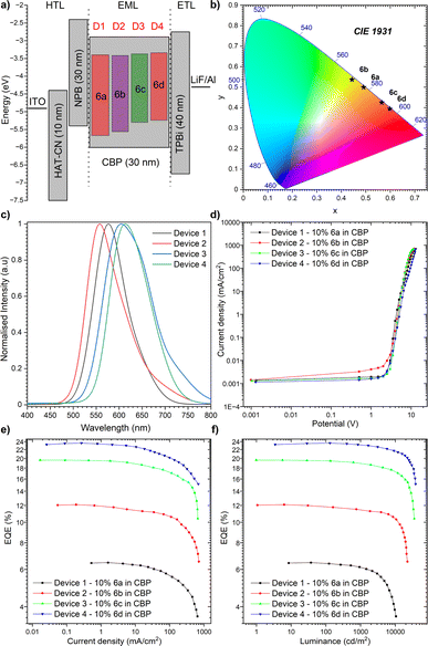 |
| | Fig. 7 The characteristics of the OLED devices: (a) device configuration; (b) CIE diagram of emission colours; (c) electroluminescence spectra; (d) current density–bias characteristics (see also Fig. 53, ESI†); (e) EQE–current density characteristics; (f) luminance–current density characteristics. | |
Table 2 EL data of the devicesa
| Device |
Turn-on voltage [V] |
Peak position [nm] |
L
max [cd m−2] |
CIE co-ordinates (x,y) |
EQE (%)/roll-off (%) |
| Max |
100 cd m−2 |
1000 cd m−2 |
10![[thin space (1/6-em)]](https://www.rsc.org/images/entities/char_2009.gif) 000 cd m−2 000 cd m−2 |
|
The roll-off was calculated as 100 × ((EQEmax − EQE)/EQEmax).
|
|
1
|
2.7 |
577 |
10![[thin space (1/6-em)]](https://www.rsc.org/images/entities/char_2009.gif) 481 481 |
0.491, 0.499 |
6.45 |
6.40/0.78 |
6.13/4.22 |
3.72/39.31 |
|
2
|
2.9 |
557 |
22![[thin space (1/6-em)]](https://www.rsc.org/images/entities/char_2009.gif) 379 379 |
0.443, 0.537 |
12.10 |
11.84/2.12 |
11.44/3.38 |
10.43/8.83 |
|
3
|
2.8 |
604 |
35![[thin space (1/6-em)]](https://www.rsc.org/images/entities/char_2009.gif) 221 221 |
0.565, 0.425 |
19.63 |
19.48/0.76 |
18.95/2.72 |
17.22/9.13 |
|
4
|
2.8 |
613 |
38![[thin space (1/6-em)]](https://www.rsc.org/images/entities/char_2009.gif) 319 319 |
0.598, 0.394 |
23.62 |
23.60/0.08 |
23.15/1.91 |
21.61/6.65 |
This behaviour is meaningful for device 4 composed of the red-emitting dye 6d. Importantly, we only noticed a slight drop in the electroluminescence efficiency (21.62%) along with a strong luminance of 10![[thin space (1/6-em)]](https://www.rsc.org/images/entities/char_2009.gif) 000 cd m−2 as demonstrated in Table 2 (6.65% for 6d, in contrast to remaining dyes 6a–6c whose roll-off ranges from 39.31–9.13%, respectively). In light of this development, it can be claimed that our NMI-Ind-PTZ/PXZ dyes hold great potential for their introduction into high-efficiency OLED devices with a wide range of applications, including displays, lighting, and imaging. Moreover, when compared with recently reported orange and particularly red TADF-OLED devices (Fig. 8), the emitting system presented here stands out as one of the most promising ones to date, especially when related to those constructed on widely spread imide and phenazine PAH scaffolds (for a detailed comparison see Table 2, ESI†).
000 cd m−2 as demonstrated in Table 2 (6.65% for 6d, in contrast to remaining dyes 6a–6c whose roll-off ranges from 39.31–9.13%, respectively). In light of this development, it can be claimed that our NMI-Ind-PTZ/PXZ dyes hold great potential for their introduction into high-efficiency OLED devices with a wide range of applications, including displays, lighting, and imaging. Moreover, when compared with recently reported orange and particularly red TADF-OLED devices (Fig. 8), the emitting system presented here stands out as one of the most promising ones to date, especially when related to those constructed on widely spread imide and phenazine PAH scaffolds (for a detailed comparison see Table 2, ESI†).
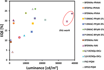 |
| | Fig. 8 Summarized results for orange and red TADF-OLEDs reported so far with an emphasis on the roll-off ratio. EQE and luminance were estimated based on the reported EL spectra. | |
Conclusion
In summary, we have introduced a new approach for the construction of strongly red-emitting and persistent TADF dyes. Our design involved the annulation of NMI with indole, incorporating auxiliary electron-rich moieties, to ensure robust conjugation and charge transfer characteristics. Among the resulting compounds, phenothiazine-decorated dyes (NMI-Ind-PTZ) exhibited superb photoluminescence quantum yields (PLQYs) of 95.6% and very small ΔEST values (<0.05 eV), as evidenced by short, delayed lifetimes of 22 μs in 10 wt% doped CBP films. Implementing our best-performing emitter in OLEDs demonstrated highly efficient performance with an EQEmax of 23.6%, emitting at a red electroluminescence peak of λEL of 613 nm with a low Von of 2.8 V. Furthermore, the luminance was maintained at 10![[thin space (1/6-em)]](https://www.rsc.org/images/entities/char_2009.gif) 000 cd m−2 with an EQE of 21.6%, revealing a nearly suppressed roll-off ratio and positioning these red OLEDs among the most persistent devices (Lmax = 38
000 cd m−2 with an EQE of 21.6%, revealing a nearly suppressed roll-off ratio and positioning these red OLEDs among the most persistent devices (Lmax = 38![[thin space (1/6-em)]](https://www.rsc.org/images/entities/char_2009.gif) 319 cd m−2). This addresses one of the most critical challenges in TADF OLEDs from the standpoint of real-life applications.
319 cd m−2). This addresses one of the most critical challenges in TADF OLEDs from the standpoint of real-life applications.
Data availability
The data that support the findings of this study are available in the ESI† of this article. The calculated equilibrium geometries of the compounds under study were deposited at the Zenodo (https://zenodo.org/records/10721177) database (https://doi.org/10.5281/zenodo.10721176).
Author contributions
M. L. conceived and supervised the project; M. G. and M. L. designed, synthesized, and characterized all emitters; D. K. and G. W. Ł. carried out basic photophysical and time-resolved spectroscopic studies and fabricated and analysed OLED devices, while P. D. analysed and interpreted the spectroscopic results; M. A. K. and A. K. performed the computational studies; M. L. conceptualized the manuscript. M. A. K., A. K., P. D. and M. L. contributed to writing the manuscript.
Conflicts of interest
The patent call dealing with synthesis of herein discussed compounds constitutes a subject of the patent call (P.444060) submitted to the Polish Patent Office.
Acknowledgements
M. G. and M. L. acknowledge support from the National Science of Research and Development, Poland, Grant No. LIDER/21/0077/L-11/19/NCBR/2020. M. L. is a recipient of a scholarship awarded by the Polish Ministry of Education and Science to outstanding young scientists (2/DSP/2021). M. A. K. acknowledges funding from the European Union's Horizon 2020 research and innovation program under the Marie Skłodowska-Curie grant agreement No. 847413. A. K. acknowledges support from the National Science Centre, Poland, Grant No. 2020/39/B/ST4/01952. This work has been published as part of an international co-financed project funded by the program of the Minister of Science and Higher Education entitled “PMW” in the years 2020–2024; agreement no. 5005/H2020-MSCA-COFUND/2019/2. The electronic structure calculations reported in this study were carried out with the use of the computational resources provided by the Wrocław Centre for Networking and Supercomputing (WCSS, http://wcss.pl) and the Centre of Informatics of the Tricity Academic Supercomputer and Network (CI TASK, https://task.gda.pl/). The publication was produced as part of the Doctoral Candidate's participation in a project of the National Agency for Academic Exchange within the framework of the “STER” Programme. – Internationalization of Doctoral Schools” as part of the project “Curriculum for advanced doctoral education & training – CADET Academy of Lodz University of Technology. G. W. S. acknowledges support from the National Centre for Research and Development, Poland, Grant No. POLBER/5/63/PrintedQDD/2022. P. D. acknowledges National Science Centre, Poland, Grant No. 2022/45/B/ST5/03712.
References
- O. Ostroverkhova, Chem. Rev., 2016, 116, 13279–13412 CrossRef CAS PubMed.
- X. Guo, A. Facchetti and T. J. Marks, Chem. Rev., 2014, 114, 8943–9021 CrossRef CAS PubMed.
- H. Lee, Z. Jiang, T. Yokota, K. Fukuda, S. Park and T. Someya, Mater. Sci. Eng., R, 2021, 146, 100631 CrossRef.
- J. V. Dcosta, D. Ochoa and S. Sanaur, Adv. Sci., 2023, 10(31), 2302752 CrossRef.
- A. Gumyusenge, Acc. Mater. Res., 2022, 3, 669–671 CrossRef CAS.
- L. Xu, H. Jia, C. Zhang, B. Yin and J. Yao, Chem. Sci., 2023, 14, 8723–8742 RSC.
- M. A. Bryden and E. Zysman-Colman, Chem. Soc. Rev., 2021, 50, 7587–7680 RSC.
- G. Hong, X. Gan, C. Leonhardt, Z. Zhang, J. Seibert, J. M. Busch and S. Bräse, Adv. Mater., 2021, 33, 2005630 CrossRef CAS PubMed.
- H. Uoyama, K. Goushi, K. Shizu, H. Nomura and C. Adachi, Nature, 2012, 492, 234–238 CrossRef CAS PubMed.
- K. Goushi, K. Yoshida, K. Sato and C. Adachi, Nat. Photonics, 2012, 6, 253–258 CrossRef CAS.
- Y. Liu, C. Li, Z. Ren, S. Yan and M. R. Bryce, Nat. Rev. Mater., 2018, 3, 18020 CrossRef CAS.
- Y. Qin, G. Li, T. Qi and H. Huang, Mater. Chem. Front., 2020, 4, 1554–1568 RSC.
- M. Li, Y. Liu, R. Duan, X. Wei, Y. Yi, Y. Wang and C.-F. Chen, Angew. Chem., Int. Ed., 2017, 56, 8818–8822 CrossRef CAS PubMed.
- Z. Huang, Z. Bin, R. Su, F. Yang, J. Lan and J. You, Angew. Chem., Int. Ed., 2020, 59, 9992–9996 CrossRef CAS PubMed.
- Y. Hu, Y. Zhang, W. Han, J. Li, X. Pu, D. Wu, Z. Bin and J. You, Chem. Eng. J., 2022, 428, 131186 CrossRef CAS.
- W. Zeng, H.-Y. Lai, W.-K. Lee, M. Jiao, Y.-J. Shiu, C. Zhong, S. Gong, T. Zhou, G. Xie, M. Sarma, K.-T. Wong, C.-C. Wu and C. Yang, Adv. Mater., 2018, 30, 1704961 CrossRef PubMed.
- T. Chen, C. Lu, Z. Chen, X. Gong, C. Wu and C. Yang, Chem.–Eur. J., 2021, 27, 3151–3158 CrossRef CAS PubMed.
- T. Chen, C.-H. Lu, C.-W. Huang, X. Zeng, J. Gao, Z. Chen, Y. Xiang, W. Zeng, Z. Huang, S. Gong, C.-C. Wu and C. Yang, J. Mater. Chem. C, 2019, 7, 9087–9094 RSC.
- K. Bartkowski, P. Zimmermann Crocomo, M. A. Kochman, D. Kumar, A. Kubas, P. Data and M. Lindner, Chem. Sci., 2022, 13, 10119–10128 RSC.
- C. Yin, Y. Zhang, T. Huang, Z. Liu, L. Duan and D. Zhang, Sci. Adv., 2022, 8, eabp9203 CrossRef CAS PubMed.
- K. Bartkowski, A. K. Gupta, T. Matulaitis, M. Morawiak, E. Zysman-Colman and M. Lindner, Org. Chem. Front., 2024, 11, 755–760 RSC.
- F. B. Dias, T. J. Penfold and A. P. Monkman, Methods Appl. Fluoresc., 2017, 5, 012001 CrossRef PubMed.
|
| This journal is © The Royal Society of Chemistry 2024 |
Click here to see how this site uses Cookies. View our privacy policy here.  Open Access Article
 b,
Maja
Morawiak
a,
Gabriela
Wiosna-Sałyga
b,
Adam
Kubas
b,
Maja
Morawiak
a,
Gabriela
Wiosna-Sałyga
b,
Adam
Kubas
 *c,
Przemysław
Data
 *b and
Marcin
Lindner
 *a
*a
![[thin space (1/6-em)]](https://www.rsc.org/images/entities/char_2009.gif) 000 cd m−2. This results in a unique roll-off ratio (EQE10 000 = 21.6%), delineating a straightforward path for their commercial use in lighting and display technologies.
000 cd m−2. This results in a unique roll-off ratio (EQE10 000 = 21.6%), delineating a straightforward path for their commercial use in lighting and display technologies.![[thin space (1/6-em)]](https://www.rsc.org/images/entities/char_2009.gif) 000 cd m−2 with an EQE of 21.6%. This output indicates an unprecedented roll-off ratio and greatly improved operational stability, unlocking the full potential of OLED applications for red TADF emitters.
000 cd m−2 with an EQE of 21.6%. This output indicates an unprecedented roll-off ratio and greatly improved operational stability, unlocking the full potential of OLED applications for red TADF emitters.


![[thin space (1/6-em)]](https://www.rsc.org/images/entities/char_2009.gif) 000 cd m−2, was observed for compound 6d, which also exhibited the highest EQE, which is pointed out in Fig. 7f. To investigate the TADF mechanism in the fabricated OLED devices the results were compared with those of time-resolved photoluminescence (TRPL) measurements. The TRPL measurements described above revealed a long-lived emission component that decayed over a nanosecond time scale. This long-lived emission component was attributed to TADF emission, consistent with the high EQE values observed for these devices. Thereby, the demonstrated findings obtained for our emitters (6a–6d) appear promising for their utilization as OLED emitters. The formation of a strong CT state in the solid state leads to red-shifted emission and high PLQY values. The use of CBP as a host material further enhances the TADF efficiency of these compounds, resulting in OLED devices with EQE values that surpass the theoretical maximum. It must indeed be stressed that red-emissive dye 6d bearing a twisted PTZ unveiled the most pronounced performance, with an EQE of 23.6%, accompanied by a luminance of 38
000 cd m−2, was observed for compound 6d, which also exhibited the highest EQE, which is pointed out in Fig. 7f. To investigate the TADF mechanism in the fabricated OLED devices the results were compared with those of time-resolved photoluminescence (TRPL) measurements. The TRPL measurements described above revealed a long-lived emission component that decayed over a nanosecond time scale. This long-lived emission component was attributed to TADF emission, consistent with the high EQE values observed for these devices. Thereby, the demonstrated findings obtained for our emitters (6a–6d) appear promising for their utilization as OLED emitters. The formation of a strong CT state in the solid state leads to red-shifted emission and high PLQY values. The use of CBP as a host material further enhances the TADF efficiency of these compounds, resulting in OLED devices with EQE values that surpass the theoretical maximum. It must indeed be stressed that red-emissive dye 6d bearing a twisted PTZ unveiled the most pronounced performance, with an EQE of 23.6%, accompanied by a luminance of 38![[thin space (1/6-em)]](https://www.rsc.org/images/entities/char_2009.gif) 000 cd m−2 and bears Commission Internationale de l'Éclairage (CIE) coordinates to be (0.598, 0.394, Fig. 7b). It is worth mentioning that regardless of the dye implemented as a TADF organic emitter (6a–6d) for the optimized device structure bearing the CBP host material, a significantly reduced roll-off phenomenon is observed as underlined in Table 2. The roll-off in OLED devices, which refers to the decrease in efficiency with increasing luminance, is a major challenge in OLED technology and limits their commercial applications. Several factors can contribute to roll-off, including carrier trapping, exciton quenching, and voltage droop. Interestingly, for the emitters herein investigated, these factors appear to have a minor impact as seen in Table 2.
000 cd m−2 and bears Commission Internationale de l'Éclairage (CIE) coordinates to be (0.598, 0.394, Fig. 7b). It is worth mentioning that regardless of the dye implemented as a TADF organic emitter (6a–6d) for the optimized device structure bearing the CBP host material, a significantly reduced roll-off phenomenon is observed as underlined in Table 2. The roll-off in OLED devices, which refers to the decrease in efficiency with increasing luminance, is a major challenge in OLED technology and limits their commercial applications. Several factors can contribute to roll-off, including carrier trapping, exciton quenching, and voltage droop. Interestingly, for the emitters herein investigated, these factors appear to have a minor impact as seen in Table 2.

![[thin space (1/6-em)]](https://www.rsc.org/images/entities/char_2009.gif) 000 cd m−2
000 cd m−2![[thin space (1/6-em)]](https://www.rsc.org/images/entities/char_2009.gif) 481
481![[thin space (1/6-em)]](https://www.rsc.org/images/entities/char_2009.gif) 379
379![[thin space (1/6-em)]](https://www.rsc.org/images/entities/char_2009.gif) 221
221![[thin space (1/6-em)]](https://www.rsc.org/images/entities/char_2009.gif) 319
319![[thin space (1/6-em)]](https://www.rsc.org/images/entities/char_2009.gif) 000 cd m−2 as demonstrated in Table 2 (6.65% for 6d, in contrast to remaining dyes 6a–6c whose roll-off ranges from 39.31–9.13%, respectively). In light of this development, it can be claimed that our NMI-Ind-PTZ/PXZ dyes hold great potential for their introduction into high-efficiency OLED devices with a wide range of applications, including displays, lighting, and imaging. Moreover, when compared with recently reported orange and particularly red TADF-OLED devices (Fig. 8), the emitting system presented here stands out as one of the most promising ones to date, especially when related to those constructed on widely spread imide and phenazine PAH scaffolds (for a detailed comparison see Table 2, ESI†).
000 cd m−2 as demonstrated in Table 2 (6.65% for 6d, in contrast to remaining dyes 6a–6c whose roll-off ranges from 39.31–9.13%, respectively). In light of this development, it can be claimed that our NMI-Ind-PTZ/PXZ dyes hold great potential for their introduction into high-efficiency OLED devices with a wide range of applications, including displays, lighting, and imaging. Moreover, when compared with recently reported orange and particularly red TADF-OLED devices (Fig. 8), the emitting system presented here stands out as one of the most promising ones to date, especially when related to those constructed on widely spread imide and phenazine PAH scaffolds (for a detailed comparison see Table 2, ESI†).
![[thin space (1/6-em)]](https://www.rsc.org/images/entities/char_2009.gif) 000 cd m−2 with an EQE of 21.6%, revealing a nearly suppressed roll-off ratio and positioning these red OLEDs among the most persistent devices (Lmax = 38
000 cd m−2 with an EQE of 21.6%, revealing a nearly suppressed roll-off ratio and positioning these red OLEDs among the most persistent devices (Lmax = 38![[thin space (1/6-em)]](https://www.rsc.org/images/entities/char_2009.gif) 319 cd m−2). This addresses one of the most critical challenges in TADF OLEDs from the standpoint of real-life applications.
319 cd m−2). This addresses one of the most critical challenges in TADF OLEDs from the standpoint of real-life applications.


