 Open Access Article
Comparison of voltammetric methods used in the interrogation of electrochemical aptamer-based sensors†
Elsi
Verrinder
 ad,
Kaylyn K.
Leung
 ad,
Murat Kaan
Erdal
 e,
Lior
Sepunaru
 ab and
Kevin W.
Plaxco
 *abcd
*abcd
aDepartment of Chemistry and Biochemistry, University of California, Santa Barbara, Santa Barbara, California 93106, USA. E-mail: kwp@ucsb.edu
bBiomolecular Science and Engineering Graduate Program, University of California, Santa Barbara, Santa Barbara, California 93106, USA
cBiological Engineering Graduate Program, University of California, Santa Barbara, Santa Barbara, California 93106, USA
dCenter for Bioengineering, University of California Santa Barbara, Santa Barbara, CA 93106, USA
eDepartment of Electrical and Computer Engineering, University of California Santa Barbara, Santa Barbara, CA 93106, USA
First published on 2nd November 2023
Abstract
Electrochemical aptamer-based (EAB) sensors are the first continuous molecular measurement technology that is both (1) able to function in situ in the living body and (2) independent of the chemical reactivity of its targets, rendering it generalizable to a wide range of analytes. Comprised of an electrode-bound, redox-reporter-modified aptamer, signal generation in EAB sensors arises when binding to this target-recognizing aptamer causes a conformation change that, in turn, alters the rate of electron transfer to and from the redox reporter to the electrode surface. A range of electrochemical approaches, including both voltammetric (e.g., cyclic, square wave, and alternating current voltammetry) and non-voltammetric (e.g., chronoamperometry, electrochemical phase interrogation) methods have been used to monitor this change in transfer rate, with square wave voltammetry having dominated recent reports. To date, however, the literature has seen few direct comparisons of the performance of these various approaches. In response we describe here comparisons of EAB sensors interrogated using square wave, differential pulse, and alternating current voltammetry. We find that, while the noise associated with AC voltammetry (in vitro in 37 °C whole blood) is exceptionally low, neither this approach nor differential pulse voltammetry support accurate drift correction under these same conditions, suggesting that neither approach is suitable for deployment in vivo. Square wave voltammetry, in contrast, matches or surpasses the gain achieved by the other two approaches, achieves good signal-to-noise, and supports high-accuracy drift correction in 37 °C whole blood. Taken together, these results finally confirm that square wave voltammetry is the preferred pulsed voltammetric method for interrogating EAB sensors in complex biological fluids.
Introduction
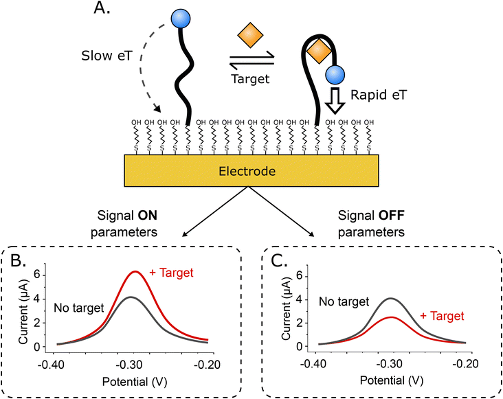
Electrochemical aptamer-based (EAB) sensors1 are an in vivo molecular measurement technology that, because it is independent of the chemical reactivity of its targets, can be easily adapted to new targets. This is because, unlike, for example, in vivo glucose monitors, which rely on the ability of glucose oxidase to convert glucose and oxygen into an electrochemically detectable output (e.g., hydrogen peroxide), signal generation in EAB sensors is linked to a binding-induced conformational change in its target-recognizing aptamer (Fig. 1A), rendering the approach far more general. Because this signal transduction mechanism is also reagentless, wash-free, and rapidly reversible, EAB sensors support high-frequency, real-time molecular monitoring. Finally, because this signaling mechanism mimics the conformation-linked signaling seen in naturally occurring chemoperception systems, EAB sensors also perform well when placed in the living body, where they can be used to provide seconds-resolved, real-time drug and metabolite concentration measurements.2–7Signaling in EAB sensors arises when the binding-induced conformational change alters the rate of electron transfer from the methylene blue reporter to the electrode surface. Historically, we have used square wave voltammetry (SWV)8–11 to monitor this change, as the approach is particularly sensitive to electron transfer rate. For example, by “tuning” the square wave frequency we can render the sensor more sensitive to either rapid electron transfer, or slower electron transfer, producing either “signal on” (the signal increases upon target binding; Fig. 1B), or “signal off” (the signal decreases; Fig. 1C) behavior. Taking the difference between the two both increases the gain (the relative signal change seen at saturating target) and, in a method termed “kinetic differential measurements” (KDM), can be used to remove the drift (i.e., a gradual decrease in signal over time) seen when EAB sensors are deployed in vivo.2,6,7
While SWV has been the most widely used interrogation method for EAB sensors, it is not the only voltammetric approach that is sensitive to electron transfer rates. The first papers describing sensors in this broad class (of DNA-based electrochemical sensors), for example, employed cyclic voltammetry as the means of sensor interrogation.12 As this is less sensitive to transfer rate than many other electrochemical approaches, it soon fell out of favor. In the following years, the first papers specifically detailing EAB sensors employed alternating current voltammetry (ACV)1,13,14 and differential pulse voltammetry (DPV)15,16 as their interrogation methods, followed by square wave voltammetry in 2010.17 More recently still, a number of other electrochemical approaches have been adapted to this problem, including chronoamperometry,18 intermittent pulse amperometry,19 and electrochemical impedance methods.20,21 But because few direct comparisons of the performance of these approaches have been reported, it remains unclear which is optimal for any given sensor or application, much less whether or not any one of these approaches is universally superior for all sensors in this class. Moreover, since a wider application of EAB sensors still faces some challenges (as summarized by Arroyo-Currás et al.22), it is worth going deeper into different interrogation methods in an effort to optimize every aspect of EAB sensor performance. As a step in this direction, here we compare three voltammetric approaches, SWV, DPV and ACV, reserving for future studies cross comparisons with non-voltammetric approaches.
Results and discussion
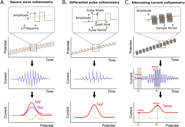
Here, we have characterized the performance of EAB sensors using SWV, DPV, and ACV, all of which are particularly sensitive to changes in electron transfer rate. In SWV, a square wave step potential is superimposed on a linear sweep base potential, with the current being sampled at the end of each forward and reverse step. Because of this, the observed current depends on the difference between the time scales of electron transfer and thereby, the square wave frequency (Fig. 2A). Specifically, if the length of the step is long relative to the rate of electron transfer, transfer will have largely decayed by the time the current is sampled, reducing the observed current. The closely related DPV employs a similar waveform, but adds a “quiet time” after each potential step in place of the reverse step (Fig. 2B). During this, the potential is returned to the baseline, allowing renewal of the diffusion layer. Finally, ACV employs a sinusoidal wave superimposed on an incrementally rising base potential (Fig. 2C). In this approach, the faradaic response depends on the frequency of the applied AC potential, with the maximum current response being seen at the frequency corresponding to the rate of electron transfer. The resulting signal is the measured amplitude of the AC current at each incremental potential step. In all methods, the peak is centered on the formal potential of the redox reporter.As our first comparison testbed we employed an established EAB sensor against the antibiotic vancomycin.4 This is comprised of a 45-base, vancomycin-binding aptamer chemisorbed onto a gold wire electrode that is paired with a platinum wire counter electrode and a silver/silver-chloride reference. To evaluate the performance of this sensor across the various electrochemical interrogation methods, we have employed three metrics. The first, signal gain, is the relative difference in peak current seen in the absence of target and presence of saturating target (here 500 μM vancomycin). The second, drift correction, we defined as the accuracy with which the decrease in relative signal seen for sensors placed in undiluted whole blood held at 37 °C can be corrected using differential (i.e., paired frequency) approaches.23,24 And as the final comparator, we determined the noise associated with each method when the sensor is operated in vitro in undiluted whole blood at 37 °C.
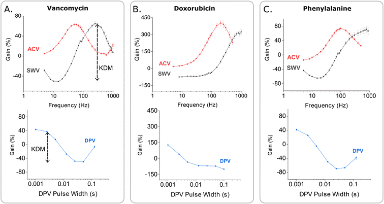
Consistent with the behavior of other EAB sensors,17,25 the gain of our vancomycin sensor is strongly dependent on square wave frequency, but only weakly dependent on square wave amplitude (Fig. 3A). Indeed, as noted above, the gain is such a strong function of frequency that it moves from positive at higher frequencies to negative at lower frequencies, reaching a maximum of +63.6(±1.5)% and a minimum of −45.5(±0.9)% at a target concentration of 500 μM and square wave frequencies of 300 and 20 Hz, respectively (these and the following “error bars” reflect standard deviations of measurements performed with independently fabricated sensors). On the contrary, changing the amplitude affects the raw current proportionally in both the absence and presence of target, leaving the signal gain relatively unchanged.
 | ||
| Fig. 3 EAB sensor gain is a strong function of the parameters that define the voltammetric methods used to interrogate them. To show this, here we present dependence of the signal gain of the vancomycin-detecting EAB sensor on the frequency and amplitude in SWV and ACV, and on pulse period and pulse width in DPV. (A) The gain measured using SWV is strongly dependent on the interrogation frequency, but only weakly dependent on the amplitude of the potential wave form. (B) DPV signal gain similarly varies with pulse width. It is, however, far less sensitive to the length of the quiet time (i.e., the difference between pulse period and pulse width) or the amplitude used (Fig. S3†). Here we employed an amplitude of 25 mV. Due to the larger number of tunable parameters associated with this approach, the DPV data set appears sparser than the corresponding SWV and ACV data sets. Given the smoothness of the resulting gain curves, however, we do not believe this significantly affects cross comparisons. (C) For ACV the signal gain is, like that of SWV, a strong function of frequency and only a weak function of amplitude. In contrast to what is seen with SWV, however, the gain remains positive at all AC frequencies. The measurements presented here were performed in PBS buffer at 37 °C using 500 μM vancomycin as the high target concentration. Error bars show the standard deviation of four independent electrodes. | ||
To perform KDM we take the difference between measurements collected at a pair of frequencies, one exhibiting “signal-on” (signal increases with increasing target) and the other “signal-off” (decreases with increasing target) behavior. Specifically, here we define KDM as:
In contrast to the related SWV, DPV is defined by two adjustable delay periods, which are encoded in the pulse width and the pulse period, with the length of the “quiet time” being the difference between the two (Fig. 2B). Exploring the effects of these on our test EAB sensor we find that while its signal gain is strongly dependent on the pulse width (i.e., the width of the positive pulse), it depends only very weakly on the pulse period. This is because the pulse width defines the electron transfer time scale that DPV is most sensitive to, rendering EAB performance a strong function of this parameter. The pulse period, in contrast, effectively defines the quiet time (the time the system has to “reset”). Once this period is sufficiently long, any further lengthening of it will not change sensor performance. We find the highest signal-on gain, when the pulse period is 0.025 s and pulse width 0.0025 s, and the greatest signal-off gain when the pulse period is 0.1 s and the pulse width 0.025 s. With these parameters, the gain reaches +42.1(±1.9)% and −49.0(±1.0)%, respectively, at 500 μM target. Employing KDM (i.e., taking the difference), the total gain reaches 91.1(±2.2)%. Finally, we find that the gain of sensors interrogated using DPV is relatively insensitive to the amplitude of the associated potential wave form (Fig. S3†).
As was true for SWV, when we interrogate our sensor using ACV we find that the signal gain is a strong function of frequency and only a weak function of amplitude (Fig. 3C). The minimum and maximum gains achieved using ACV, however, are seen at lower frequencies (5 Hz and 50 Hz, respectively) than those seen for SWV (Fig. 3A). They likewise produce lower gain, with the highest observed signal-on gain being just +63.3(±2.3)%, which we see at 50 Hz, and the minimum +4.6(±0.1)%, which we see at 5 Hz (both at 500 μM target). That is, in contrast to SWV and DPV, we observe no signal-off behavior at any frequency when employing ACV. Because of this, the KDM gain is only 58.6(±2.3)%.
Having identified the parameters for each interrogation method that produce the highest KDM-corrected signal gain, we next applied these in a head-to-head comparison of each interrogation approach by performing titrations of the sensor against its vancomycin target (Fig. 4). All three binding curves exhibit the expected Langmuir isotherm (i.e., hyperbolic) relationship between concentration and signal. By fitting the data to the Langmuir isotherm, we find that the maximum (KDM-enhanced) gains achieved with SWV and DPV reach 112.7(±2.9)% and 109.7(±1.7)%, respectively (here the maximum gain is the numerator in the Langmuir fit). In contrast, the maximum gain achieved with ACV reaches only 49.4(±1.3)%. When fitted to a Langmuir isotherm (see Materials and methods for details), two of the three approaches produce dissociation constants within error of one another – the estimated values being 66 ± 5 and 76 ± 6 μM for SWV and DPV, respectively. The value derived from our ACV data is somewhat smaller, at 46 ± 4 μM; the origins of this discrepancy are unclear to us.
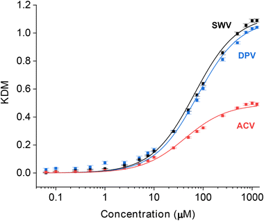 | ||
| Fig. 4 The maximum, KDM-derived signal gains (the relative change in signal between no target and saturating target) seen when our vancomycin-detecting EAB sensor is interrogated with SWV and DPV, are considerably larger than the gain seen with ACV interrogation. To illustrate this, here we present titration curves captured using the optimal frequency and amplitude pairs found for each approach (Fig. 3). For SWV, the highest gain signal-on and signal-off frequencies are 300 and 20 Hz. This produces a KDM-type gain of 112.7(±2.9)% (here defined as the numerator in the Langmuir fit). For DPV, the highest gain signal-on pulse period and pulse width pair is 0.025 s and 0.0025 s and the highest gain signal-off pair is 0.1 s and 0.025 s. Using these parameters, the KDM gain is 109.7(±1.7)%. For ACV, the highest gain signal-on and signal-off frequencies are 50 and 5 Hz, respectively, producing a KDM gain of 49.4(±1.3)%. The solid lines represent fits to the expected Langmuir isotherm with estimated binding midpoints of 66 ± 5, 76 ± 6 and 46 ± 4 μM for the SWV, DPV, and ACV data, respectively. These measurements were performed in PBS at 37 °C. The error bars, which are standard deviations obtained from four, independently fabricated electrodes, denote sensor-to-sensor reproducibility. | ||
Key to the use of EAB sensors in vivo is the ability of the SWV technique KDM to remove the drift invariably seen in such placements.2,6,7,23 To determine the ability of DPV and ACV to support similar drift correction we challenged our sensor in 37 °C whole blood, which we have found a good in vitro proxy for the in vivo environment.24 As required for KDM, we employed parameter pairs that drift in concert but for which the sensor responds differentially to the presence of target. As expected, all three approaches exhibit significant drift under these conditions (Fig. 5A). When we apply KDM to our SWV observations, however, this drift is almost entirely removed (Fig. 5B), leading to good accuracy in the sensor's response to challenges with 35 μM vancomycin (Fig. 5C), a value within the 6 to 35 μM clinical range of this drug.26 In contrast, KDM method does not accurately correct the drift seen for either DPV and ACV sensor interrogation, as even the frequency pairs that drift in closest concert still fail to entirely correct for the observed drift (Fig. 5B and C).
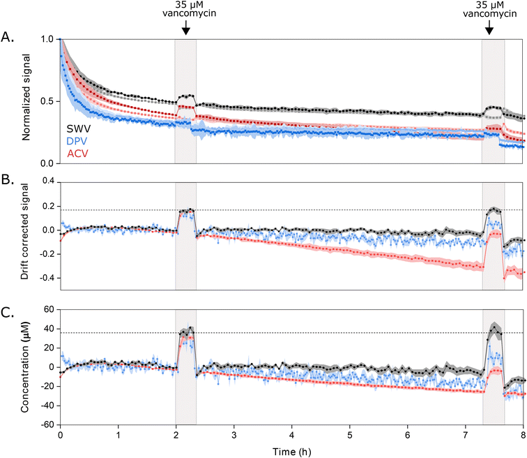 | ||
| Fig. 5 Sensors interrogated using DPV or ACV drift more significantly when challenged in undiluted whole blood (at 37 °C) than sensors interrogated using SWV, and the resulting drift is less correctable. (A) Normalized signals measured at the optimal signal-on (darker color) and signal-off (lighter color) voltammetric parameters illustrate the drift that occurs during multi-hour measurements under these harsh conditions. Here we normalized the signal for each method to the data point collected at 1 h, after the rapid, initial period of drift is over. (B) Using KDM, we can correct this drift for sensors interrogated via SWV. In contrast, this correction fails for sensors interrogated with either DPV or ACV. (C) Shown in the bottom panel are the KDM signals converted into estimated concentrations using calibration curves (Fig. S4†). With this, only the SWV measurements recover the value expected when we challenge the sensors with 35 μM vancomycin at 2 h and 7.5 h. Shading indicates standard deviations obtained from four independently fabricated electrodes. | ||
For our final comparator we determined the noise level for each approach by calculating the root mean square deviation (RMSD) from fitted data trends using the long-duration measurements we collected in 37 °C whole blood (Fig. 5). To obtain the fitted estimate of the data (red curves in Fig. 6), we use the cubic splines function in Matlab to extract the main trend hidden behind the noisy measurements (see ESI† for details) that were the average signal obtained using four electrodes (black dots in Fig. 6). Doing so, we found noise of 3.1 μM associated with SWV (Fig. 6A), 4.6 μM with DPV (Fig. 6B), and 1.9 μM with ACV (Fig. 6C). For the DPV studies here, we have used a quiet time of 22.5 ms for the signal-on parameters. This is short enough that capacitive contributions can be significant, suggesting that small fluctuations in the capacitive contribution may be the source of the higher noise seen for this technique. In contrast, as long as the frequencies used are neither too low nor too high, ACV is less sensitive to the capacitive current.27
 | ||
| Fig. 6 We calculated noise levels associated with each method (A: swv; B: DPV; C: ACV) as the root mean square deviation (RMSD) from the fitted data trends seen for our 37 °C whole blood studies (Fig. 5). The red curves represent the fitted estimate of the data, calculated from the average signals of four electrodes (black dots). | ||
The improved gain associated with the use of SWV to interrogate the vancomycin-detecting sensor also holds for other EAB sensors. To see this, we monitored the relative performance of established EAB sensors against the chemotherapeutic drug doxorubicin23 and the amino acid phenylalanine7 when interrogated via all three voltammetric methods. Doing so we find that, while ACV produces the highest signal-on gain for both, SWV interrogation produces the largest signal gain when KDM is applied to the phenylalanine sensor (Fig. 7C) and an equally large maximum KDM value when applied to the doxorubicin sensor (Fig. 7B).
Conclusions
Here we have performed direct comparisons of three methods of electrochemically interrogating EAB sensors: square wave voltammetry (SWV), differential pulse voltammetry (DPV) and AC voltammetry (ACV). From these comparisons we find that (1) SWV produces (or is tied for) the largest KDM-enhanced signal gain for EAB sensors against three different molecular targets and (2) only SWV supports effective KDM drift correction and, with that, accurate target concentration estimation, when a sensor is challenged in 37 °C whole blood. Given these observations, SWV appears the most suitable voltammetric method for interrogating EAB sensors for long-term measurements in biological fluids.Materials and methods
Sensor fabrication
Each sensor was fabricated by cutting a 5 cm long, 0.2 mm diameter gold wire (Thermo Fisher Scientific, Waltham, MA) and soldering it to a gold-plated pin connector (CH Instruments, Inc., Austin, TX) using 60/40 lead-selenium solder (Thermoflow, Jacksonville, FL). The sensor area was then isolated by insulating the gold wire with a 0.356 mm diameter polyolefin heat-shrink tubing (Raychem, Menlo Park, CA) with a hot-air blower (Master Appliance Corp., Racine, WI), leaving 6 mm of the gold wire exposed. Finally, the solder connection was insulated by applying a thin layer of thermoplastic connector coating (MG Chemicals, British Columbia, Canada).For all electrochemical experiments performed here, we used a CH instruments multipotentiostat (CHI1040C, CH Instruments, Inc.) and a three-electrode setup with the gold electrode as the working, a platinum wire as the counter (CH Instruments, Inc., Austin, TX) and an Ag|AgCl as the reference (CH Instruments, Inc., Austin, TX). After fabricating the sensor, the gold surface was cleaned by placing the electrode into a “shot glass” electrochemical cell with a custom-made Teflon lid to secure the electrodes in place. We then performed repeated cyclic voltammetry scans in 0.5 M NaOH (Sigma Aldrich, St. Louis, MO) between −1 and −1.6 V versus Ag|AgCl at a scan rate of 1 V s−1 for 1000 scans to clean the electrode surface. Next, the surface area of the electrode was increased by electrochemical roughening in 0.5 M H2SO4 (Sigma Aldrich, St. Louis, MO) using repeated chronoamperometry between 0 and 2.2 V.28
The methylene blue labeled DNA (Integrated DNA Technologies, Inc., Coralville, Iowa, see list of sequences in Table S1)† was reduced by incubating 2 μL of 100 μM DNA in 16 μL of 10 mM tris(2-carboxyethyl)phosphine (Sigma Aldrich, St. Louis, MO) for one hour, shielded from light. The cleaned electrodes were rinsed with MilliQ water and immersed in 660 nM reduced DNA diluted in 1× phosphate buffered saline (PBS, diluted from a 20× stock, Santa Cruz Biotechnologies) for one hour. The electrodes were then removed from the DNA solution, rinsed again with MilliQ water and incubated in 10 mM solution of 6-mercapto-1-hexanol (Sigma Aldrich, St. Louis, MO) diluted in PBS overnight in the dark. The following day, the electrodes were rinsed with MilliQ water one more time and then used for experiments.
Electrochemical measurements
Measurements in buffer were performed in 1× PBS plus 2 mM MgCl2 (magnesium chloride hexahydrate, Thermo Fisher Scientific, Waltham, MA). The blood used as in vivo proxy during drift and noise measurements was heparinized whole bovine blood (Hemostat Laboratories, Dixon, CA). All measurements were performed within the potential window of −0.2 V to −0.4 V (vs. Ag/AgCl) and each data set was obtained from four independently fabricated electrodes. Each measurement was performed using the CH instruments multipotentiostat (CHI1040C, CH Instruments, Inc.).For acquiring the frequency-gain maps, the electrodes were first measured in PBS buffer with no target added. After this, 500 μM vancomycin hydrochloride (VWR, Radnor, PA) was added by injecting from a 0.1 mM stock solution (diluted in the PBS buffer) and the same measurement was run again. The gain values were then obtained by subtracting the peak currents in buffer from the ones in the presence of target at each parameter point, divided by the peak current in buffer and multiplied by 100. The detailed parameters for each method are listed in Table S2.† The frequency-gain maps for doxorubicin and phenylalanine aptamers were created similarly, but with using only amplitudes 25 mV for SWV and DPV and 20 mV for ACV and pulse period of 0.25 s for DPV. The high concentration used for doxorubicin (doxorubicin, hydrochloride salt, LC Laboratories, Woburn, MA) was 100 μM, injected from a 0.1 M stock solution diluted in 1 ml DMSO (dimethyl sulfoxide, Thermo Fisher Scientific, Waltham, MA). For the phenylalanine experiment, the electrodes were measured in a 10 mM solution prepared with L-phenylalanine (Sigma Aldrich, St. Louis, MO) in PBS buffer.
The titration curves in buffer were measured by employing the optimal signal-on and signal-off parameters found from the frequency-gain maps and sequentially injecting more target into the buffer solution. The amplitudes used were 25 mV for SWV and DPV and 20 mV for ACV. The KDM values were then calculated from the signal-on and signal-off peak currents at each concentration using the equation presented above and the data was fitted with a Langmuir isotherm using OriginPro 2021b software:
For monitoring drift in whole blood, we immersed the electrodes in a blood sample for eight hours and measured continuously using the optimal signal-on and signal-off parameters from the frequency-gain maps for each method. At 2 and 7.5 h, the measurement was paused and electrodes moved into a fresh blood sample containing 35 μM vancomycin. The electrodes were not rinsed between these solutions. The measurement was then continued for 15 min to allow for the signal to stabilize, paused again, and the electrodes were moved into another fresh sample of whole blood with no target in it. The signal was normalized to a point after the initial exponential drift to obtain the data shown in Fig. 5A and the KDM corrected values in Fig. 5B were calculated using the equation given in the Results and discussion section. The KDM signals were converted into concentration estimates using calibration curves measured in whole blood for each method (Fig. S4†).
Conflicts of interest
The authors declare the following competing financial interest(s): one author (KWP) has a financial interest in and serves on the scientific advisory boards of two companies attempting to commercialize EAB sensors. Following the completion of this work, one author (KKL) became an employee of a company attempting to commercialize EAB sensors.Acknowledgements
This work was supported by the NIH (2R01EB022015) and the Otis Williams Postdoctoral Fellowship Fund (KKL).References
- Y. Xiao, A. A. Lubin, A. J. Heeger and K. W. Plaxco, Angew. Chem., Int. Ed., 2005, 44, 5456–5459 CrossRef CAS
.
- N. Arroyo-Currás, J. Somerson, P. Vieira, K. Ploense, T. Kippin and K. W. Plaxco, Proc. Natl. Acad. Sci. U. S. A., 2017, 114, 645–650 CrossRef PubMed
.
- N. Arroyo-Currás, G. Ortega, D. A. Copp, K. L. Ploense, Z. A. Plaxco, T. E. Kippin, J. P. Hespanha and K. W. Plaxco, ACS Pharmacol. Transl. Sci., 2018, 1, 110–118 CrossRef PubMed
.
- P. Dauphin-Ducharme, K. Yan, N. Arroyo-Currás, K. Ploense, Y. Zhang, J. Gerson, M. Kurnik, T. E. Kippin, M. Stojanovic and K. W. Plaxco, ACS Sens., 2019, 4, 2832–2837 CrossRef CAS
.
- H. Li, S. Li, J. Dai, C. Li, M. Zhu, H. Li, X. Lou, F. Xia and K. W. Plaxco, Chem. Sci., 2019, 10, 10843–10848 RSC
.
- A. Idili, N. Arroyo-Currás, K. Ploense, A. Csordas, M. Kuwahara, T. E. Kippin and K. W. Plaxco, Chem. Sci., 2019, 10, 8164–8170 RSC
.
- A. Idili, J. Gerson, T. Kippin and K. W. Plaxco, Anal. Chem., 2021, 93, 4023–4032 CrossRef CAS PubMed
.
- G. C. Barker and I. L. Jenkins, Analyst, 1952, 77, 685–696 RSC
.
- G. C. Barker, Anal. Chim. Acta, 1958, 18, 118–131 CrossRef CAS
.
- M. S. Krause and L. Ramaley, Anal. Chem., 1969, 41, 1365–1369 CrossRef CAS
.
- A. Chen and B. Shah, Anal. Methods, 2013, 5, 2158–2173 RSC
.
- C. Fan, K. W. Plaxco and A. J. Heeger, Proc. Natl. Acad. Sci. U. S. A., 2003, 100, 9134–9137 CrossRef CAS
.
- D. E. Smith and W. H. Reinmuth, Anal. Chem., 1961, 33, 482–485 CrossRef CAS
.
- B. R. Baker, R. Y. Lai, M. S. Wood, E. H. Doctor, A. J. Heeger and K. W. Plaxco, J. Am. Chem. Soc., 2006, 128, 3138–3139 CrossRef CAS PubMed
.
- E. P. Parry and R. A. Osteryoung, Anal. Chem., 1965, 37, 1634–1637 CrossRef CAS
.
- A.-E. Radi, J. Sánchez, E. Baldrich and C. O'Sullivan, J. Am. Chem. Soc., 2006, 128, 117–124 CrossRef CAS
.
- R. J. White and K. W. Plaxco, Anal. Chem., 2010, 82, 73–76 CrossRef CAS
.
- N. Arroyo-Currás, P. Dauphin-Ducharme, G. Ortega, K. Ploense, T. Kippin and K. W. Plaxco, ACS Sens., 2018, 3, 360–366 CrossRef
.
- M. Santos-Cancel, R. A. Lazenby and R. J. White, ACS Sens., 2018, 3, 1203–1209 CrossRef CAS PubMed
.
- A. M. Downs, J. Gerson, K. Ploense, K. W. Plaxco and P. Dauphin-Ducharme, Anal. Chem., 2020, 92, 14063–14068 CrossRef CAS PubMed
.
- E. Rahbarimehr, H. P. Chao, Z. R. Churcher, S. Slavkovic, Y. A. Kaiyum, P. E. Johnson and P. Dauphin-Ducharme, Anal. Chem., 2023, 95, 2229–2237 CrossRef CAS PubMed
.
- N. Arroyo-Currás, P. Dauphin-Ducharme, K. Scida and J. L. Chávez, Anal. Methods, 2020, 12, 1288–1310 RSC
.
- B. S. Ferguson, D. A. Hoggarth, D. Maliniak, K. Ploense, R. J. White, N. Woodward, K. Hsieh, A. J. Bonham, M. Eisenstein, T. Kippin, K. W. Plaxco and H. T. Soh, Sci. Transl. Med., 2013, 5, 213ra165 Search PubMed
.
- K. Leung, A. M. Downs, G. Orgeta and K. W. Plaxco, J. Am. Chem. Soc., 2021, 6, 3340–3347 CAS
.
- P. Dauphin-Ducharme and K. W. Plaxco, Anal. Chem., 2016, 88, 11654–11662 CrossRef CAS PubMed
.
- J. H. Martin, R. Norris, M. Barras, J. Roberts, R. Morris, M. Doogue and G. R. Jones, Clin. Biochem., 2010, 31, 21–24 Search PubMed
.
- S. E. Creager and T. T. Wooster, Anal. Chem., 1998, 70, 4257–4263 CrossRef CAS
.
- N. Arroyo-Currás, K. Scida, K. Ploense, T. Kippin and K. W. Plaxco, Anal. Chem., 2017, 22, 12185–12191 CrossRef
.
Footnote |
| † Electronic supplementary information (ESI) available. See DOI: https://doi.org/10.1039/d3sd00083d |
| This journal is © The Royal Society of Chemistry 2024 |

