 Open Access Article
Creative Commons Attribution 3.0 Unported Licence
Anisotropic crystal growth in blue phase I transitioned from a uniformly oriented cholesteric phase†
Kazuma
Nakajima
 and
Masanori
Ozaki
*
Division of Electrical, Electronic and Infocommunications Engineering, Graduate School of Engineering, Osaka University, Suita, Osaka 565-0871, Japan. E-mail: ozaki@eei.eng.osaka-u.ac.jp
First published on 26th April 2024
Abstract
Phase transitions in blue phase liquid crystals (BPLCs) have attracted significant attention from the technical perspective of BP orientation control and the theoretical perspective of analogs with crystalline solids. The phase transition phenomena in BPs significantly depend on the phase state before the transition. In this study, we focused on the cholesteric (Ch)–BPI phase transition and found that BPI crystals exhibited a square shape upon the phase transition from the uniformly oriented Ch phase to the BPI phase. This square crystal shape was common across three BPLC materials with different elastic constants, and the shape reflected the crystal axis. The in-plane crystal orientation correlates with the easy axis on the substrate surface, suggesting that the [011] axis tends to coincide with the easy axis. However, the easy axis has little effect on the crystal growth rate. Furthermore, scratches on the substrate surface promoted nucleation. Based on this behavior, it was demonstrated that the nucleation position and density could be controlled by intentionally disturbing the Ch orientation by locally changing the easy axis using photoalignment. This study focused on the anisotropic crystal growth of BPI, providing interesting insights into LC phase transitions and soft matter crystal growth. In addition, it offers techniques for the fabrication of large BPI crystals, contributing to the enhanced electrical and optical performances of BPLC devices.
Introduction
Cholesteric blue phases (BPs) are chiral liquid crystalline (LC) states in which the directors, the average orientation direction of the LC molecules, self-organize into double-twisted cylindrical structures. BPs typically emerge in a narrow temperature range between the isotropic (Iso) and cholesteric (Ch) phases and are classified into three subphases based on the arrangement of double-twist cylinders: BPI with body-centered cubic symmetry, BPII with simple cubic symmetry, and BPIII with disorder.1 The unique properties of BPs, such as optical isotropy, reflection of circularly polarized light at visible wavelengths,2 and fast electric field response,3,4 make them promising for applications in displays,5–7 phase modulators,8–11 biosensors,12 and tunable lasers.13–15Initially, BPs were considered materials that did not require the rubbing process due to their optical isotropy. However, recent studies have revealed the anisotropy of the electro-optic Kerr effect16 and hysteresis-free behavior in large domain sizes.17,18 Recognizing the importance of lattice orientation control in enhancing device performance, various methods for BP orientation control have been proposed, including the alignment treatment of the substrate surface,19–23 electric field treatment,24,25 thermal treatment,18,26 and crystal growth using a temperature gradient.26 However, effective orientation control methods remain in the exploratory stage. BPs form quasi-crystalline structures with molecular orientations of the order of several hundred nanometers, resulting in a phase transition behavior similar to that of crystalline solids. Consequently, the orientation mechanism of BPs becomes complicated, and the development of orientation control methods is challenging. Thus, understanding phase transitions is crucial for improving the orientation of BPs.
The behavior of BP phase transitions is significantly influenced by their previous phase states. The Iso–BPI and Iso–BPII phase transitions resemble epitaxial growth. In particular, in the Iso–BPI phase transition, BPI exhibits facets and a crystalline shape similar to those of crystalline solids.27 In the BPII–BPI phase transition, both BPII and BPI have a crystalline shape, making the phase transition martensitic.28,29 The phase transition from Ch to BPI also exhibits an interesting behavior. Numerical analyses suggest a hierarchical phase transition in the crystal growth from uniformly oriented Ch to BPI phases, where an amorphous network is first formed, followed by another phase transition to form BPI.30 Although BPs are LC phases, they are giant crystalline structures with a unit lattice of several hundred nanometers, exhibiting phase transition phenomena and crystal growth similar to those of crystalline solids. Therefore, phase transition is of interest from the technical perspective of orientation control of BPs and the theoretical perspective of analogs with crystalline solids.
In this study, we investigated the phase transition of Ch–BPI. We utilized polarized light microscopy images and Kossel diagrams to show the anisotropy of the BPI crystal growth rate. Furthermore, we investigated the effect of the easy axis, which is the direction in which the alignment-treated substrate aligns the LC director, on the crystal orientation and growth rate. In addition, we demonstrated that scratches on the substrate surface promote nucleation. To exploit this behavior, we intentionally disrupted the Ch orientation by locally changing the easy axis using photoalignment, thereby demonstrating the ability to control nucleation positions and densities. This study focuses on the anisotropic crystal growth of BPI, providing interesting insights into LC phase transitions and soft matter crystal growth. It also offers techniques for the fabrication of large BPI crystals, contributing to the improvement of the electrical and optical performances of BPLC devices.
Experimental
BPLC materials
Three BPLC materials were prepared in this study. All the BPLC materials used the same chiral agent (R-5011, HCCH). BPLC1 comprised a mixture of nematic LCs (5CB and MLC-6849-100, both from Merck) and a chiral agent in a weight ratio of 48.5![[thin space (1/6-em)]](https://www.rsc.org/images/entities/char_2009.gif) :
:![[thin space (1/6-em)]](https://www.rsc.org/images/entities/char_2009.gif) 48.5
48.5![[thin space (1/6-em)]](https://www.rsc.org/images/entities/char_2009.gif) :
:![[thin space (1/6-em)]](https://www.rsc.org/images/entities/char_2009.gif) 3.0. BPLC2 was composed of a nematic LC (5CB, Merck) and a chiral agent in a weight ratio of 96.8
3.0. BPLC2 was composed of a nematic LC (5CB, Merck) and a chiral agent in a weight ratio of 96.8![[thin space (1/6-em)]](https://www.rsc.org/images/entities/char_2009.gif) :
:![[thin space (1/6-em)]](https://www.rsc.org/images/entities/char_2009.gif) 3.2. BPLC3 was composed of a nematic LC (E7, Merck) and a chiral agent in a weight ratio of 96.4
3.2. BPLC3 was composed of a nematic LC (E7, Merck) and a chiral agent in a weight ratio of 96.4![[thin space (1/6-em)]](https://www.rsc.org/images/entities/char_2009.gif) :
:![[thin space (1/6-em)]](https://www.rsc.org/images/entities/char_2009.gif) 3.6. The measured elastic constants of the nematic LC of BPLC materials are listed in Table S1 (ESI†). The phase-transition temperatures of the materials are listed in Table S2 (ESI†).
3.6. The measured elastic constants of the nematic LC of BPLC materials are listed in Table S1 (ESI†). The phase-transition temperatures of the materials are listed in Table S2 (ESI†).
Sample fabrication
A polyimide alignment agent (AL1254, JSR) or an azobenzene-based photoalignment agent (LIA-03, DIC) was spin-coated onto glass substrates. The polyimide alignment films were rubbed, and two types of cells were prepared: one in which the rubbing directions were laminated in parallel and the other in which the rubbing directions were different by 45° for the upper and lower substrates. The photoalignment cells were irradiated with linearly polarized light to induce the easy axis. In these experiments, the cell thickness was controlled using a photocurable adhesive (NOA68T, Norland) containing ball spacers with diameters of 2 or 5 μm.Photoalignment system
In our photoalignment system, the designed alignment pattern was applied by controlling the irradiation area using a projector, and the angle of the λ/2 plate was applied to control the linear polarization of the irradiation light. The projector had 1024 × 768 pixels, and the irradiated area was approximately 0.58 × 0.43 mm2. The irradiation area of one pixel was approximately 0.56 × 0.56 μm2, and the light intensity was 2.5 × 10² mW cm−2. The system was computer-controlled to sequentially project the light beams with different linear polarization angles. Linearly polarized light was rotated in 5° increments and irradiated for 20 s at each angle.Observation
The BPLC materials were injected into the cell at isotropic phase temperature and subsequently cooled to room temperature. Samples were heated to a temperature of 0.3 °C below the Ch–BPI phase transition temperature using a commercial temperature controller (T95-PE, Linkam). The temperature was maintained for 10 min to ensure thermal equilibrium across the entire system including the temperature controller. Subsequently, the temperature was increased at a rate of 0.01 °C min−1.LC orientation was observed using a polarizing optical microscope (POM; Eclipse LV100 POL, Nikon). A 10× objective lens (CF Plan 10×, Nikon) and a 100× objective lens with NA = 0.85 (L Plan 100×, Nikon) were used for reflection POM image observation. Kossel diagrams were obtained using a 100× objective lens and a bandpass filter of λ = 440 nm (FWHM = 10 nm).
Results and discussion
Effect of alignment layers on the Ch–BPI phase transition
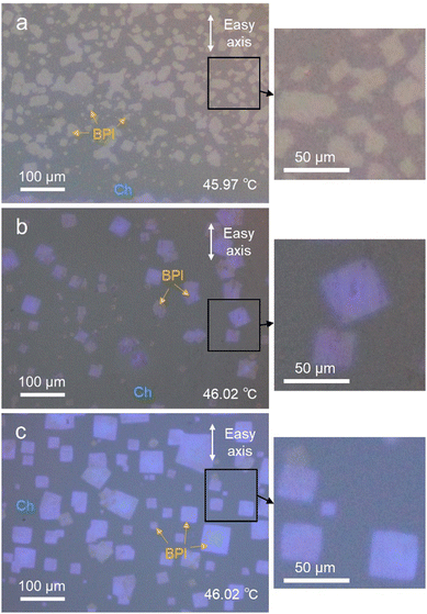
Fig. 1 shows BPI nucleation from a uniformly oriented Ch phase under the three alignment layer conditions. All the cells had a thickness of 5 μm and were filled with BPLC1. In the photoalignment cell without rubbing treatment, as shown in Fig. 1(a), nucleation occurred rapidly above the phase-transition temperature. Consequently, dense small BPI crystals were formed. Here, the average size of the crystals, which were not merged with neighboring crystals and existed independently, was evaluated using image analysis software (ImageJ, National Institutes of Health) and was 1.4 × 102 μm2. In contrast, in the cells rubbed on the photoalignment film in Fig. 1(b) and the cells rubbed on the polyimide film in Fig. 1(c), nucleation occurred at a low density, and the temperature at which each nucleation occurred varied. Thus, time and space were allowed for crystal growth, and each crystal was large, with average crystal sizes of 4.9 × 102 μm2 and 1.7 × 103 μm2 in Fig. 1(b) and (c), respectively. Moreover, the BPI crystals were square-shaped, as shown in the magnified POM images. The results revealed that it was not the alignment film material, but the rubbing process that affected the nucleation density of the BPI. Photoalignment is a non-contact process that utilizes the photoisomerization of azo dyes to align LCs without damaging the alignment film. In contrast, rubbing alignment is a contact process in which the alignment film is rubbed with a rayon cloth, which damages the alignment film. These scratches on the alignment film may have induced BPI nucleation. Our previous study on the Grandjean-Cano disclinations of Ch showed that an increase in the elastic energy around the disclinations promotes the Ch–BPI phase transition.31 As reported in previous studies, the locally enhanced elastic energy may have caused nucleation in the present study. That is, the scratches on the alignment film created by the rubbing process locally disrupt the Ch orientation, increasing the elastic energy and thereby inducing nucleation. The nucleation temperature varies slightly with the amount of elastic energy induced by scratches in the alignment film, resulting in a lower density of nucleation when the temperature is slowly increased. Furthermore, focusing on the crystal orientation, the cells with rubbed polyimide films in Fig. 1(c) have somewhat uniform crystal orientation, whereas the photoalignment films in (a) and (b) are more random. The force that fixes the LC orientation to the easy axis is expressed using the surface anchoring energy of the alignment film, and the polyimide film has a larger anchoring energy than the photoalignment film.32 Since the BP orientation is also affected by the anchoring energy,33 the crystal orientation in the polyimide film is more strongly determined than in the photoalignment film.Correlation between crystal axes and crystal shape
Using a rubbing cell with a thickness of 5 μm, we investigated the relationship between the crystal shape and the axis in BPI. Three types of BPLC materials were used in this study. Fig. 2 shows the POM images and Kossel diagrams obtained using an objective lens with 100× magnification. The observation areas for the POM images and Kossel diagrams were the same. The POM images show that the BPI crystals of all the materials grew in squares. In addition, for all the materials, the Kossel diagrams show four-fold symmetry lines, indicating that the (100) crystal plane is parallel to the substrate. The Kossel pattern reflects the crystal axes; the crystal axes corresponding to the observed Kossel diagrams are shown in Fig. 2. A comparison of the POM image with the Kossel diagram shows that the BPI crystal shape corresponds to the crystal axes and that the diagonal direction of the BPI crystal coincides with the [010] and [001] axes. Thus, this correspondence between the shape and the crystal axes suggests that the BPI crystal geometry is a rhombic dodecahedron. Schematic diagrams of the orientation of the rhombic dodecahedral BPI crystals are shown in Fig. 2(b). Note that this crystal geometry is valid only if the interaction at the Ch–BPI interface is the same in the direction perpendicular to the Ch helix as well as in the direction parallel to the Ch helix.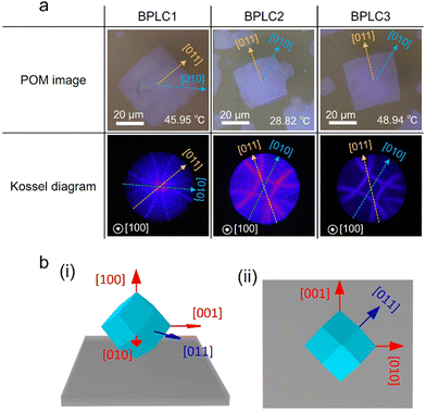 | ||
| Fig. 2 (a) POM images of BPI crystal and the corresponding Kossel diagrams. (b) Schematic of BPI crystal geometry in (i) perspective and (ii) top views. | ||
The crystal shape is induced by the anisotropy of the crystal growth rate.34 BPI crystals formed in the Ch–BPI phase transition are rhombic dodecahedral, indicating that the growth rate along the [010] and [001] axes is greater than that along the [011] and [0![[1 with combining macron]](https://www.rsc.org/images/entities/char_0031_0304.gif) 1] axes. Both Ch and BPI have periodic structures, but since Ch is uniformly oriented with respect to the substrate, the orientation state of Ch at the boundary between BPI and Ch does not change in the in-plane direction, that is, in the [010] or [011] axis direction. Therefore, the in-plane growth rate of BPI depends on the orientation state of each crystal plane of BPI. The crystal planes tend to be rough in the direction where the growth rate is slow,34 suggesting that the interfaces between the BPI (011) and (0
1] axes. Both Ch and BPI have periodic structures, but since Ch is uniformly oriented with respect to the substrate, the orientation state of Ch at the boundary between BPI and Ch does not change in the in-plane direction, that is, in the [010] or [011] axis direction. Therefore, the in-plane growth rate of BPI depends on the orientation state of each crystal plane of BPI. The crystal planes tend to be rough in the direction where the growth rate is slow,34 suggesting that the interfaces between the BPI (011) and (0![[1 with combining macron]](https://www.rsc.org/images/entities/char_0031_0304.gif) 1) planes and Ch are rough.
1) planes and Ch are rough.
Effect of the rubbing direction on crystal orientation
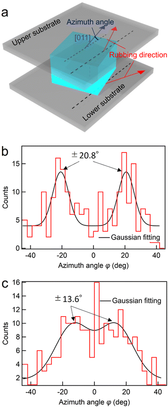
The in-plane orientation of the BPI crystals of BPLC1 was investigated using a rubbing cell. As shown in Fig. 3(a), the azimuth angle φ is defined as the tilt of the [011] axis from the rubbing direction. To measure the azimuth angle, five areas of 1.26 × 0.84 mm2 were taken from a single cell. From these, 200 crystal nuclei were randomly sampled, and the angle of the [011] axis was measured using Igor Pro (WaveMetrics). Fig. 3(b) shows the dispersion of the azimuth angle in a rubbing cell with a thickness of 5 μm. By fitting the distribution of these angles to a Gaussian function, we obtained a median value of −1.74°. Remarkably, the azimuth angle closely matched that of the easy axis, indicating a distinct anisotropy in the azimuthal orientation of BPI crystals with the (100) plane parallel to the substrate.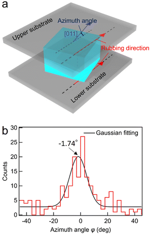 | ||
| Fig. 3 (a) Definition of azimuth angle for the BPI crystal. (b) Dispersion of azimuth angles in a rubbing cell with parallel rubbing directions. | ||
Previous studies have shown the critical role of the easy axis in defining the most stable azimuthal orientation of BPs in various orientation states.32,33 However, BPI transferred from uniformly oriented Ch in previous studies had a (100) plane parallel to the substrate as in this study, but its orientation was random, and anisotropy in azimuthal orientation has not been demonstrated.32 In contrast, our findings reveal anisotropy in the azimuthal orientation of BPI with the (100) plane parallel to the substrate. This anisotropy appears more pronounced in the current study compared to previous research, due to the slower rate of temperature increase, highlighting a more significant effect of the alignment film on BPI. However, the azimuthal orientation of BPI crystals was distributed around the easy axis, indicating an imperfect alignment. In typical LC phases such as the nematic phase, rubbing cells strongly anchor the director, enforcing a robust orientation towards the easy axis. Yet, BPI, with its macroscopically isotropic director orientation, exhibits a reduced match between its director orientation and the easy axis, consequently weakening the regulation over azimuthal orientation. Furthermore, considering the ordered structure of Ch, the orientation of BPI during the Ch–BPI phase transition is influenced not only by the easy axis but also by the orientation state of the Ch phase.32 This transition from an ordered phase introduces complexity into the BPI orientation mechanism, potentially diminishing the sensitivity of azimuthal orientation towards the easy axis. Therefore, the potentially weak orientability of BPI and the complex orientation mechanism may have contributed to the incomplete alignment of the azimuthal orientation.
Next, cells with different rubbing directions are fabricated on the upper and lower substrates, as shown in Fig. 4(a), and the azimuth angles are investigated in the same manner, as shown in Fig. 3. The upper and lower substrates were attached such that the rubbing directions deviated by 45°. The midpoint of these rubbing directions was used as a reference, and the tilt of the [011] axis was defined as the azimuth angle. Fig. 4(b) and (c) show the dispersion of the azimuth angle at cell thicknesses of 5 and 2 μm, respectively. The azimuthal angle distributions were fitted using a function that included two Gaussian functions. At a cell thickness of 5 μm, the distribution peaks were ±20.8°, which almost matched with that of the rubbing direction of ±22.5°. This finding suggests that the crystal orientation is determined by the influence of either the upper or lower substrate. In contrast, at a cell thickness of 2 μm, the peak of the distribution was ±13.6°, and the peak positions shifted closer from the rubbing direction of the upper and lower substrates. This result suggests that the crystal orientation is determined by the influence of both the upper and lower substrates.
Generally, in LC phases, the orientation can be changed by the rotation of molecules. However, because the molecules form a superstructure in the BPI, it is necessary to rotate the crystal itself to change the crystal orientation. At a cell thickness of 2 μm, the BPI crystal orientation was affected by the substrate opposite to the side on which nucleation occurred, whereas at a cell thickness of 5 μm, the BPI crystal orientation was hardly affected by the substrate opposite to the side chain, suggesting that the orientation of the BPI crystal was determined when the crystal size was smaller than 5 μm and that the crystal hardly rotates at larger sizes.
Effect of the easy axis on crystal growth
Fig. 1 shows that the crystal growth rate of BPI is anisotropic with respect to the crystal axis, and Fig. 2 shows that the easy axis affects crystal orientation. In this section, the effect of the easy axis on the crystal growth rate is discussed. The length in the direction parallel to the easy axis, l‖, and that perpendicular to it, l⊥, are defined, as shown in Fig. 5a, and the aspect ratio l‖/l⊥ is evaluated. The BPI crystal growth was observed using a 5 μm thick rubbing cell filled with BPLC1. One hundred crystals with the [011] crystal axis approximately parallel to the easy axis were sampled and analyzed for the aspect ratio. Fig. 5(b) shows a plot of the aspect ratio vs. the BPI crystal size, where the crystal size was set to l‖. The aspect ratio was distributed at approximately 1; this distribution was independent of the crystal size. In addition, as shown in Fig. 5(c), the distribution of the aspect ratios for crystals of all sizes is fitted using a Gaussian function. The peak of the Gaussian function was observed at 0.96, indicating that l‖ was slightly smaller than l⊥; however, the lengths were almost equal. Therefore, the effect of the easy axis on the crystal growth rate was minimal. Crystal growth is determined by the surface energy between the crystal and its surroundings, which includes the surface energy between BPI and the rubbed surface. However, because the BPI crystal shape is independent of the rubbing direction, the surface energy at the interface between BPI and Ch may be much larger than that at the interface between BPI and the rubbed surface. Furthermore, although the rubbing cell acts as a strong anchor for the typical LC phase, the force determining the BPI orientation is weak, as shown in Fig. 3, suggesting that the in-plane anisotropy of the energy at the interface between BPI and the rubbing surface is small. Therefore, the easy axis may not have affected the crystal growth rate of the BPI.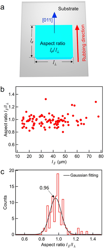 | ||
| Fig. 5 (a) Definition of the aspect ratio of the BPI crystal. (b) Relationship between the aspect ratio and the crystal size and (c) dispersion of the aspect ratio of a 5 μm thick rubbing cell. | ||
Control of the nucleation position
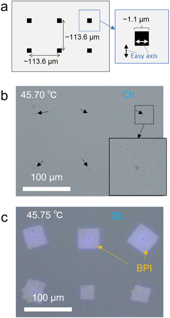
In this section, we demonstrate the control of the BPI nucleation position by intentionally disrupting the Ch orientation state based on the behavior in which scratches on the substrate surface are created by rubbing to induce BPI nucleation. As previously mentioned, the orientation of Ch changes at the scratches, which locally increases the elastic energy and induces nucleation. Thus, we patterned regions with different easy axis directions on the substrate surface via photoalignment, which intentionally caused an increase in the elastic energy of Ch owing to a change in the direction of the interfacial orientation at the boundaries of these regions. Using our photoalignment system, a local region of approximately 1.1 × 1.1 μm2 with a horizontal easy axis is fabricated within a region with a vertical easy axis, as shown in Fig. 6(a). The POM image of Ch oriented on this pattern with a cell thickness of 2 μm is shown in Fig. 6(b). Local regions with different easy axes appeared as black spots owing to the absorption anisotropy of the azo dye and the disordered orientation of Ch. Subsequently, the temperature in this cell was increased and stopped immediately after BPI nucleation to promote crystal growth. Fig. 6(c) shows the POM image obtained 15 min after the phase transition. The BPI crystals grew in a local region where the orientation was intentionally disrupted, indicating that the nucleation position could be controlled. Thus, the increase in elastic energy owing to the deformation of the surface orientation of Ch, applied by the alignment process, induces BPI nucleation. However, the crystals were not oriented precisely along the easy axis and had some distribution. This is similar to the BPI crystal orientation in the rubbed photoalignment cell in Fig. 1(b) and may be due to the small anchoring energy for the photoalignment film. Therefore, this technique allows the nucleation position and density to be controlled, which is crucial for controlling the crystal size, indicating that this technique is useful for obtaining large BPI crystals.Conclusions
In this study, the anisotropy of BPI crystal growth during the Ch–BPI phase transition from a uniformly oriented Ch phase was investigated. The BPI crystals grew in a square shape in a diagonal direction corresponding to the [010] crystal axis. This phenomenon was observed as a common feature of three materials with different elastic constants, which exhibits a typical behavior of BPI. Therefore, the crystal growth rate was anisotropic, with the crystal growth rate along the [010] axis being higher than that along the [011] axis. Furthermore, the BPI crystals exhibited an anisotropic orientation, with a tendency for their [011] axes to align with the easy axis, which indicated that BPI was influenced by the easy axis similar to other LC phases. However, the easy axis exhibited little impact on the crystal growth rate. Furthermore, BPI nucleation was induced by the disruption of the Ch orientation state by scratches on the alignment film. Based on this behavior, we demonstrated a technique for controlling the nucleation position by intentionally disrupting the Ch orientation via photoalignment patterning. This technique allows the nucleation position and density to be controlled, enabling the fabrication of large BPI crystals. This study focused on the anisotropic crystal growth of BPI, providing interesting insights into LC phase transitions and soft matter crystal growth. In addition, it offers techniques for the fabrication of large BPI crystals, contributing to the improvement of the electrical and optical performances of BPLC devices.Author contributions
K. N. performed the experiments and M. O. supervised this study.Conflicts of interest
There are no conflicts of interest to declare.Acknowledgements
We thank DIC Co. for providing the alignment agent. This work was partly supported by MEXT KAKENHI (JP23H02038) and a Grant-in-Aid for JSPS Fellows (23KJ1507).References
- D. C. Wright and N. D. Mermin, Rev. Mod. Phys., 1989, 61, 385–432 CrossRef CAS.
- H. Yoshida, K. Anucha, Y. Ogawa, Y. Kawata, M. Ozaki, J. Fukuda and H. Kikuchi, Phys. Rev. E, 2016, 94, 042703 CrossRef PubMed.
- Y. Hisakado, H. Kikuchi, T. Nagamura and T. Kajiyama, Adv. Mater., 2005, 17, 96–98 CrossRef CAS.
- H. Kikuchi, H. Higuchi, Y. Haseba and T. Iwata, SID Int. Symp. Dig. Tech. Pap., 2007, 38, 1737–1740 Search PubMed.
- Y. Sun, Y. Li, Y. Zhao, P. Li and H. Ma, J. Disp. Technol., 2014, 10, 484–487 Search PubMed.
- H. Kikuchi, Y. Haseba, S. Yamamoto, T. Iwata and H. Higuchi, SID Int. Symp. Dig. Tech. Pap., 2009, 40, 578 Search PubMed.
- H. Chen, Y.-F. Lan, C.-Y. Tsai and S.-T. Wu, Liq. Cryst., 2017, 44, 1124–1130 CrossRef CAS.
- R. M. Hyman, A. Lorenz, S. M. Morris and T. D. Wilkinson, Appl. Opt., 2014, 53, 6925 CrossRef PubMed.
- C. Sun and J. Lu, Sci. Rep., 2019, 9, 1–6 CrossRef PubMed.
- E. Oton, E. Netter, T. Nakano, Y. D.-Katayama and F. Inoue, Sci. Rep., 2017, 7, 44575 CrossRef CAS PubMed.
- F. Peng, Y.-H. Lee, Z. Luo and S.-T. Wu, Opt. Lett., 2015, 40, 5097 CrossRef CAS PubMed.
- M.-J. Lee, C.-H. Chang and W. Lee, Biomed. Opt. Express, 2017, 8, 1712 CrossRef CAS PubMed.
- R. Liao, X. Zhan, X. Xu, Y. Liu, F. Wang and D. Luo, Liq. Cryst., 2020, 47, 715–722 CrossRef CAS.
- S. Yokoyama, S. Mashiko, H. Kikuchi, K. Uchida and T. Nagamura, Adv. Mater., 2006, 18, 48–51 CrossRef CAS.
- J.-D. Lin, T.-Y. Wang, T.-S. Mo, S.-Y. Huang and C.-R. Lee, Sci. Rep., 2016, 6, 30407 CrossRef CAS PubMed.
- Y. Kawata, H. Yoshida, S. Tanaka, A. Konkanok, M. Ozaki and H. Kikuchi, Phys. Rev. E: Stat., Nonlinear, Soft Matter Phys., 2015, 91, 022503 CrossRef PubMed.
- P. Nayek, H. Jeong, S.-W. Kang, S. H. Lee, H.-S. Park, H. J. Lee, H. S. Kim and G.-D. Lee, J. Soc. Inf. Disp., 2012, 20, 318 CrossRef CAS.
- H.-S. Chen, Y.-H. Lin, C.-H. Wu, M. Chen and H.-K. Hsu, Opt. Mater. Express, 2012, 2, 1149 CrossRef CAS.
- S. Liu, I. Nys and K. Neyts, Adv. Opt. Mater., 2022, 10, 2200711 CrossRef CAS.
- J. A. Martínez-González, X. Li, M. Sadati, Y. Zhou, R. Zhang, P. F. Nealey and J. J. de Pablo, Nat. Commun., 2017, 8, 15854 CrossRef PubMed.
- E. Otón, P. Morawiak, K. Gaładyk, J. M. Otón and W. Piecek, Opt. Express, 2020, 28, 18202 CrossRef PubMed.
- K. Nakajima, Y. Tsukamoto, S. Mitsuhashi and M. Ozaki, Appl. Phys. Express, 2022, 15, 071007 CrossRef CAS.
- K. Nakajima, S. Mitsuhashi, S. Cho and M. Ozaki, ACS Appl. Mater. Interfaces, 2023, 15, 40054–40061 CrossRef CAS PubMed.
- Y. Chen and S.-T. Wu, Appl. Phys. Lett., 2013, 102, 171110 CrossRef.
- S. Cho, M. Takahashi, J. Fukuda, H. Yoshida and M. Ozaki, Commun. Mater., 2021, 2, 39 CrossRef CAS.
- C. W. Chen, C. T. Hou, C. C. Li, H. C. Jau, C. T. Wang, C. L. Hong, D. Y. Guo, C. Y. Wang, S. P. Chiang, T. J. Bunning, I. C. Khoo and T. H. Lin, Nat. Commun., 2017, 8, 1–8 CrossRef PubMed.
- R. Barbet-Massin, P. E. Cladis and P. Pieranski, Phys. Rev. A: At., Mol., Opt. Phys., 1984, 30, 1161–1164 CrossRef CAS.
- X. Li, J. A. Martínez-González, J. P. Hernández-Ortiz, A. Ramírez-Hernández, Y. Zhou, M. Sadati, R. Zhang, P. F. Nealey and J. J. de Pablo, Proc. Natl. Acad. Sci. U. S. A., 2017, 114, 10011–10016 CrossRef CAS PubMed.
- H. M. Jin, X. Li, J. A. Dolan, R. J. Kline, J. A. Martínez-González, J. Ren, C. Zhou, J. J. de Pablo and P. F. Nealey, Sci. Adv., 2020, 6, eaay5986 CrossRef CAS PubMed.
- O. Henrich, K. Stratford, D. Marenduzzo and M. E. Cates, Proc. Natl. Acad. Sci. U. S. A., 2010, 107, 13212–13215 CrossRef CAS PubMed.
- K. Nakajima, S. Mitsuhashi and M. Ozaki, Appl. Phys. Express, 2024, 17, 046002 CrossRef.
- M. Takahashi, T. Ohkawa, H. Yoshida, J. Fukuda, H. Kikuchi and M. Ozaki, J. Phys. D: Appl. Phys., 2018, 51, 104003 CrossRef.
- J. Fukuda and S. Žumer, Phys. Rev. Res., 2020, 2, 033407 CrossRef CAS.
- A. Kelly and K. M. Knowles, Crystallography and Crystal Defects, Wiley, 2012, pp. 391–433 Search PubMed.
Footnote |
| † Electronic supplementary information (ESI) available: Elastic constants of the host nematic LC materials used in BPLCs and phase transition temperatures of the BPLC materials. See DOI: https://doi.org/10.1039/d4sm00289j |
| This journal is © The Royal Society of Chemistry 2024 |

