 Open Access Article
Individual closed-loop control of micromotors by selective light actuation†
David P.
Rivas
,
Max
Sokolich
and
Sambeeta
Das
 *
*
Department of Mechanical Engineering, 130 Academy Street, Newark, DE, USA. E-mail: samdas@udel.edu
First published on 11th November 2024
Abstract
Control of individual micromotors within a group would allow for improved efficiency, greater ability to accomplish complex tasks, higher throughput, and increased adaptability. However, independent control of micromotors remains a significant challenge. Typical actuation techniques, such as chemical and magnetic, are uniform over the workspace and therefore cannot control one micromotor independently of the others. To address this challenge, we demonstrate a novel control method of applying a localized region of UV light that activates a single light-responsive TiO2 micromotor at a time. To achieve this, a digital micromirror device (DMD) was employed which is capable of highly precise localized illumination. To demonstrate this precise user-defined control, patterns of micromotors were created via selective actuation and magnetic steering. In addition, a closed-loop system was also developed which automates the guidance of individual micromotors to specified locations, illustrating the potential for more efficient and precise control of the micromotors.
Controlling a group of micromotors individually would significantly increase their ability to perform complex tasks efficiently and quickly, making such independent control critical for many potential applications.1,2 For example, spatially controlled delivery of signaling molecules in biomedical research,3 or the manipulation of micromotors into patterns or groupings for better maneuverability through difficult-to-navigate environments,4,5 would greatly benefit from the ability to control individual micromotors independently. One of the strategies that has been employed toward this end include the creation of special substrates that create localized forces. For example, a magnetic coil array embedded on a circuit board created localized magnetic fields,6 and, in another study, electrostatic anchoring pads acted to selectively stick microrobots to a surface.7 However, these approaches involve the use of special substrates that are impractical in many applications. Another method used optical tweezers to move one colloid at a time, although this requires the use of high intensity light that can damage biological organisms.8 Additionally, optical tweezers produce weak forces, require specific types of colloids, and, due to the requirement of focusing the beam into a small area, operate in a small workspace.2 Other strategies include the creation of sub-millimeter robots that respond to oscillating magnetic fields at different resonant frequencies.9 This enables independent control of the microrobots by changing the frequency of magnetic actuation. However, such methods require the manufacturing of complex robot designs. Other studies have utilized microrobots of various shapes or sizes to capitalize on differences in their magnetic rolling or swimming speeds.10–12 However, this requires sophisticated algorithms and is inefficient. Another design took advantage of acoustic resonance of microrobots that contain microbubbles to actuate microrobots within a certain frequency band.13 Creating a large number of swimmers with different acoustic resonant frequencies is difficult, however. In addition, the resonant frequency can be hard to know a priori and can change somewhat over time. Lasers have been used to create and manipulate multiple microbubbles independently,14 although generating the bubbles requires strong laser intensity and are confined to the 2D surface.
To overcome these challenges, we created a new approach to individual control by using a digital micromirror device (DMD) to produce a localized “spotlight” that is small enough to actuate only one micromotor at a time, and we designed a closed-loop system to automate their control. The light spotlights are used to actuate individual titanium dioxide magnetic Janus micromotors and magnetically steer them to a desired location. Our DMD system produces a light intensity around 500 mW cm−2, which is much less than optical tweezers, for example, which can be 106 times greater.15 The independent control we attain is demonstrated by creating patterns of the micromotors on the glass surface. We also developed a closed-loop control system to automatically guide specific micromotors to user-defined locations. Therefore, this work demonstrates a new method to selectively control the motion of micromotors independently and in an automated fashion, which addresses a major challenge in the microrobotic field and provides a step towards realizing more efficient and effective control of micromotors for physics and biomedical research, as well as for real-world applications.
Details of the micromotor fabrication are given in the ESI.† Briefly, TiO2 homogeneous spherical microspheres of two different sizes were made. To make the smaller spheres (average diameter of 1.3 μm with a standard deviation of 0.3 μm), a solvent extraction/evaporation method was used following a previously documented procedure.16 To create larger particles (average diameter 4.3 μm with a standard deviation of 1.4 μm), a solvothermal method was used following the procedure in ref. 17. Both types of particles were annealed in a furnace at 400 °C for two hours to create the anatase phase. The particles were then suspended in ethanol and spread onto a glass slide. After the ethanol evaporated, the slides of the smaller particles were coated with 20 nm each of Ni/Fe alloy, Pt, and Ag by electron-beam evaporation, as described previously.18 The larger particles were coated with a 20 nm layer of Ni. The Ni/Fe and Ni coating on the microrobots gives them a magnetic moment, allowing for them to be magnetically steered. An SEM image of one of the resulting Janus particles is given in the ESI.†
The micromotors move when illuminated by UV light which is thought to be due to a self-electrophoretic propulsion mechanism, as described in previous work.19,20 The UV light causes electrons on the non-coated TiO2 side of the micromotor to move into the conduction band of the semiconductor material. These electrons then migrate to the metal coated hemisphere of the micromotor. Oxidation of water and hydrogen peroxide at the TiO2 side and reduction of protons at the metal side leads to a flow of positive charges from the TiO2 side towards the metal side of the micromotors. This results in a self-produced electric field that generates a movement of the negatively charged micromotors with the TiO2 side leading.
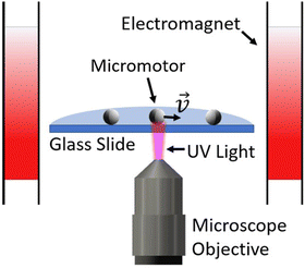
UV light at 365 nm was produced by a digital micromirror device (DMD) (Mightex Polygon Pattern Illuminator) which illuminates the sample from below. The device provides precise spatial and temporal control of light with micron scale resolution. Mightex Polyscan software allows for any 2D binary image to be converted into a light pattern within a rectangular region in the field of view. Magnetic fields were supplied with a three-axis electromagnetic system,21 which produces uniform magnetic fields in any direction. The magnetic fields create a torque on the microrobot which acts to align their magnetic moment with the applied field, enabling them to be magnetically steered. Micromotors suspended in DI water were added to a 1.5 mL plastic tube to which hydrogen peroxide was added to a concentration of 3–15%. The solution was mixed and then a drop was placed on a coverslip on the microscope. Samples were observed using a Zeiss Axiovert 200 microscope with a 50× objective (Zeiss epiplan-neofluar 50×/0.8) and videos were recorded with an Amscope MU903-GS microscope digital camera. A schematic of the experimental setup is shown in Fig. 1.
When illuminated with UV light, the micromotors become motile and their direction of motion is generally stochastic.18 With a magnetic field applied, the micromotors can be steered in desired directions. The speed of the larger micromotors as a function of light intensity is shown in Fig. 2 (the speed of the smaller micromotors has been quantified previously18 and is shown in the ESI†). The data in the plot was taken when applying a rectangular region of light of about 400 × 230 μm in size. With a small disk of light applied, the micromotors tended to move somewhat more slowly compared to the case of maximal illumination. To quantify this, we measured the speed of micromotors that were illuminated by a disk of radius 13 μm and compared this to their speed when illuminated by a full rectangle. We found that the ratio of speeds of full illumination to the localized disk of light was 1.48 ± 0.31 and 1.38 ± 0.14 for the large and small particles, respectively. We are unsure of the reason for the difference in speeds, although one possible reason could be due to the micromotors not always residing in the exact center of the disk. The light intensity may be somewhat weaker at the edges of the disk compared to the center, causing a lower speed. A more in depth discussion of this is given in the ESI.†
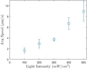 | ||
| Fig. 2 The average speed of the larger TiO2 micromotors as a function of light intensity at a hydrogen peroxide concentration of 15%. Error bars represent standard error of the mean. | ||
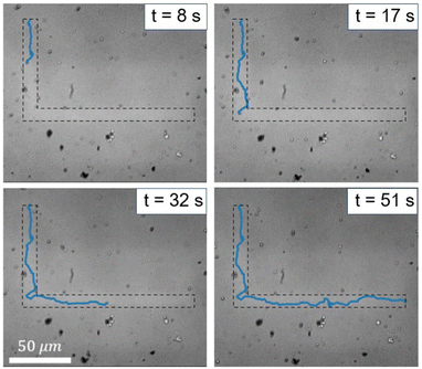
We utilized the DMD system's ability to apply light in any spatial pattern to only illuminate a single micromotor at a time. As an initial example of the selective illumination capabilities of the DMD system, we applied a band of light (a “light highway”) in an “L” shape (see Fig. 3 and Video S1, ESI†). Micromotors outside this region undergo slow diffusive motion (see Fig. S3 in the ESI†) while those inside the illuminated region self-propel and can be steered using magnetic fields to stay within the region.
Further control was achieved by illuminating individual micromotors with a dynamic light “spotlight” that could be moved such that it tracked the location of the micromotor. Manual control of the location of the spotlight could be achieved in the DMD software.
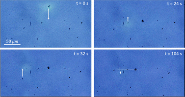
To demonstrate the control of multiple micromotors independently, we created patterns of the larger sized micromotors, namely a square and a horizontal line (see Video S2, ESI†). The horizontal line pattern is shown in Fig. 4. The spotlight was moved to illuminate the selected micromotor while the others underwent slow Brownian diffusion. Magnetic fields were applied using a joystick to steer the motile micromotor to its final location at which time a different micromotor was illuminated and steered in a similar fashion. This was repeated until the pattern was achieved.
Additionally, we made the micromotor control fully automated. Previous reports have demonstrated automated magnetic steering of active micromotors using closed-loop control algorithms and micromotor tracking,22–25 however this is the first demonstration of closed-loop control using both light and magnetic actuation. The closed-loop control system works by tracking a micromotor that the user selects and translating the UV spotlight to follow the micromotor. Magnetic steering guides the micromotor to the user-defined goal position. An example of the closed-loop control process is shown in Fig. 5 and Video S3 (ESI†). Details of our magnetic steering algorithm can be found in a previous report23 and in the ESI.† Briefly, the code evaluates the average direction of motion of the micromotor over a short time period and determines the angular offset between this and the applied field. It then updates the orientation of the field to compensate for this offset, while also re-orientating the field in order to direct the micromotor toward the target location. The light following was done by continuously shifting the location of applied light to follow the trajectory of the micromotor using custom python code. More details are given in the ESI.†Fig. 5 shows the automated maneuvering of micromotors (dashed circles represent the edge of the light disk) to create a triangular shape. We used the larger particles in cases in which we applied closed loop control control since they tended to move in a more consistent and controllable manner, while also being easier to track due to their larger size.
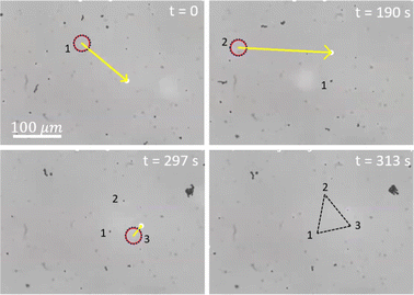 | ||
| Fig. 5 A series of images showing the creation of a triangular pattern of micromotors using automated closed-loop control (also see Video S3, ESI†). To from the pattern, the final desired location of each micromotor was selected using our custom python interface and the spotlight (highlighted by a dashed circle to act as a visual aid) was automatically translated to follow the trajectory of the micromotor while also supplying the appropriate magnetic fields to guide it to the desired location. Three micromotors were maneuvered to their final locations in a series, forming the triangular shape. The selected micromotor is highlighted by a red circle. The yellow arrows point to the desired final location of the micromotor. We used the larger TiO2 micromotors in this experiment and the concentration of hydrogen peroxide was 3%. The light intensity was approximately 500 mW cm−2 and the magnetic field strength was approximately 5 mT. | ||
The ability to control micromotors independently is a major objective in microrobotics and opens up many new ways to apply the robots to a host of important applications. In this paper, we have shown that independent control is achievable using a localized region of applied light from a DMD system. Patterns of micromotors were created by utilizing this selective actuation, demonstrating an advantage of independent control over global actuation. We have also demonstrated automatic computerized control of the light-actuated micromotors that integrates their light and magnetic responsiveness. Overall, the use of a DMD system for localized UV illumination and selective control of light-actuated micromotors could be a promising method to employ micromotors in a variety of applications where such independent control is required. The DMD system produced relatively low intensity light which is compatible with future biomedical applications. However, these micromotors still require the use of hydrogen peroxide fuel for improving their motility. There has been reports of light-activated micromotors moving in water alone without the need for toxic fuel.16,19 Therefore, future work is needed to apply non-toxic actuated micromotors in the body or with living organisms, and in particular to create faster and more powerful micromotors which could be essential to certain applications. Our system requires the use of controllable magnetic fields to steer the micromotors. Due to the long working distance of magnetic fields produced by electromagnetic coils, this is not expected to limit its application in most situations, however. Light actuation is limited to semi-transparent systems, making it difficult to employ in many biomedical settings. However, these micromotors could be promising candidates for applications in lab-on-chip devices or other semi-transparent systems like the eye.
Author contributions
D. P. R. and M. S. conducted experiments and developed the computer code. D. P. R. analyzed the data and wrote the manuscript. S. D. acquired funding and supervised the project. D. P. R., M. S., and S. D. conceptualized the project and edited the manuscript.Data availability
The data that support the findings of this study are available from the corresponding author, S. D., upon reasonable request.Conflicts of interest
There are no conflicts to declare.Acknowledgements
We would like to acknowledge Zameer Shah for assisting with the particle synthesis. This work was supported by the National Science Foundation under grant GCR 2218980, CPS 2234869, and the National Health Institute under grant 1R35GM147451. M. S. is supported by the NSF Graduate Research fellowship 1940700.Notes and references
- M. Wang, T. Wu, R. Liu, Z. Zhang and J. Liu, Engineering, 2023, 24, 21–38 CrossRef.
- S. Chowdhury, W. Jing and D. J. Cappelleri, J. Micro-Bio Robot., 2015, 10, 1–11 CrossRef.
- S. Das, E. E. Hunter, N. A. DeLateur, E. B. Steager, R. Weiss and V. Kumar, 2018 International Conference on Manipulation, Automation and Robotics at Small Scales (MARSS), 2018, pp. 1-5.
- G. Gardi, S. Ceron, W. Wang, K. Petersen and M. Sitti, Nat. Commun., 2022, 13, 2239 CrossRef CAS PubMed.
- J. Yu, L. Yang, X. Du, H. Chen, T. Xu and L. Zhang, IEEE Trans. Robot., 2022, 38, 1552–1570 Search PubMed.
- B. V. Johnson, S. Chowdhury and D. J. Cappelleri, IEEE/ASME Trans. Mech., 2020, 25, 526–534 Search PubMed.
- C. Pawashe, S. Floyd and M. Sitti, Appl. Phys. Lett., 2009, 94, 164108 CrossRef.
- D. Choudhary, A. Mossa, M. Jadhav and C. Cecconi, Biomolecules, 2019, 9, 23 CrossRef PubMed.
- D. R. Frutiger, K. Vollmers, B. E. Kratochvil and B. J. Nelson, Int. J. Robot. Res., 2010, 29, 613–636 CrossRef.
- E. Diller, S. Floyd, C. Pawashe and M. Sitti, IEEE Trans. Robot., 2012, 28, 172–182 Search PubMed.
- U. Kei Cheang, K. Lee, A. A. Julius and M. J. Kim, Appl. Phys. Lett., 2014, 105, 083705 CrossRef.
- I. S. M. Khalil, A. F. Tabak, Y. Hamed, M. Tawakol, A. Klingner, N. E. Gohary, B. Mizaikoff and M. Sitti, IEEE Robot. Autom. Lett., 2018, 3, 1703–1710 Search PubMed.
- J. M. McNeill, N. Nama, J. M. Braxton and T. E. Mallouk, ACS Nano, 2020, 14, 7520–7528 CrossRef CAS PubMed.
- M. A. Rahman, J. Cheng, Z. Wang and A. T. Ohta, Sci. Rep., 2017, 7, 3278 CrossRef PubMed.
- E. J. Peterman, F. Gittes and C. F. Schmidt, Biophys. J., 2003, 84, 1308–1316 CrossRef CAS.
- R. Dong, Q. Zhang, W. Gao, A. Pei and B. Ren, ACS Nano, 2016, 10, 839–844 CrossRef CAS.
- C. Chen, F. Mou, L. Xu, S. Wang, J. Guan, Z. Feng, Q. Wang, L. Kong, W. Li, J. Wang and Q. Zhang, Adv. Mater., 2017, 29, 1603374 CrossRef.
- B. Wu, D. P. Rivas and S. Das, Mater. Adv., 2024, 5, 1875–1879 RSC.
- T. Maric, M. Z. M. Nasir, R. D. Webster and M. Pumera, Adv. Funct. Mater., 2020, 30, 1908614 CrossRef CAS.
- Z. Xiao, J. Chen, S. Duan, X. Lv, J. Wang, X. Ma, J. Tang and W. Wang, Chem. Commun., 2020, 56, 4728–4731 RSC.
- M. Sokolich, D. Rivas, Y. Yang, M. Duey and S. Das, MethodsX, 2023, 10, 102171 CrossRef PubMed.
- J. Jiang, Z. Yang, A. Ferreira and L. Zhang, Adv. Intell. Syst., 2022, 4, 2100279 CrossRef.
- M. Sokolich, D. Rivas, Z. H. Shah and S. Das, MRS Adv., 2023, 8, 1005–1009 CrossRef CAS.
- X. Wu, J. Liu, C. Huang, M. Su and T. Xu, IEEE Trans. Autom. Sci. Eng., 2020, 17, 823–832 Search PubMed.
- I. S. M. Khalil, V. Magdanz, S. Sanchez, O. G. Schmidt and S. Misra, IEEE Trans. Robot., 2014, 30, 49–58 Search PubMed.
Footnote |
| † Electronic supplementary information (ESI) available. See DOI: https://doi.org/10.1039/d4sm00810c |
| This journal is © The Royal Society of Chemistry 2024 |

