
 Open Access Article
 This Open Access Article is licensed under a
 Creative Commons Attribution 3.0 Unported Licence
How smectic-A and smectic-C liquid crystals resolve confinement-induced frustration in spherical shells†
Anjali
Sharma‡
a,
Mitchell
Magrini‡
b,
Yucen
Han‡
 c,
David M.
Walba
b,
Apala
Majumdar
c and
Jan P. F.
Lagerwall
*a
c,
David M.
Walba
b,
Apala
Majumdar
c and
Jan P. F.
Lagerwall
*a
aUniversity of Luxembourg, Department of Physics & Materials Science, Luxembourg. E-mail: jan.lagerwall@lcsoftmatter.com
bUniversity of Colorado at Boulder, Chemistry 215 UCB Boulder, CO 80309-0215, USA
cUniversity of Strathclyde, Department of Mathematics and Statistics, Glasgow, UK
First published on 22nd November 2024
Abstract
The layered structure of smectic liquid crystals cannot develop unobstructed when confined to spherical shells with layers extending in the radial direction, since the available cross section area increases from the inside to the outside of the shell yet the number and thickness of layers must be constant. For smectic-A (SmA) liquid crystals, with the layer normal m parallel to the director n, the frustration breaks up the texture into spherical lune domains with twist deformations of alternating sense, overlaid with a herringbone-like secondary modulation and mediated via localized bend regions where the boundary conditions are violated. The SmC phase has more degrees of freedom to resolve the frustration thanks to its non-zero tilt angle τ between n and m, but its response to tangential shell confinement was never studied. We show experimentally and theoretically that the lunes in shells undergoing a SmA–SmC transition become twice as wide and half as many and they lose the secondary modulation, adopting a configuration with no layer twist but uniform layer bend if τ reaches a large enough value. Our study expands our understanding of how smectics respond to spherical confinement and it opens new soft matter research opportunities, given the rich diversity of phases with SmC-like symmetry, including chiral and spontaneously polarized phases.
1 Introduction
The study of liquid crystals (LCs) in a spherical geometry has been an emergent field in recent decades, originally motivated by an interest in making artificial colloids that replicate recognition mechanisms present in biology1–4 and building on a collective understanding of smart responsiveness from the study of LCs in a more traditionally used flat geometry.3,5,6 LCs and long-range ordered polymers in droplets were of significant interest due to the topological requirements of the spherical geometry dictating a non-zero defect configuration,4,7–11 potential applications of self-assembling systems of higher order,2,7 and the exclusion of non-LC material to the defect sites.6,12,13 Of more recent interest has been the study of LC shells, i.e., a thin layer of LC around a droplet of an immiscible isotropic liquid (often water-based) and surrounded by the same or different liquid (Fig. 1(a)). The configuration of the director field n(r) (describing the average orientation of the molecular long axis) is controlled first via the boundary conditions, tangential (planar) or normal (homeotropic) depending on the interactions between the isotropic liquids and LC mesogens,14 further tuning possible using amphiphilic additives, over each entire interface15 or locally.16 A yet more powerful tool is to vary the type of LC phase. | ||
Fig. 1 (a) Schematic of an LC shell with inner radius R, average thickness h and outer radius Ro. Black lines are in the page plane whereas orange lines illustrate three adjacent lunes, coming out of the page. The purple vector ![[r with combining circumflex]](https://www.rsc.org/images/entities/i_char_0072_0302.gif) , pointing to an arbitrary point on the shell surface above the paper plane, defines the polar angle θ and the azimuthal angle ϕ of the spherical coordinate system (er,eθ,eϕ). The maximum lune width, at θ = π/2, is we (index ‘e’ for ‘equator’). (b) An example of a SmA shell with spherical lunes and the secondary herringbone-like modulation, observed in POM. The inset shows a magnification of the area within the dashed white circle, to better visualize the secondary modulation. (c) Illustration of the undulating layer twist (ignoring secondary modulation) across three adjacent lunes in a SmA shell at θ = π/2. The smectic layer boundaries on the shell inside are horizontal, drawn as black lines with the SmA layer thickness dA as separation along eθ. The boundaries on the outside, drawn red, are maximally rotated by magnitude β (exaggerated for clarity) yielding a greater separation dθo along eθ. At lune boundaries (green dashed lines), the twist goes to zero and instead the layers bend by an angle ±γ. The bending direction is indicated with blue arrows. The azimuthal angle ϕ is defined zero at the center of the first lune and ϕA at the first lune boundary. , pointing to an arbitrary point on the shell surface above the paper plane, defines the polar angle θ and the azimuthal angle ϕ of the spherical coordinate system (er,eθ,eϕ). The maximum lune width, at θ = π/2, is we (index ‘e’ for ‘equator’). (b) An example of a SmA shell with spherical lunes and the secondary herringbone-like modulation, observed in POM. The inset shows a magnification of the area within the dashed white circle, to better visualize the secondary modulation. (c) Illustration of the undulating layer twist (ignoring secondary modulation) across three adjacent lunes in a SmA shell at θ = π/2. The smectic layer boundaries on the shell inside are horizontal, drawn as black lines with the SmA layer thickness dA as separation along eθ. The boundaries on the outside, drawn red, are maximally rotated by magnitude β (exaggerated for clarity) yielding a greater separation dθo along eθ. At lune boundaries (green dashed lines), the twist goes to zero and instead the layers bend by an angle ±γ. The bending direction is indicated with blue arrows. The azimuthal angle ϕ is defined zero at the center of the first lune and ϕA at the first lune boundary. | ||
Initially the study focused on the nematic (N) LC phase17,18—exhibiting long-range orientational but only short-range positional order—as a platform for elucidating the dynamics and overall configuration of topological defects within the shell.19–21 A significantly more complex n(r) was encountered when cooling tangential-aligned shells from the N to a smectic-A (SmA) phase.22–26 SmA adds long-range positional order along one dimension by organizing the molecules into layers, the smectic layer normal m being along the director, m||n. With tangential boundary conditions for n also m is tangent to the shell interfaces, hence the smectic layers extend in the radial direction er. The intriguing textures encountered (Fig. 1(b)) reflect the frustration arising when the layers find themselves needing to span a distance along the original n direction (eθ in Fig. 1) that continuously increases from the shell inside to the outside (see Section 3.2). This is in apparent conflict with the requirement to maintain a constant SmA layer thickness dA, which is fixed by the effective molecule length and the degree of orientational order.27
To avoid costly layer dislocations, the SmA phase forms spherical lune-shaped domains in which the n||m couple undulates in a zigzag-like fashion. The lunes get thinner the larger or thinner the shell, the maximum lune width scaling linearly with the ratio of shell thickness to radius.28,29 Liang et al. proposed22,24 that the layers twist about er, with opposite handedness in adjacent lunes, i.e., n||m would rotate increasingly as we move outwards to accommodate the increasing length along eθ, see Fig. 1(c). Lopez-Leon argued against such a twist with the argument that it would violate the tangential boundary conditions.23,25 We do not see that this is the case, since smectic layers behave like two-dimensional liquids; similar to the twisted structure in a chiral nematic phase or twisted nematic display, n can be everywhere perpendicular to the twist axis, thus in planes parallel to the shell boundaries. We thus consider the model with twisted lunes in SmA to be well motivated and will build on this in the following.
Shortly after the lune formation, an additional much smaller scale herringbone-like dark-bright pattern develops, indicating a secondary modulation, and for thick shells even a tertiary modulation can be recognized.29 Liang et al. conjectured22 that this is because the rotation of m away from eθ, increasing in magnitude along er, means that the spherical curvature along each new m direction causes the same type of problem of the effective layer distance needing to increase along er. This new frustration created by the original layer twist would trigger a secondary, eventually also a tertiary, layer undulation on smaller scale within each lune, qualitatively explaining the new pattern.
To allow the alternation of twisting sense without introducing dislocations, the twist must go to zero locally at lune boundaries. Here, the layers must instead bend, alternatingly upwards and downwards, to accommodate the increasing distance along eθ from the shell inside to its outside.13 In contrast to the twisting, this bend in m comes at the cost of violating the tangential boundary condition at the shell outside since n||m in SmA. A constant layer tilt, without bend, would not resolve the problem, because it would increase the effective layer distance along eθ equally from the inside to the outside.
The modulated external surfaces of tangential-aligned SmA shells can be visualized with high magnification by scanning electron microscopy (SEM) by polymerizing reactive LC molecules in the shells, the resulting polymer network being templated by n(r), see Fig. 5 in ref. 30 In addition to showing a zigzag pattern reflecting the alternation in n||m on the shell outside, the SEM images also suggest a topographical modulation, where the center of each lune bulges out with respect to the edges. This may be a result of the bend localized to the lune edges.
SmA is the most common of a large series of smectic phases,27 another important variant being the basic SmC phase in which n is tilted by an angle τ with respect to m, see Fig. 2(a) and (b).§ The SmA–SmC transition is often second order, the tilt angle increasing non-linearly upon cooling from τ = 0 at the transition, where SmA and SmC are thus degenerate, toward a saturation value in the range 15–30°, see Fig. 2(a). In contrast to the tilt magnitude τ, which is well-defined at any temperature, the tilt direction, given by the local azimuthal angle φ, does not affect the free energy of a bulk SmC phase,31 hence any φ is equally probable in the absence of boundaries. Only gradients in φ enter the free energy as elastic contributions. These are small for reasonable gradients, as evidenced by nearly 180° changes in φ developing spontaneously across samples as thin as 1.5 μm.32 The freedom to tilt in any direction, but at a fixed magnitude, defines the SmC tilt cone, illustrated in Fig. 2(b).
 | ||
| Fig. 2 (a) Illustration of how the smectic layer thickness d shrinks on cooling from SmA (left, dA) to SmC (dC < dA), as τ increases. For τ = 5° and τ = 15° corresponding reduced temperatures Tr exist for the LC mixture used in this study, whereas τ = 30° is beyond its saturation. (b) The SmC tilt cone, drawn for τ = 30° and n pointing out of the paper plane along a direction φ from the left-side cross section. (c) Illustration of how a SmC phase with sufficiently large τ can resolve the frustration of increasing surface area from the shell inside (right) to the shell outside (left) by bending the layers and rotating n (blue) an angle φ = ±90° around the surface of the tilt cone; n is in the paper plane at the outside but tilts out of this plane on the inside. Black dashed lines indicate boundaries of layers bending upwards by an angle +γ, and brown dashed lines show the case for downward bend by −γ. | ||
The non-zero τ normally implies that the layers shrink in the SmC phase (Fig. 2(a)), because the average molecule orientation is no longer along m. This shrinkage means that SmC actually offers some interesting alternative solutions to relieve the frustration of smectics confined to spherical shells. In principle, the SmC phase could decrease τ from a maximum value at the inside to a minimum value at the outside, thereby achieving the required increase in layer thickness. However, since a change in τ from the equilibrium value comes at a significant free energy cost, a more likely scenario is that the phase utilizes the freedom in φ and lets n rotate around the tilt cone, at constant τ, bending the layers such that the projection of the layer thickness along the original n direction increases from inside to outside, as required by the non-zero shell thickness, see Fig. 2(c).
Spherically curved SmC phases were studied by Stannarius and co-workers on millimeter scale in the form of free-standing air-surrounded bubbles,33,34 and on the sub-millimeter scale in the form of water-surrounded shells once.26 In these studies, the behavior in SmC was compared to that in a SmA phase at higher temperatures, but the smectic layers were oriented in concentric geometry with radial m as ensured by imposing normal boundary conditions on n. Here we present the first experimental investigation and detailed theoretical analysis of the SmA–SmC phase transition in water-surrounded sub-millimeter shells with tangential alignment, focusing particularly on how the lunes formed in SmA transform upon cooling through the SmC phase. We find that n(r) undergoes a significant rearrangement, leaving half as many lunes that are twice as wide in the stable room temperature SmC shells. Moreover, the secondary herringbone-like modulation disappears. We postulate that these changes reflect the new way of responding to the constraints of spherical shell confinement enabled by the SmC structure, smoothly varying φ from the inside to the outside of the shell, replacing energetically costly layer twist with low-cost layer bend.
2 Methods and materials
The majority of LC shell studies were conducted with the popular cyanobiphenyl mesogens 5CB and 8CB, exceptionally suitable for LC shell production.30 However, their phase sequences lack SmC and thus cannot be used here. Instead, we use an equal mass mixture of 2-(4-hexyloxyphenyl)-5-octylpyrimidine (6OPhPy8) and 2-(4-octyloxyphenyl)-5-octylpyrimidine (8OPhPy8), Fig. 3(a) (Synthon, Germany). This mixture, also used in the earlier studies of normal-aligned shells26 and bubbles,33,34 exhibits a convenient phase sequence with a SmC phase at room temperature. On cooling from isotropic, first the N phase forms at ∼67.9 °C, followed by SmA at ∼59.8 °C, and then SmC takes over at TAC = 49.7 °C. While the two former transitions are first order and thus take place over a small temperature range, the SmA–SmC transition is nearly second order,26 exhibiting no coexistence and having a well-defined transition temperature, despite the LC being a mixture. We will for convenience often take TAC as reference and define a reduced temperature Tr = T − TAC.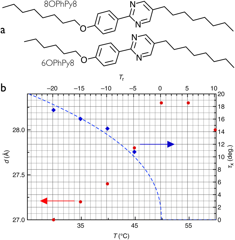 | ||
| Fig. 3 (a) Chemical structures of 8OPhPy8 and 6OPhPy8. (b) Smectic layer thickness d (left y-axis) and the x-ray tilt angle τx (right y-axis) as a function of temperature T (lower x-axis) or reduced temperature Tr with respect to the SmA–SmC transition temperature (upper x-axis) of the LC mixture used in the study. The grid refers to Tr and τx. Data are re-plotted from.35 The dashed curve is a fit to the experimental τx values of the function τx = τ′(TAC − T)a, where TAC is the SmA-C transition temperature (all temperatures are given in Kelvin) and τ′ is a hypothetical saturation tilt. The fitting yields TAC = 49.9 °C and a = 0.44. | ||
There are two standard methods to determine τ experimentally:27 POM investigations give the ‘optical tilt angle’ τo, while X-ray measurements of the smectic layer thickness yield the ‘X-ray tilt angle’ τx, from dC(T) = dA![[thin space (1/6-em)]](https://www.rsc.org/images/entities/char_2009.gif) cosτx,27 see Fig. 2(a). Here dC(T) is the temperature-dependent layer thickness in the SmC phase and dA is the thickness at the SmA–SmC transition. Generally τo > τx.27 For the discussion in this paper, τx is the relevant tilt angle and we thus use X-ray data published by Enz35 to establish τ = τx, as shown in Fig. 3(b).
cosτx,27 see Fig. 2(a). Here dC(T) is the temperature-dependent layer thickness in the SmC phase and dA is the thickness at the SmA–SmC transition. Generally τo > τx.27 For the discussion in this paper, τx is the relevant tilt angle and we thus use X-ray data published by Enz35 to establish τ = τx, as shown in Fig. 3(b).
We produce LC shells using a microfluidic system following the classic flow focusing design of Utada et al.36 (see that paper for the principles), in which two cylindrical capillaries are nested from two sides within a capillary with square cross section, the cylindrical capillaries serving as in- and outlet, respectively. The inlet is tapered to a small orifice diameter of about 60 μm while the outlet has been blunted to an orifice diameter of about 250 μm. The inner width of the rectangular capillary and the outer diameter of the cylindrical capillaries are equal, to align all capillaries and to ensure uniform flow when the device is in use. As isotropic inner and continuous phases we use a solution of 1 wt% poly(vinyl alcohol) (PVA, Mw = 13–23 kg mol−1, 87–89% hydrolyzed, Sigma-Aldrich) in deionized water (Sartorius arium pro-DI, resistivity 18 MΩ cm−1). Such a solution imposes tangential boundary conditions for n with LCs formed by aromatic mesogens,14 as in our mixture.
During shell production, we maintain the microfluidic device and all three liquid reservoirs at 70–72 °C to keep the LC mixture in the isotropic phase. This is ensured by contact heaters, an infrared lamp directed to the transfer tubes connecting reservoirs and microfluidic device, as well as occasional local use of a heat gun. Flow rates are adjusted using a computer-controlled pneumatic microfluidic flow control unit (Fluigent MFCS) paired with septum-capped vials. The LC shells are harvested as an aqueous suspension into a collection bath maintained at 35 °C. For microscopic analysis of the shells, suspensions are filled by capillary action into flat glass capillaries, sealing the openings and simultanouesly anchoring them to glass slides with epoxy resin. A capillary can then be placed inside of a heating stage (Linkam T95-PE) mounted on a POM (Olympus BX-51).
Due to density mismatch between the LC and the internal aqueous phase forming the inner droplet, the latter floats to the top at high temperatures, making the shell thinnest at the top and thickest at the bottom. This asymmetry is small in the shells studied here, hence we ignore it, approximating the shells as spherically symmetric with a constant thickness h. Experimentally, the shells typically have an inner radius R ≈ 120 μm and an average thickness h ≈ 5 μm.
3 Results and discussion
3.1 Experimental investigation of the textural development during the SmA–SmC transition
Because of the large temperature difference between the microfluidic shell production setup and the collection bath, the shells are quench cooled extremely rapidly through the N, SmA and the high-temperature region of the SmC phase, starting from isotropic disorder, when they are collected. This leads to a non-equilibrium SmC texture rich in defects in the pristine shells that does not lend itself well to analysis, see Fig. S1 in the ESI.† To anneal the shells and remove surplus defects they must be heated to the nematic phase, retained there for some minutes, and then cooled down to the smectic temperature range at a rate that preferably allows the LC to adjust n(r) to each new equilibrium configuration as the temperature changes.The equilibrium n(r) configuration in tangential-aligned SmA shells has been well studied, theoretically37–39 and experimentally using 8CB shells.22,23,25,39,40 It can be reached in experiments only by cooling very slowly from the N phase, at about −0.01 °C min−1, allowing n(r) to respond to the rapid divergence of the elastic constants for twist (K2) and bend (K3) upon approaching the N–SmA transition (explained in Section 3.2). This yields a configuration where four +1/2 defects distribute symmetrically on a great circle of the shell, with two sets of orthogonal lune domains extending from defect 1 to 3 (numbered sequentially along the great circle) on one side and from defect 2 to 4 on the opposite side.23,38,41 The lunes are visible the clearest midway between their generator defects, which are at the top and bottom for the lune pattern shown in Fig. 1(b).
In this study this equilibrium configuration is unfortunately inaccessible because our shells break invariably at the N–SmA transition upon slow cooling. The detailed explanation of this phenomenon is outside the scope of this article and has no impact on the main focus of the structural transitions at the SmA–SmC transition, but a possible origin is discussed in the ESI,† Section S2. To circumvent the problem we start with an annealed N state (Fig. 4(a)) and then cool rapidly past the N–SmA transition, finding a significantly enhanced shell stability. We identify the minimum cooling rate that leaves us a sufficient fraction of intact shells after the transition for carrying out systematic studies of the texture to be −6 °C min−1. Although our SmA shells are thus not fully in equilibrium, the reconfiguration of defects towards the great circle has started, yielding a lune texture with secondary modulation that on one shell side is very similar to the equilibrium SmA lune configuration, see Fig. 4(b) and Supporting Video 3 (ESI†).
 | ||
| Fig. 4 POM images of a shell on cooling from the N to the SmC phase with −6 °C min−1 rate. Image (a) shows the bottom of the shell before the N–SmA transition with a tetrahedral configuration of the defects. (b) The top of the shell in SmA with the typical lune texture. (c) At 0.7 °C below the SmA–SmC transition the secondary modulation starts being blurred, and the lunes get increasingly smooth on cooling through the SmC phase (d) and (e). They also get wider and fewer. Image (f) shows the bottom of the shell in the SmC phase, with a rather irregular structure of the lunes, resulting from the comparatively fast cooling. Photos are still frames from Supporting Video 1 (ESI†). The shell diameter is about 250 μm. The shell appears smaller when focusing on the bottom than at the top, hence the apparent variation in shell size between the different panels is an artifact. | ||
Below TAC, the first clear sign of the transition having taken place is that the secondary modulation begins to dissipate, initially leaving the lunes with a coarser modulation (Fig. 4(c), Tr = −0.7 °C ⇔τx ≈ 5°, see Fig. 3(b)). On further cooling they appear increasingly smooth, see Fig. 4(d) (Tr = −3.2 °C, τx ≈ 9°) and e (Tr ≈ −14.7 °C, τx ≈ 16°). The disappearance of the secondary modulation is a strong hint that the geometrical frustration is reduced in SmC compared to SmA; specifically we interpret this as a sign of disappearing layer twist (while the director can still be twisted thanks to the non-zero τ). Moreover, we clearly see an overall rearrangement of lunes upon cooling, leaving them wider than the original ones. Quantitatively, just before the SmA–SmC phase transition at Tr = +0.5 °C, we measure a maximum lune width of we = 14.6 μm (Fig. 4(b)), while at Tr = −14.7 °C the corresponding measure is we = 23.5 μm (Fig. 4(e)).
We do a more detailed analysis of the lune reconfiguration process based on another cooling experiment, see Fig. 5 and Supporting Video 4 (ESI†). In Fig. 5(a), a SmA shell with lunes decorated with a clear secondary herringbone modulation and distinct color contrast between adjacent lunes is shown. As the shell is cooled just below the transition to SmC (b), the secondary modulation nearly disappears, again hinting at reduced or even removed layer twist, but the lune configuration remains largely intact at first. On further cooling, however, several lunes start shrinking and an overall reconfiguration is seen (c), with most of the lunes eventually disappearing completely (d)–(g). Among the eight adjacent SmA lunes tracked in Fig. 5, we identify two processes by which lunes disappear. Initially lunes implode laterally when the two surrounding lunes merge, e.g. lunes 2 and 4 merging to expel lune 3 in (d) and lunes 6 and 8 merging to expel lune 7 in (e). In neither case are the merged lunes stable, however, but they retreat longitudinally towards the top of the shell (as imaged in the figure), lunes 2 and 4 no longer being distinguishable in (f) and (g), respectively, and 6 and 8 being gone in (g). As these original lunes retreat upwards, new wider lunes take their place. At the end (h, Tr = −20.7 °C, τx ≈ 18.5°), the room temperature SmC shell has lunes of approximately double width compared to the original SmA shell, and there is almost no color difference across lune boundaries. Out of the original eight tracked lunes only two (1 and 5) remain. As they initially were separated by an odd number (three) of lunes, their twisting directions must have been identical, hence in the final SmC state, where the two lunes remain but have not merged, they must also be separated by an odd number of lunes. This is indeed the case, but now only one lune is found between them.
 | ||
| Fig. 5 Screenshots from Supporting Video 2 (ESI†) showing how lunes change below the SmA–SmC transition. The values of Tr (in °C) are shown at the bottom left of each panel. In the SmA phase (a), lunes show clear secondary modulation and adjacent lunes alternate between green and pink color around the equator. On cooling to SmC, the secondary modulation disappears (b) and an irregular rearrangement of lunes start, some remaining but most disappearing. The insets in (a) and (b) show magnified views of the area in the dotted circle in each image, to better visualize the disappearance of secondary modulation. To highlight this process, eight adjacent lunes have been numbered in (a) and their labels retained in the following panels as long as a lune can still be identified. The only lunes remaining from SmA (1 and 5) were both pink-colored at the equator before the transition and they had three lunes between them. At the end all lunes are red at the equator and 1 and 5 have one lune in between. | ||
Upon heating SmC shells back into the SmA phase (Fig. 6), a small degree of lune reorientation can be seen and domains become more uniform in size, but the number of lunes does not increase and they generally retain their wider aspect gained in the SmC phase. Given that the SmA phase on cooling from the nematic phase developed a larger number of thinner lunes, we assume that the SmA texture on heating from SmC is paramorphotic, i.e., retaining a structure defined in SmC even after heating to SmA, where this structure corresponds to a kinetically stabilized non-equilibrium state. On the other hand, the secondary intra-lune herringbone modulation returns upon heating to SmA, although the bright and dark contrast is lower than in the original modulation formed upon cooling from N to SmA.
 | ||
| Fig. 6 POM images of a shell on heating from SmC to SmA (still images from Supporting Video 2, ESI†). In the SmC phase (a) the secondary modulation is absent but on heating to the SmA phase (b) it reappears. However, the number of lunes and their width remain almost the same as in SmC even after the transition. Scale bar represents 50 μm. | ||
3.2 Theoretical study of equilibrium behavior of SmA and SmC phases in shells
For nematic liquid crystals, the simplest continuum mathematical theory is the Oseen–Frank theory,42 where the director of nematic liquid crystals is described by a unit-vector field, n(r) ∈ S2. The simplified (ignoring the saddle splay term) Oseen–Frank free energy density for distortions in the director field n(r) in nematic liquid crystals is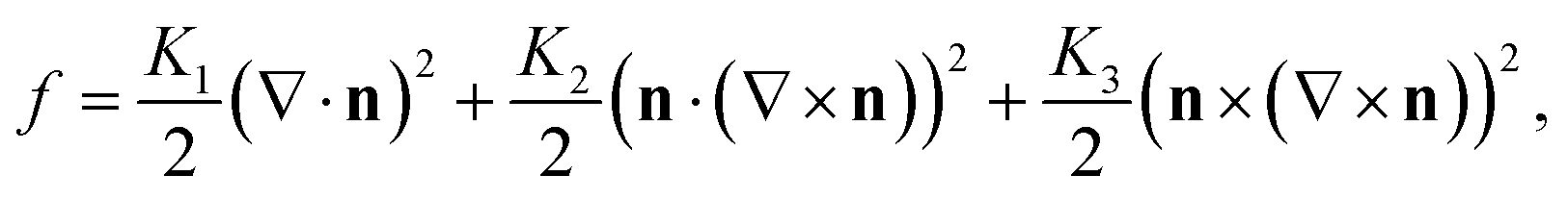 | (1) |
For SmA just before the SmA–SmC transition, on the inner shell surface (Fig. 7(a)),
| m = n ≡ eθ, | (2) |
 | (3) |
 | ||
| Fig. 7 Schematic figure of a SmA shell layer with 3D twist (left) and bend (right), respectively. (a) and (b) At ϕ = 0, the layer normal m twists about er from in- to outside, the rotation in the θϕ-plane reaching an angle β with respect to eθ on the outer surface. (c) At ϕ = ϕA, the layers bend from in- to outside such that m tilts by the angle γ with respect to eθ, in the rθ-plane, away from the outer spherical surface. The equilibrium value of the smectic layer thickness is dA, whereas its projection along eθ is dθ. | ||
With the typical geometrical parameters of our shells (see Section 2), h ≈ 5 μm, R ≈ 120 μm and consequently ε = h/R ≈ 0.05, we obtain a maximum rotation of β ≈ 18°.
Far from a lune boundary, e.g., at ϕ = 0 as defined in Fig. 1(c), the orientation of m||n at the outer surface (r = Ro), at the equator (θ = π/2) is thus (Fig. 7(b)):
| m(Ro,π/2,0) = n(Ro,π/2,0) = cosβeθ ± sinβeϕ. |
At the lune boundary, for example at ϕ = ϕA (see Fig. 1(c)), the twist must go locally to zero to accommodate the undulation from clockwise to anticlockwise twisting, leaving the layer normal m in the rθ-plane. As mentioned above, the layers then bend to avoid layer dilation also here, m locally tilting out of the outer shell boundary plane in the rθ-plane (Fig. 7(c)) at the cost of violating the tangential boundary conditions. Analogous to the analysis of the twist along er with layer rotation in the θϕ-plane within the lunes, we have at the SmA lune boundaries the maximum angle by which m tilts out of the outer surface:
 | (4) |
| m(Ro,π/2,ϕA) = n(Ro,π/2,ϕA) = cosγeθ ± sinγer. |
 | ||
Fig. 8 Schematic figure of a 3D twist and/or bend SmC layer. (a), (b1) When τ < β, at ϕ= 0, the layer normal m twists about er from in- to outside, the rotation in the θϕ-plane starting from an angle τ to β with respect to eθ on the outer surface, and splays in the rθ-plane reaching an angle τ. (a), (b2) When τ > β, at ϕ = 0, the layer normal m splays from in- to outside in the er and cosτeθ + sinτeϕ-plane reaching an angle β. (a), (b3) When τ = β, at ϕ = 0, the layer normal m splays from in- to outside in the er and cosτ(β)eθ + sinτ(β)eϕ-plane reaching an angle τ (β). (c) At ϕ = ϕc, the layers bend from in- to outside such that the layer normal m tilts from the angle τ to δ with respect to eθ, in the rθ-plane, away from the outer spherical surface. The equilibrium value of the SmC layer thickness is dC, whereas the length in a layer at the outer surface r = Ro along m(R,π/2,0) = cosτeθ + sinτeϕ is  . . | ||
In a conventional tangential-aligned smectic between flat substrates, at the SmA–SmC transition n tilts out of its initial orientation into the boundary plane while m remains as it was in SmA.31 In the shell case, however, to maintain the constant number of layers N, i.e., to maintain the constant length in a layer along eθ, πR/N = dA, on the inner shell surface at r = R, n remains as it was in SmA (2),
| n(R,π/2,0) = eθ, | (5) |
| m(R,π/2,0) = cosτeθ ± sinτeϕ. | (6) |
The layer thickness, as measured along m, is dC = dAcosτ.
As defined in eqn (3), the maximum rotation angle β of the SmA layer on the outer shell surface (r = Ro) far from lune boundaries depends on the geometry parameter ε and is independent of temperature. As temperature decreases from TAC and the intrinsic SmC tilt angle τ increases from zero, we go through three distinct regimes: τ < β, τ = β and τ > β. In the three cases, the layer twisting is avoided or reduced, profiting from the freedom of director rotation about the tilt cone and bending of the layers, as mentioned in the introduction. We note that the structures of the layers bending upwards and downwards in the rθ-plane are completely symmetrical about the θϕ-plane, hence we discuss only upward bending. We first consider the initial and final regimes, and end by considering the borderline case.
Case 1: τ < β (Fig. 8(b1)).
Due to the increase of dS from inner to outer surface, the length in a layer along eθ at r = Ro becomes, as usual, dθo = π(R + h)/N = dA(1 + ε) (in red) with ε = h/R. The layer thickness dC (in gray) is constant. To minimise layer twisting, i.e., to maximise the length in a layer along the projection of m on the θϕ-plane, the maximum of which is dA = dC/cosτ (in blue), the SmC tilt cone orientation at the outer shell boundary exactly touches the θϕ-plane at r = Ro. Hence, the out of θϕ-plane angle of m is τ and n rotates around the SmC tilt cone as we move along er from the shell inside to outside, effectively experiencing an in-θϕ-plane rotation by the angle β. The orientations of the director n and layer normal m are
| n(Ro,π/2,0) = cosβeθ ± sinβeϕ, | (7) |
| m(Ro,π/2,0) = cosτ(cosβeθ ± sinβeϕ) − sinτer. | (8) |
The director n twists from the in- to outside reaching a maximum rotation value of β. The layer normal m rotates about er from the inner surface with angle τ to the outer surface with the angle β. The maximum rotation angle, i.e. twisting angle, measured as the angle between the projections of m on the θϕ-plane on the inner and outer surface, respectively, is β–τ, which is less than the corresponding angle in SmA, β in Section 3.2.1. The layer bends in the plane spanned by cosβeθ ± sinβeϕ and er with angle τ.
Case 2: τ > β (Fig. 8(b2)).
With τ > β, the layer twisting about er can be totally avoided by retaining m in the same plane, from inner to outer surface. Since m in the inner surface is cosτeθ ± sinτeϕ, m in the outer surface is in the plane spanned by cosτeθ ± sinτeϕ and er. Again, the outer interface length in a layer along eθ becomes dθo = dA(1 + ε) (in red) and the length in a layer along cosτeθ ± sinτeϕ becomes 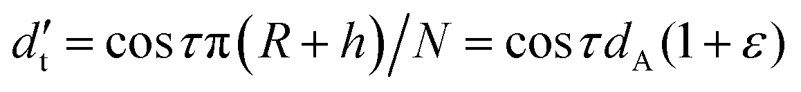 (in green). To retain the layer thickness dC (in gray), the out of θϕ-plane angle of m is
  . Since n is on the θϕ-plane to satisfy the tangential anchoring, and the length in a layer along n is dA (in blue), the angle between n and cosτeθ + sinτeϕ is
 | (9) |
| n(Ro,π/2,0) = cos(τ–κ)eθ ± sin(τ–κ)eϕ, | (10) |
| m(Ro,π/2,0) = cosβ(cosτeθ ± sinτeϕ) − sinβer. | (11) |
The director n twists from the in- to outside reaching a maximum rotation value of τ–κ. From in- to outside, the twisting angle of the layer normal is zero, and the layers bend in the plane spanned by cosτeθ ± sinτeϕ and er with angle β.
Case 3 τ = β (Fig. 8(b3)).
Substituting τ = β into (8) and (11), we obtain the same result:
| n(Ro,π/2,0) = cosτeθ ± sinτeϕ, | (12) |
| m(Ro,π/2,0) = cosτ(cosτeθ ± sinτeϕ) − sinτer. | (13) |
The director n twists from the in- to outside reaching a maximum rotation value of τ (equal to β). From in- to outside, the rotation of the layer normal is zero, and the layers bend in the plane spanned by cosτeθ ± sinτeϕ and er with angle τ.
At ϕ = 0, on the outer surface, the layers bend out of the θϕ-plane as described in eqn (8), (11) and (13). Even if the bend in SmA is concentrated at the lune boundaries, the same bending direction is sensed from the center of one lune (e.g., ϕ = 0) to the center of the adjacent lune (e.g., ϕ = 2ϕA), and then the opposite bending direction prevails until the center of the next lune (e.g., from ϕ = 2ϕA to ϕ = 4ϕA). If we were to continue to assume that the layers bend upwards and downwards alternately, like in SmA shells, this would lead to discontinuities in m, as can be seen from the overlapping sets of layers drawn with opposite bending directions in Fig. 2(c) and as also illustrated in Fig. 9. The problem is identical to that of opposite directions of layer tilt meeting along boundaries between chevrons of opposite sign in surface-stabilized ferroelectric SmC* samples, giving rise to the infamous zigzag defects which deteriorate the performance of electrooptic devices.43 Therefore, once the SmC phase structure is stable, the lune width is doubled compared to that in SmA to ensure the same direction of layer bending, either upwards or downwards.
 | ||
| Fig. 9 Schematic of how lunes could double their width below the SmA–SmC transition. Starting from the twisted lune SmA configuration (a) the layers on the shell inside (black) rotate (b) to match the outside (red), but this leads to a conflict in bend directions (blue arrows along the top of each drawing). Therefore, every second lune boundary must be removed to expel the unfavorable twist in the stable SmC configuration (c). In SmA, the azimuthal angle ϕ is defined zero at the center of the first SmA lune and ϕA at the first SmA lune boundary. In SmC, ϕ is defined zero at the center of the first SmC lune and ϕC at the first SmC lune boundary. The layer normal m is depicted purple at the inner shell boundary and green at the outer shell boundary, while the director n is depicted cyan at the inner and orange at the outer shell boundary. A simple line represents n or m in the plane of the figure, while a shorter line with a perpendicular line at the top (‘nail head’) indicates that n/m tilts out of the image plane, with the nail head being below that plane. | ||
At a SmC lune boundary, for example, ϕ = ϕC, n and m are influenced by the clockwise and counterclockwise rotation from both sides, prevailing since SmA. We assume n and m always lie on the rθ-plane (Fig. 8(c)). On the inner surface, n = eθ, just like in the region far from the lune boundary. To maintain the angle τ between m and n, the out of θϕ-plane angle of m is τ, and we have
| n(R,π/2,ϕC) = eθ, | (14) |
| m(R,π/2,ϕC) = cosτeθ − sinτer. | (15) |
On the outer surface, the length in a layer along eθ is dθo = dA(1 + ε). To keep the layer thickness constant as dC, the out of θϕ-plane angle of m is
 | (16) |
To maintain the angle τ between m and n, the out of θϕ-plane angle of n is δ−τ, and we have
| n(Ro,π/2,ϕC) = cos(δ−τ)eθ − sin(δ−τ)er, | (17) |
| m(Ro,π/2,ϕC) = cosδeθ − sinδer. | (18) |
3.3 Changes during the SmA–SmC transition in a shell
Considering the dynamic process, as temperature decreases from TAC, i.e., the intrinsic SmC tilt angle τ increases from zero, the degree of layer twist about er decreases and the degree of out-of θϕ-plane bending increases until τ reaches β. After τ exceeds β, the layer normal is uniformly rotated in the θϕ-plane, from shell in- to outside, with an increasing angle τ, and the degree of out-of θϕ-plane bending no longer changes. As is seen in Fig. 3(b), we may expect τ = β ≈ 18° at a reduced temperature of about Tr ≈ −19 °C (⇔T ≈ 31 °C).As follows from the above discussions of the three cases, even if m is untwisted, the director field n still exhibits some twist also with τ≥β. In fact, the rotation of n on the surface of the SmC tilt cone amounts to a deformation that combines splay, bend and twist in n. Since this director deformation is mediated via a continuous slow variation of φ, this deformation costs little energy. As a consequence, such a SmC-cone-mediated twist in n is known to form spontaneously, for instance in flat tangentially aligned LC cells with chevron geometry,32 which can be seen as an extreme version of the bent layers that we discuss here.
Finally, we discuss why the secondary modulation disappears in SmC. If the origin of the secondary modulation is the twist in m within the SmA lunes, as suggested by Liang et al.,22 the disappearance is to be expected in SmC of sufficiently large τ, since the twist of the layer normal disappears in favor of bend. Nevertheless, it is somewhat surprising that the secondary modulation seems to disappear almost immediately after the SmA–SmC transition, while τ < β. Possibly, it is still present but difficult to detect due to the significant rearrangement of the lune structure that takes place while cooling through the SmC phase. Another contribution may come from the fact that the value of τ has low impact on the free energy near the second-order SmA–SmC phase transition, giving rise to critical fluctuations and at the heart of the well-known soft mode of a chiral SmA* phase near its transition to SmC*.31 With this freedom to vary τ with little impact on the free energy, the SmC phase at temperatures only slightly below TAC may adopt a value of τ that is greater than its bulk value in order to resolve the frustration arising from the confinement in the shell. Once we heat the shells back to the SmA phase, the twist in m must reappear, even if the lunes retain their SmC-like width, and then the secondary modulation is again needed to compensate for the rotation of m from shell in- to outside.
4 Conclusion and outlook
A SmA–SmC phase transition of liquid crystal shells with tangential boundary conditions for the director n triggers a significant texture change that reflects a smectic layer rearrangement to reduce confinement-induced distortion. Starting from a set of narrow spherical lunes in SmA defined by alternating twist and bend of the layer normal m, in alternating senses, a SmC phase with sufficiently large tilt angle τ adopts a configuration where m only bends, without twist. In the SmC phase the LC can solve the geometrical frustration of layers extending from a small inner boundary to a larger outer one by bending the layers and letting the director rotate around the surface of the SmC tilt cone. Without layer twist, the secondary modulation within lunes that is characteristic of SmA shells disappears after the transition to SmC, which also shows twice as wide lunes since one uniform bending direction is selected.This is only the first presentation of the SmC phase in LC shells with tangential alignment and there are many directions that research in this field can take. In principle, the separation into lunes should not even be required in SmC if τ ≥ β. We postulate that reasonably thin (ensuring values of β in the range considered here) shells of LCs where an SmC phase forms directly from an N phase, typically yielding a high value of τ from the start, would exhibit no lunes. We currently have access to no compounds with such a direct N–SmC transition that also have a phase sequence suitable for microfluidic processing and emulsification with aqueous phases, but hopefully such compounds can be identified, allowing this experiment to be done in the future.
Studying the plethora of different SmC-type phases, including the chiral and thus spontaneously polarized variants, is a particularly exciting avenue. Likewise, adding reactive mesogens can be greatly illuminating since polymerization of the shells allows electron microscopy investigations of the different structures formed with very high resolution.30 If all mesogens are reactive, solid microparticles with exceptional fracture resistance might be produced, benefiting from similar structural reinforcement as in biological high-performance materials, like crustacean exoskeleta44 or shells of nuts,45 templated by the SmA- or SmC-generated modulated director field. Such particles could be used to make, e.g., very light-weight yet durable composite materials.
Data availability
Data for this article, including videos, is available at https://osf.io/38sy5/.Conflicts of interest
There are no conflicts to declare.Acknowledgements
This research was funded by the Luxembourg National Research Fund (FNR), grant references C20/MS/14771094 (ECLIPSE) and 2016/10935404 (doctoral training grant PRIDE MASSENA). For the purpose of open access, the authors have applied a Creative Commons Attribution 4.0 International (CC BY 4.0) license to any Author Accepted Manuscript version arising from this submission. AM is supported by the University of Strathclyde New Professors Fund, the Humboldt Foundation and a Leverhulme Research Project Grant RPG-2021-401. YH is supported by the Sir David Anderson Bequest Award at the University of Strathclyde and a Leverhulme Project Research Grant RPG-2021-401. We thank P. Rudquist for helpful discussions on the optics of twisted SmC structures.Notes and references
- D. R. Nelson, Nano Lett., 2002, 2, 1125–1129 CrossRef CAS.
- H. Eimura, D. S. Miller, X. Wang, N. L. Abbott and T. Kato, Chem. Mater., 2016, 28, 1170–1178 CrossRef CAS.
- L. Shang, Y. Cheng and Y. Zhao, Chem. Rev., 2017, 117, 7964–8040 CrossRef CAS PubMed.
- A. Nikoubashman, D. A. Vega, K. Binder and A. Milchev, Phys. Rev. Lett., 2017, 118, 217803 CrossRef PubMed.
- P. Romano and E. G. Virga, Continuum Mech. Thermodyn., 2000, 12, 363–378 CrossRef.
- S. Samitsu, Y. Takanishi and J. Yamamoto, Nat. Mater., 2010, 9, 816–820 CrossRef CAS PubMed.
- M. R. Khadilkar and A. Nikoubashman, Soft Matter, 2018, 14, 6903–6911 RSC.
- X. Wang, D. S. Miller, E. Bukusoglu, J. J. De Pablo and N. L. Abbott, Nat. Mater., 2016, 15, 106–112 CrossRef CAS PubMed.
- J. Dzubiella, M. Schmidt and H. Löwen, Phys. Rev. E: Stat., Nonlinear, Soft Matter Phys., 2000, 62, 5081 CrossRef CAS PubMed.
- T. Lopez-Leon and A. Fernandez-Nieves, Colloid Polym. Sci., 2011, 289, 345–359 CrossRef CAS.
- M. Urbanski, C. G. Reyes, J. Noh, A. Sharma, Y. Geng, V. S. R. Jampani and J. P. Lagerwall, J. Phys.: Condens. Matter, 2017, 29, 133003 CrossRef PubMed.
- T. K. Fam, A. S. Klymchenko and M. Collot, Materials, 2018, 11, 1768 CrossRef PubMed.
- O. V. Manyuhina and M. J. Bowick, Int. J. Non Linear Mech., 2015, 75, 87–91 CrossRef.
- A. Sharma, R. Kizhakidathazhath and J. Lagerwall, Soft Matter, 2023, 19, 2637–2645 RSC.
- A. Sharma and J. P. Lagerwall, Liq. Cryst., 2018, 45, 2319–2328 CrossRef CAS.
- A. Sharma, D. Gupta, G. Scalia and J. P. F. Lagerwall, Phys. Rev. Res., 2022, 4, 013130 CrossRef CAS.
- A. Fernandez-Nieves, V. Vitelli, A. Utada, D. R. Link, M. Marquez, D. R. Nelson and D. A. Weitz, Phys. Rev. Lett., 2007, 99, 157801 CrossRef CAS PubMed.
- T. Lopez-Leon, V. Koning, K. B. S. Devaiah, V. Vitelli and A. Fernandez-Nieves, Nat. Phys., 2011, 7, 391–394 Search PubMed.
- M. J. Press and A. S. Arrott, Phys. Rev. Lett., 1974, 33, 403–406 CrossRef CAS.
- D. W. Allender and S. Zumer, Liquid Crystal Chemistry, Physics, and Applications, 1989, p. 18 Search PubMed.
- A. Golemme, S. Zumer, D. W. Allender and J. W. Doane, Phys. Rev. Lett., 1988, 61, 26 CrossRef PubMed.
- H. L. Liang, S. Schymura, P. Rudquist and J. Lagerwall, Phys. Rev. Lett., 2011, 106, 247801 CrossRef PubMed.
- T. Lopez-Leon, A. Fernandez-Nieves, M. Nobili and C. Blanc, Phys. Rev. Lett., 2011, 106, 247802 CrossRef PubMed.
- H. L. Liang, R. Zentel, P. Rudquist and J. Lagerwall, Soft Matter, 2012, 8, 5443–5450 RSC.
- T. Lopez-Leon, A. Fernandez-Nieves, M. Nobili and C. Blanc, J. Phys.: Condens. Matter, 2012, 24, 284122 CrossRef PubMed.
- H. L. Liang, J. Noh, R. Zentel, P. Rudquist and J. P. Lagerwall, Philos. Trans. R. Soc., A, 2013, 371, 20120258 CrossRef PubMed.
- J. P. F. Lagerwall and F. Giesselmann, ChemPhysChem, 2006, 7, 20–45 CrossRef CAS PubMed.
- J. Noh, PhD thesis, University of Luxembourg, 2018, https://orbilu.uni.lu/handle/10993/35416 Search PubMed.
- C. Blanc, G. Durey, R. D. Kamien, T. Lopez-Leon, M. O. Lavrentovich and L. Tran, Rev. Mod. Phys., 2023, 95, 015004 CrossRef.
- J. P. F. Lagerwall, Liq. Cryst., 2023, 51, 1296–1310 CrossRef PubMed.
- S. T. Lagerwall, Ferroelectric and antiferroelectric liquid crystals, Wiley-VCH, Weinheim, 1999 Search PubMed.
- J. P. F. Lagerwall, A. Kane, N. A. Clark and D. M. Walba, Phys. Rev. E: Stat., Nonlinear, Soft Matter Phys., 2004, 70, 031703 CrossRef PubMed.
- K. May, K. Harth, T. Trittel and R. Stannarius, EPL, 2012, 100, 16003 CrossRef.
- K. May, K. Harth, T. Trittel and R. Stannarius, ChemPhysChem, 2014, 15, 1508–1518 CrossRef CAS PubMed.
- E. Enz, PhD thesis, Martin-Luther-Universität Halle-Wittenberg, Halle, Germany, 2013 Search PubMed.
- A. S. Utada, E. Lorenceau, D. R. Link, P. D. Kaplan, H. A. Stone and D. A. Weitz, Science, 2005, 308, 537–541 CrossRef CAS PubMed.
- H. Shin, M. Bowick and X. Xing, Phys. Rev. Lett., 2008, 101, 037802 CrossRef PubMed.
- X. Xing, J. Stat. Phys., 2009, 134, 487–536 CrossRef.
- D. Sec, T. Lopez-Leon, M. Nobili, C. Blanc, A. Fernandez-Nieves, M. Ravnik and S. Zumer, Phys. Rev. E: Stat., Nonlinear, Soft Matter Phys., 2012, 86, 020705(R) CrossRef PubMed.
- J. Noh and J. P. Lagerwall, Crystals, 2021, 11, 913 CrossRef CAS.
- J. Noh, B. Henx and J. P. Lagerwall, Adv. Mater., 2016, 28, 10170–10174 CrossRef CAS PubMed.
- F. C. Frank, Crystals That Flow: Classic Papers from the History of Liquid Crystals, 2004, vol. 2, p. 389 Search PubMed.
- N. A. Clark and T. P. Rieker, Phys. Rev. A, 1988, 37, 1053–1056 CrossRef PubMed.
- J. C. Weaver, G. W. Milliron, A. Miserez, K. Evans-Lutterodt, S. Herrera, I. Gallana, W. J. Mershon, B. Swanson, P. Zavattieri, E. DiMasi and D. Kisailus, Science, 2012, 336, 1275–1280 CrossRef CAS PubMed.
- J. Huss, S. Antreich, J. Bachmayr, N. Xiao, M. Eder, J. Konnerth and N. Gierlinger, Adv. Mater., 2020, 32, e2004519 CrossRef PubMed.
Footnotes |
| † Electronic supplementary information (ESI) available. See DOI: https://doi.org/10.1039/d4sm01263a |
| ‡ These authors contributed equally to this work. |
| § In the SmC research literature the tilt angle is typically denoted θ, but here we avoid this to avoid confusion with the polar angle θ required to define locations on the spherical shell. |
| This journal is © The Royal Society of Chemistry 2024 |