 Open Access Article
Creative Commons Attribution 3.0 Unported Licence
Upcycling of low value end-of-life cathode material into next generation cathode materials†
R.
Madge
 *ab,
A.
Jarvis
 ab,
W.
Lima da Silva
 ab,
L. L.
Driscoll
 ab,
P. A.
Anderson
 ab and
P. R.
Slater
 ab
ab
aSchool of Chemistry, University of Birmingham, Birmingham, B15 2TT, UK. E-mail: rxm503@student.bham.ac.uk
bThe Faraday Institution, Harwell Science and Innovation Campus, Didcot, OX11 0RA, UK
First published on 2nd April 2024
Abstract
The increase in the use of electric vehicles (EVs) will ultimately lead to an increase in the number of end-of-life lithium-ion batteries (LIBs) that need to be recycled. A particular challenge concerns how to deal with low value cathodes, such as LiMn2O4 (LMO). To this end, this paper investigates recycling cathode material from an end-of-life Gen 1 Nissan Leaf (2011 model, 40![[thin space (1/6-em)]](https://www.rsc.org/images/entities/char_2009.gif) 000 miles) which contains a mixture of spinel (LMO) and a Ni-rich layered oxide (LO). Citric acid was employed to selectively leach LMO into solution while leaving the remaining LO as a solid. The citric acid also acts as a delamination agent to remove the remaining LO from the Al current collector. The LMO was then recovered from solution and upcycled to form new cathode materials. Ni-doping of the solution allowed the synthesis of the high voltage cathode LiMn1.5Ni0.5O4 (LMNO) which is attracting commercial interest. Disordered rocksalt compounds Li4Mn2O5 and Li2MnO2.25F were also synthesised and gave high specific discharge capacities of 293 and 279 mA h g−1 respectively. This proof of concept work demonstrates a method to upcycle end-of-life cathode material into next generation cathode materials.
000 miles) which contains a mixture of spinel (LMO) and a Ni-rich layered oxide (LO). Citric acid was employed to selectively leach LMO into solution while leaving the remaining LO as a solid. The citric acid also acts as a delamination agent to remove the remaining LO from the Al current collector. The LMO was then recovered from solution and upcycled to form new cathode materials. Ni-doping of the solution allowed the synthesis of the high voltage cathode LiMn1.5Ni0.5O4 (LMNO) which is attracting commercial interest. Disordered rocksalt compounds Li4Mn2O5 and Li2MnO2.25F were also synthesised and gave high specific discharge capacities of 293 and 279 mA h g−1 respectively. This proof of concept work demonstrates a method to upcycle end-of-life cathode material into next generation cathode materials.
Sustainability spotlightRecently, there has been an increase in the use of lithium-ion batteries (LIB). LIB have a finite lifetime and therefore we must develop methods to deal with these batteries once they reach their end of life (EOL). These methods should enable the batteries to be recycled and therefore allow recovery of the elements contained within them. This work looks at recycling the cathode from an EOL LIB. In particular it investigates upcycling the cathode material into next generation cathode materials for future LIB. This work aligns with the UN's Sustainability Development Goals of responsible consumption and production, and climate action. Effective recycling of LIB will allow decreased consumption of raw materials and could reduce processing steps required in subsequent batteries. |
1. Introduction
Governments worldwide are pushing for the electrification of transport to reduce global CO2 emissions and mitigate global warming. For example, the UK government has announced a requirement that all new cars and vans will be required to be fully zero emission at the tailpipe by 2035 and similar strategies are being adopted worldwide.1 This transition requires the development of a strategy to efficiently recycle the large number of spent lithium-ion batteries (LIBs) that reach the end of their service lifetime. Similarly the EU has introduced a requirement for LIBs to contain a minimum level of recycled content (16% Co, 6% Li and 6% Ni) by 2030 with values increasing for subsequent years.2 In the US, the Infrastructure Investment and Jobs Act provides $60 million for research into battery recycling and $15 million for retailers to fund battery recycling programs.3 It is therefore imperative that these spent LIBs are either reused in other applications or recycled to produce materials for such new batteries. Recycling LIBs is crucial as it reduces demands upon the supply chain for critical elements, such as Co and Ni.Currently LIB recycling in the EU is mainly done via pyrometallurgical recovery.4 This involves heating the LIBs to high temperatures to allow the recovery of an alloy of the higher value metals, such as Ni, Co, Cu. This is often followed by hydrometallurgical steps to separate the different metals from this alloy. Pyrometallurgical recovery is widely used as it can deal with the whole battery at once without the need to separate the different battery components. Furthermore, it can be used regardless of battery chemistry and removes the need for a discharging step. However, the pyrometallurgical process is energy intensive and loses much of the materials value within the battery; the synthesis of battery materials is a costly process, and so breaking them down completely into the individual elements loses inherent value. An alternative is direct hydrometallurgical recovery which involves using aqueous solutions to leach the elements into acidic solution. Commonly H2SO4 is used along with H2O2 which acts as a reducing agent. Hydrometallurgical recovery can recover multiple metals and can be performed on a range of different cathode materials. The conventional hydrometallurgical recycling route dissolves all the metals into solution and then separates them using multiple processes. This work investigates the potential to reduce the number of processes required by removing some of these separation steps and therefore reducing recycling costs.
Most of the literature concerning hydrometallurgical recovery reports using an acid, or multiple acids, to leach one type of cathode material (such as LiCoO2 [LCO], LiMn2O4 [LMO], LiNi0.33Mn0.33Co0.33O2 [NMC111]) and have focused on single phase cathode regeneration. The elements in solution can then be used to reform the original material or upcycled to form a more desirable material. Recovered LiFePO4 (LFP) and LMO have been used to synthesise LFP/C and LiMnPO4/C nanocomposites respectively with good cycling performance reported.5,6 Recovered LMO has also been suggested as a potential cathode material for sodium ion batteries.7
Within electric vehicles (EVs), mixed cathode materials are sometimes utilised to combine the advantages of the different materials. For example, LiMn2O4 (LMO) can be combined with LiNi0.8Co0.15Al0.05O2 (NCA) or LiNixMnyCozO2 (NMC) to synergise the thermal stability of the LMO component with the high capacity and long lifetime provided by the NCA/NMC component.8,9 However, this increases the complexity of recycling as there are more components within the cathode that must be considered within recycling processes. Furthermore, future waste streams are likely to contain mixtures of different cathode chemistries through shredding together of batteries from different sources. This is particularly the case for consumer batteries for portable devices, such as mobile phones. Zou et al. proposed a method to recycle mixed cathode materials containing LCO, LMO, NMC111 and LFP and then form NMC111.10 Similar cathode materials have also been used to form NMC532 and NMC622.11 Driscoll et al. recently published a paper where ascorbic acid was used to selectively leach one component from a mixed cathode material.12 NMC532 was then formed from the leaching solution. More recently, there have also been studies which look at upcycling of low Ni-NMCs into high Ni-NMCs.13–16 While these methods appear promising, they represent the manufacture of current or older generation cathode materials from end-of-life materials. In the future there must be a focus on upcycling to form next generation cathode materials to ensure that recycling is adapting to the evolving battery landscape.
LiMn1.5Ni0.5O4 (LMNO) is one example of a new material that is gaining interest for next generation LIBs due to its high operating voltage (∼4.7 V).17 Its higher operating voltage allows it to be used alongside high voltage anodes, such as Nb oxide based anodes to deliver higher voltage high power cells.18,19 However, this high operating voltage can introduce problems when using conventional electrolytes as they are not typically stable at higher voltages and so electrolyte additives are required.20 LMNO can be synthesised by a variety of methods such as solid state, co-precipitation, sol–gel, and hydrothermal.21 The different synthesis methods and reaction conditions have an influence upon the structure and electrochemical performance of LMNO. LMNO can form an ordered (P4332) or disordered (Fd![[3 with combining macron]](https://www.rsc.org/images/entities/char_0033_0304.gif) m) structure depending on the degree of ordering between Ni2+ and Mn4+ in the structure. Ordered LMNO has a flat voltage profile with a voltage plateau at ∼4.7 V due to Ni redox activity. In contrast, disordered LMNO contains a small amount of Mn3+ which results in an additional voltage plateau at 4 V due to Mn3+ redox.
m) structure depending on the degree of ordering between Ni2+ and Mn4+ in the structure. Ordered LMNO has a flat voltage profile with a voltage plateau at ∼4.7 V due to Ni redox activity. In contrast, disordered LMNO contains a small amount of Mn3+ which results in an additional voltage plateau at 4 V due to Mn3+ redox.
Other newer electrodes attracting interest are materials with a disordered rocksalt structure, which have been investigated as high-capacity cathode materials. Freire et al. first reported Li4Mn2O5 which has high initial discharge capacity of 355 mA h g−1 however, the capacity dropped to 250 mA h g−1 after 8 cycles.22 These rocksalt materials undergo high levels of O redox which can result in O loss and a detrimental impact upon the long term cycling performance.23–26 One potential solution is to partially substitute some of the O2− for F− to form oxyfluoride materials which rely less heavily upon O redox.27,28 House et al. have reported Li1.9Mn0.95O2.05F0.95 which has a high capacity of 280 mA h g−1 and undergoes negligible O loss during cycling.29 Similarly Lun et al. have reported Li1.25Mn0.75O1.3333F0.6667 which has a discharge capacity of 256 mA h g−1 and undergoes less than 15% capacity fade over 30 cycles.30 It is therefore of interest to see if materials from spent LIBs can be upcycled to such disordered rocksalt materials.
With a view to ensuring that LIB recycling aligns with the advances in electrode chemistry, this work examines upcycling of a low value component of a 1st generation EV battery into higher value new cathode materials. The work examines recovering material from a LIB which contains a mixture of LMO and a Ni-rich layered oxide (LO). In contrast to many previous studies which focus on “model” systems, this work uses material that is recovered from an end-of-life EV (Gen 1 Nissan Leaf, 2011 model, 40![[thin space (1/6-em)]](https://www.rsc.org/images/entities/char_2009.gif) 000 miles). Citric acid is employed as a dual reagent to selectively leach LMO into solution whilst also delaminating the remaining LO from the Al current collector. As LMO is low value and not widely employed in new EV batteries, this recovered LMO is then upcycled to synthesise new cathode materials.
000 miles). Citric acid is employed as a dual reagent to selectively leach LMO into solution whilst also delaminating the remaining LO from the Al current collector. As LMO is low value and not widely employed in new EV batteries, this recovered LMO is then upcycled to synthesise new cathode materials.
2. Experimental
An end-of-life LIB (Gen 1 Nissan Leaf, 2011 model, 40![[thin space (1/6-em)]](https://www.rsc.org/images/entities/char_2009.gif) 000 miles) was examined in this study. The cell was safely removed from the module and discharged to 2.7 V. The cell was then manually disassembled using the method reported by Marshall et al. to obtain the cathode sheets.31 The cathode sheets were then washed in diethyl carbonate (Sigma, 99%) before being dried in a fume hood.
000 miles) was examined in this study. The cell was safely removed from the module and discharged to 2.7 V. The cell was then manually disassembled using the method reported by Marshall et al. to obtain the cathode sheets.31 The cathode sheets were then washed in diethyl carbonate (Sigma, 99%) before being dried in a fume hood.
For the leaching procedure, the cathode sheets (20 by 22 cm) were cut into small pieces (approximately 1 by 1 cm). 0.3 g of the cathode pieces were added to 10 mL of 1 M citric acid (Sigma, 99.5%) at 50 °C to selectively leach the LMO into solution. At the end of the stated leaching time (5–20 minutes) the solution was filtered to separate the remaining LO cathode from the citric acid solution. A small sample of the leached solution was used for Inductively Coupled Plasma Optical Emission spectroscopy (ICP-OES) analysis. The remaining solid was put into an oven at 80 °C to dry. The amounts of metals leached into solution were analysed using an Agilent 5110 ICP-OES. Samples were taken from the leaching solution at set times along with matching samples of the remaining solid for complementary analysis. The remaining solid was dissolved in a mixed solution of hydrochloric acid![[thin space (1/6-em)]](https://www.rsc.org/images/entities/char_2009.gif) :
:![[thin space (1/6-em)]](https://www.rsc.org/images/entities/char_2009.gif) nitric acid (3
nitric acid (3![[thin space (1/6-em)]](https://www.rsc.org/images/entities/char_2009.gif) :
:![[thin space (1/6-em)]](https://www.rsc.org/images/entities/char_2009.gif) 1) before ICP-OES analysis.
1) before ICP-OES analysis.
Two approaches were taken to prepare spinel materials using the leached solution: recovery of the LMO or synthesis of LMNO. For recovery of the LMO, the solution was dried on a hotplate before being put into an oven at 200 °C for 4 hours. The remaining residue was ground by hand in a pestle and mortar and placed into an alumina crucible covered by a lid. This crucible was then put into a furnace at 700 °C for 6 hours.
For the synthesis of LMNO, stoichiometric amounts of Li(NO3) and Ni(NO3)2·6H2O were added into the leached solution containing LMO. The small amount of Ni (determined from ICP analysis) within the leaching solution was taken into account when determining the amount of Ni(NO3)2·6H2O to add. The solution was stirred and heated to 60 °C for 30 minutes. The solution was then dried on a hotplate before being put into an oven at 350 °C for 8 hours to allow the nitrates to decompose.32 The remaining residue was then ground by hand in a pestle and mortar and placed into an alumina crucible. This crucible was then put into a furnace at 700 °C for 12 hours under an O2 atmosphere.
For the upcycling to disordered rocksalt type Li4Mn2O5 and Li2MnO2.25F, stoichiometric quantities of recovered LiMn2O4, Li2O and MnO or LiF (eqn (1) and (2)) were weighed out using an analytical balance (±0.1 mg) in an Ar-filled glovebox. These reagents were then ground together using a Pulverisette 7 planetary ball-mill with 5 mm silicon nitride milling balls and a 45 mL silicon nitride pot at 900 rpm for 8 h. The total milling time was broken up into 10 minutes intervals followed by a 5 minutes rest period to ensure that there was no excessive heating of the milling pots.
| 2LiMn2O4 + 5Li2O + 2MnO → 3Li4Mn2O5 | (1) |
| 0.5LiMn2O4 + 0.25Li2O + LiF → Li2MnO2.25F | (2) |
XRD data were collected using a Bruker D2 phaser with a Co X-ray Kα source (λ = 1.79 Å) and a Bruker D8 diffractometer with a Cu Kα X-ray source (λ = 1.54 Å). Measurements were conducted in the range of 10–90° with a step size of ∼0.02°. Rietveld and Pawley refinements were performed using the GSAS-II and TOPAS version 6 programs.33–35 Scanning electron microscopy (SEM) images were taken using a HITACHI TM4000plus SEM with an AztecOne EDX analyser.
To measure the electrochemical properties of LMO and LMNO, electrodes were prepared by mixing 80 wt% active material with 10 wt% carbon black and 10 wt% PVDF. These materials were added to NMP and mixed using a THINKY ARE-250 planetary mixer to form a slurry before coating onto Al foil. Individual circular electrodes were then cut out of the electrode coatings. 2032 coin cells were manufactured by assembling a bottom cap, an electrode, a separator soaked in electrolyte (1 M LiPF6 in a solution of 50![[thin space (1/6-em)]](https://www.rsc.org/images/entities/char_2009.gif) :
:![[thin space (1/6-em)]](https://www.rsc.org/images/entities/char_2009.gif) 50 ethylene carbonate
50 ethylene carbonate![[thin space (1/6-em)]](https://www.rsc.org/images/entities/char_2009.gif) :
:![[thin space (1/6-em)]](https://www.rsc.org/images/entities/char_2009.gif) dimethyl carbonate), a metallic Li counter electrode, a spacer, a spring and a top cap with a gasket. As the disordered rocksalts are more air sensitive, Swagelok cells were used for electrochemical testing. 70 wt% active material (Li4Mn2O5 or Li2MnO2.25F) was mixed with 30 wt% carbon black using a Pulverisette 7 planetary ball-mill at 450 rpm for 2 h. Swagelok cells were then assembled using a metallic Li counter electrode, a separator soaked in electrolyte (1 M LiPF6 in a solution of 50
dimethyl carbonate), a metallic Li counter electrode, a spacer, a spring and a top cap with a gasket. As the disordered rocksalts are more air sensitive, Swagelok cells were used for electrochemical testing. 70 wt% active material (Li4Mn2O5 or Li2MnO2.25F) was mixed with 30 wt% carbon black using a Pulverisette 7 planetary ball-mill at 450 rpm for 2 h. Swagelok cells were then assembled using a metallic Li counter electrode, a separator soaked in electrolyte (1 M LiPF6 in a solution of 50![[thin space (1/6-em)]](https://www.rsc.org/images/entities/char_2009.gif) :
:![[thin space (1/6-em)]](https://www.rsc.org/images/entities/char_2009.gif) 50 ethylene carbonate
50 ethylene carbonate![[thin space (1/6-em)]](https://www.rsc.org/images/entities/char_2009.gif) :
:![[thin space (1/6-em)]](https://www.rsc.org/images/entities/char_2009.gif) dimethyl carbonate) and <10 mg active material. Electrochemical testing was then performed using a Biologic BCS-805 battery cycler.
dimethyl carbonate) and <10 mg active material. Electrochemical testing was then performed using a Biologic BCS-805 battery cycler.
3. Results and discussion
3.1. End-of-life cathode analysis
The XRD pattern of the end-of-life (EOL) cathode shows that it contains a mixture of LMO (Fd![[3 with combining macron]](https://www.rsc.org/images/entities/char_0033_0304.gif) m space group) and a layered oxide (LO; R
m space group) and a layered oxide (LO; R![[3 with combining macron]](https://www.rsc.org/images/entities/char_0033_0304.gif) m space group Fig. 1). Previously the LO phase has been reported to be a Co and Al doped LiNiO2 (NCA) and shown to have a composition of approximately LiNi0.85Co0.1Al0.05O2.31 The EOL cathode also contains a graphitic phase, which could either be due to migration from the anode or due to conductive carbon additives. Rietveld refinement analysis shows that LMO accounts for most of the cathode (61.9 wt%) while the LO accounts for considerably less (18.3 wt%) (Table 1 and Fig. S1†). The wt% is only applicable to crystalline phases and does not include the amorphous carbon/binder added during coating. Both the LMO and LO phases have lattice parameters similar to those reported in the literature (JCPDS cards No. 35-0782 and 87-1562 respectively).36–38 The wt% of the graphitic phase is high (19.8 wt%) and may have been in the original cathode or be due to migration from the anode or due to contamination during disassembly.
m space group Fig. 1). Previously the LO phase has been reported to be a Co and Al doped LiNiO2 (NCA) and shown to have a composition of approximately LiNi0.85Co0.1Al0.05O2.31 The EOL cathode also contains a graphitic phase, which could either be due to migration from the anode or due to conductive carbon additives. Rietveld refinement analysis shows that LMO accounts for most of the cathode (61.9 wt%) while the LO accounts for considerably less (18.3 wt%) (Table 1 and Fig. S1†). The wt% is only applicable to crystalline phases and does not include the amorphous carbon/binder added during coating. Both the LMO and LO phases have lattice parameters similar to those reported in the literature (JCPDS cards No. 35-0782 and 87-1562 respectively).36–38 The wt% of the graphitic phase is high (19.8 wt%) and may have been in the original cathode or be due to migration from the anode or due to contamination during disassembly.
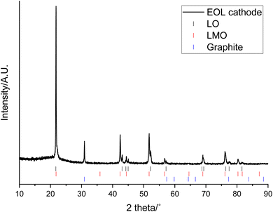 | ||
| Fig. 1 XRD pattern of end-of-life cathode prior to leaching (Co Kα). Tick marks correspond to LO (black), LMO (red) and graphite (blue). | ||
| Phase | a/Å | c/Å | Cell volume/Å3 | wt/% |
|---|---|---|---|---|
| LMO | 8.2083(4) | — | 101.00(2) | 61.9(1) |
| LO | 2.8594(5) | 14.263(1) | 553.04(7) | 18.3(5) |
| Graphite | 2.1512(1) | 6.7217(5) | 26.93(2) | 19.8(1) |
SEM images of the cathode show larger particles consisting of agglomerations of smaller particles, which may be due to larger particles cracking during cycling (Fig. 2). EDX images show that high levels of Mn are present over the majority of surface apart from some regions where there is lower Mn and higher Ni levels. The regions of high Mn content correspond to areas that are rich in the LMO phase while regions of high Ni content correspond to areas that are rich in the LO phase.
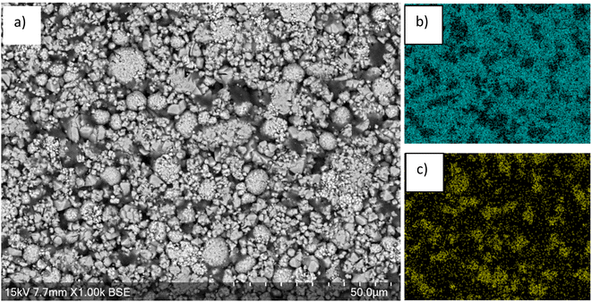 | ||
| Fig. 2 (a) SEM image of end-of-life cathode prior to leaching. EDX images shown in (b) Mn and (c) Ni. | ||
3.2. Cathode after leaching
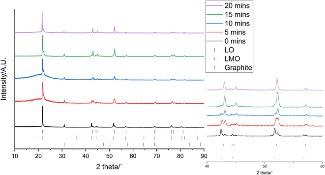
0.3 g of the cathode was placed in 10 mL of 1 M citric acid at 50 °C. In addition to leaching of one component, this also led to delamination of the active material from the Al current collector showing that the citric acid can have a dual effect of selective leaching and delamination. Samples of the cathode and leaching solution were taken at 5, 10, 15 and 20 minutes to investigate the leaching process. XRD patterns of cathode at these times are given in Fig. 3. As the leaching time is increased, the peaks corresponding to LMO decrease in intensity showing that there is increased LMO leaching with time. The XRD data show that the LMO phase is completely leached from the cathode after 20 minutes of leaching. This is indicated by the peaks at 42.4°, 51.8° and 56.8° no longer being present. The LO phase remains intact throughout the leaching duration showing that it is not leached into solution. The XRD patterns also show a shoulder on the peak at 21°. While extensive cycling of LO can lead to a transformation from a layered to a rocksalt structure, this extra peak does not match to a rocksalt phase.39 Instead this shoulder can be attributed to the presence of an additional LO phase being present. This additional LO phase has cell parameters, a = 2.8829(1) Å and c = 13.986(3) Å. The c value is significantly lower than the original LO phase suggesting that it may be a Li-deficient LO.40 This suggests that cell degradation due to extensive cycling has resulted in formation of a Li-deficient LO phase. Alternatively, there may have been a loss of Li during formation of the anode SEI or Li loss during the leaching process. Rietveld refinement analysis using the XRD data shows a decrease in the wt% of the LMO phase which is accompanied by an increase in the wt% of the LO phase with leaching time highlighting the selective nature of the leaching process (Fig. 4). The leaching process does not appear to have any significant impact upon the lattice parameters of either phase (Table S1 and Fig. S2†). The wt% of graphite is constant through-out the leaching process suggesting that some of the graphite must be leached from the cathode during the leaching process.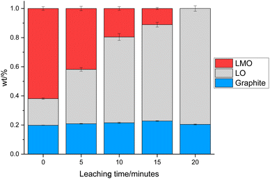 | ||
| Fig. 4 wt% of LMO (red), LO (grey) and graphite (blue) in the end-of-life cathode at different leaching times from XRD analysis. | ||
SEM images of the cathode after 20 minutes of leaching show voids across the surface (Fig. 5), consistent with areas where the LMO particles have been leached from the cathode surface. EDX images show that there is also a lower Mn content across the entire surface. In contrast, there is a higher Ni content across the surface with areas of higher Ni content corresponding to areas where large particle agglomerations remain in the SEM image. The morphology of these larger particles appears to have been retained. This provides further evidence to support the conclusion that the LO phase remains during the leaching process. EDX analysis of the areas that are high in Ni suggests that the LO has a TM molar ratio (Ni![[thin space (1/6-em)]](https://www.rsc.org/images/entities/char_2009.gif) :
:![[thin space (1/6-em)]](https://www.rsc.org/images/entities/char_2009.gif) Mn
Mn![[thin space (1/6-em)]](https://www.rsc.org/images/entities/char_2009.gif) :
:![[thin space (1/6-em)]](https://www.rsc.org/images/entities/char_2009.gif) Co
Co![[thin space (1/6-em)]](https://www.rsc.org/images/entities/char_2009.gif) :
:![[thin space (1/6-em)]](https://www.rsc.org/images/entities/char_2009.gif) Al) of 0.77
Al) of 0.77![[thin space (1/6-em)]](https://www.rsc.org/images/entities/char_2009.gif) :
:![[thin space (1/6-em)]](https://www.rsc.org/images/entities/char_2009.gif) 0.02
0.02![[thin space (1/6-em)]](https://www.rsc.org/images/entities/char_2009.gif) :
:![[thin space (1/6-em)]](https://www.rsc.org/images/entities/char_2009.gif) 0.15
0.15![[thin space (1/6-em)]](https://www.rsc.org/images/entities/char_2009.gif) :
:![[thin space (1/6-em)]](https://www.rsc.org/images/entities/char_2009.gif) 0.05. This ratio matches well to that of NCA other than the presence of a small amount of Mn. This could be due to incomplete leaching of the LMO phase, Mn-doping into the NCA structure or reaction between the two electrode phases during manufacture of the blended cathode.
0.05. This ratio matches well to that of NCA other than the presence of a small amount of Mn. This could be due to incomplete leaching of the LMO phase, Mn-doping into the NCA structure or reaction between the two electrode phases during manufacture of the blended cathode.
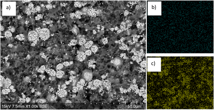 | ||
| Fig. 5 (a) SEM image of end-of-life cathode after 20 min leaching showing removal of the LMO phase. EDX images shown in (b) Mn and (c) Ni. | ||
ICP-OES analysis has been used to calculate the percentage of each element that is present in solution compared to the total that is present in both the solution and cathode (Table 2). It shows that after 20 minutes, 99.9% of the Mn has been leached into solution along with 80.9% of the Li. This presumably corresponds to leaching the Mn and Li that constitute the LMO component of the cathode. In contrast, <10% of the Ni and Al and around 30% of the Co is leached into solution. While this may appear to be a significant amount of Ni/Al/Co leaching, the concentration values (Table S2†) show that the amounts of these metals in solution are considerably smaller compared to the amount of Mn present. Therefore, the ICP-OES results support the conclusion that it is mainly the LMO component that is leached into solution. Furthermore, the percentage of Al in solution is low suggesting that the leaching process does not result in significant loss of Al from the current collector.
| Leaching time/mins | Percentage of element in solution/% | ||||
|---|---|---|---|---|---|
| Li | Mn | Ni | Co | Al | |
| 5 | 42.09 | 43.60 | 1.90 | 12.22 | 2.33 |
| 10 | 63.51 | 76.73 | 2.73 | 21.24 | 3.47 |
| 15 | 76.04 | 98.67 | 3.72 | 24.47 | 4.13 |
| 20 | 80.85 | 99.94 | 7.91 | 30.83 | 5.89 |
ICP-OES analysis of the remaining cathode solid at 20 minutes suggests that it has a TM molar ratio (Ni![[thin space (1/6-em)]](https://www.rsc.org/images/entities/char_2009.gif) :
:![[thin space (1/6-em)]](https://www.rsc.org/images/entities/char_2009.gif) Mn
Mn![[thin space (1/6-em)]](https://www.rsc.org/images/entities/char_2009.gif) :
:![[thin space (1/6-em)]](https://www.rsc.org/images/entities/char_2009.gif) Co
Co![[thin space (1/6-em)]](https://www.rsc.org/images/entities/char_2009.gif) :
:![[thin space (1/6-em)]](https://www.rsc.org/images/entities/char_2009.gif) Al) of 0.78
Al) of 0.78![[thin space (1/6-em)]](https://www.rsc.org/images/entities/char_2009.gif) :
:![[thin space (1/6-em)]](https://www.rsc.org/images/entities/char_2009.gif) 0.03
0.03![[thin space (1/6-em)]](https://www.rsc.org/images/entities/char_2009.gif) :
:![[thin space (1/6-em)]](https://www.rsc.org/images/entities/char_2009.gif) 0.14
0.14![[thin space (1/6-em)]](https://www.rsc.org/images/entities/char_2009.gif) :
:![[thin space (1/6-em)]](https://www.rsc.org/images/entities/char_2009.gif) 0.04 with a TM
0.04 with a TM![[thin space (1/6-em)]](https://www.rsc.org/images/entities/char_2009.gif) :
:![[thin space (1/6-em)]](https://www.rsc.org/images/entities/char_2009.gif) Li molar ratio of 1
Li molar ratio of 1![[thin space (1/6-em)]](https://www.rsc.org/images/entities/char_2009.gif) :
:![[thin space (1/6-em)]](https://www.rsc.org/images/entities/char_2009.gif) 0.40. This matches relatively well to the ratios calculated via EDX analysis. The results, however, do suggest that the remaining cathode may be Li-deficient, matching to the presence of a delithiated LO phase seen in the XRD patterns. ICP-OES analysis of the solution at 20 minutes suggests that it has TM molar ratio (Ni
0.40. This matches relatively well to the ratios calculated via EDX analysis. The results, however, do suggest that the remaining cathode may be Li-deficient, matching to the presence of a delithiated LO phase seen in the XRD patterns. ICP-OES analysis of the solution at 20 minutes suggests that it has TM molar ratio (Ni![[thin space (1/6-em)]](https://www.rsc.org/images/entities/char_2009.gif) :
:![[thin space (1/6-em)]](https://www.rsc.org/images/entities/char_2009.gif) Mn
Mn![[thin space (1/6-em)]](https://www.rsc.org/images/entities/char_2009.gif) :
:![[thin space (1/6-em)]](https://www.rsc.org/images/entities/char_2009.gif) Co
Co![[thin space (1/6-em)]](https://www.rsc.org/images/entities/char_2009.gif) :
:![[thin space (1/6-em)]](https://www.rsc.org/images/entities/char_2009.gif) Al) of 0.02
Al) of 0.02![[thin space (1/6-em)]](https://www.rsc.org/images/entities/char_2009.gif) :
:![[thin space (1/6-em)]](https://www.rsc.org/images/entities/char_2009.gif) 0.93
0.93![[thin space (1/6-em)]](https://www.rsc.org/images/entities/char_2009.gif) :
:![[thin space (1/6-em)]](https://www.rsc.org/images/entities/char_2009.gif) 0.02
0.02![[thin space (1/6-em)]](https://www.rsc.org/images/entities/char_2009.gif) :
:![[thin space (1/6-em)]](https://www.rsc.org/images/entities/char_2009.gif) 0.03 with TM
0.03 with TM![[thin space (1/6-em)]](https://www.rsc.org/images/entities/char_2009.gif) :
:![[thin space (1/6-em)]](https://www.rsc.org/images/entities/char_2009.gif) Li molar ratio of 1
Li molar ratio of 1![[thin space (1/6-em)]](https://www.rsc.org/images/entities/char_2009.gif) :
:![[thin space (1/6-em)]](https://www.rsc.org/images/entities/char_2009.gif) 0.52. Pristine LMO has a TM
0.52. Pristine LMO has a TM![[thin space (1/6-em)]](https://www.rsc.org/images/entities/char_2009.gif) :
:![[thin space (1/6-em)]](https://www.rsc.org/images/entities/char_2009.gif) Li molar ratio of 1
Li molar ratio of 1![[thin space (1/6-em)]](https://www.rsc.org/images/entities/char_2009.gif) :
:![[thin space (1/6-em)]](https://www.rsc.org/images/entities/char_2009.gif) 0.50. This suggests that from this solution, the LMO could be reformed from the solution with only a small amount of Ni/Co/Al contamination. The remaining cathode material (the LO phase) can be recycled using a hydrothermal method (to decompose the PVDF binder) and then heat treatment with LiOH at elevated temperature as reported previously by this group.12
0.50. This suggests that from this solution, the LMO could be reformed from the solution with only a small amount of Ni/Co/Al contamination. The remaining cathode material (the LO phase) can be recycled using a hydrothermal method (to decompose the PVDF binder) and then heat treatment with LiOH at elevated temperature as reported previously by this group.12
3.3. Recovery of LMO phase
The LMO in solution can then be reformed from the acidic solution via heat treatments. The recovered LMO forms the desired spinel phase (Fig. 6a, space group Fd![[3 with combining macron]](https://www.rsc.org/images/entities/char_0033_0304.gif) m) without the presence of any impurity phases. It has a lattice parameter of 8.2019(5) Å which is similar to the literature and suggests that there is no significant Li/Mn deficiency within the structure.37Fig. 6b shows the cycling performance of the recovered LMO (dQ/dV plot in Fig. S3†). The voltage profile looks as expected however it displays a low specific discharge capacity of 89 mA h g−1. This capacity is lower than commonly reported in the literature for LMO (Fig. S4,† 120 mA h g−1),41 which may be due to the presence of small amounts of additional metals noted above. Given this fact, and the fact that LMO is no longer commercially used, we therefore investigated upcycling into next generation cathodes.
m) without the presence of any impurity phases. It has a lattice parameter of 8.2019(5) Å which is similar to the literature and suggests that there is no significant Li/Mn deficiency within the structure.37Fig. 6b shows the cycling performance of the recovered LMO (dQ/dV plot in Fig. S3†). The voltage profile looks as expected however it displays a low specific discharge capacity of 89 mA h g−1. This capacity is lower than commonly reported in the literature for LMO (Fig. S4,† 120 mA h g−1),41 which may be due to the presence of small amounts of additional metals noted above. Given this fact, and the fact that LMO is no longer commercially used, we therefore investigated upcycling into next generation cathodes.
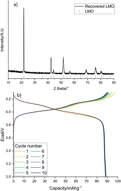 | ||
| Fig. 6 (a) XRD pattern of recovered LMO (Co Kα) with tick marks correspond to LMO and (b) galvanostatic charge–discharge profile of recovered LMO when cycled at 10 m Ag−1 between 3–4.3 V. | ||
3.4. Upcycling the LMO phase to form LiMn1.5Ni0.5O4 (LMNO) cathodes
The recovered LMO can then be used as a reagent to form other, higher performing, Mn containing cathode materials. This provides a method for the recovered LMO to be utilised in an upcycling application. In this example, the solution containing Li and Mn is instead used as a starting material in the synthesis of LMNO rather than recovering LMO. LMNO is of interest as it has a higher operating voltage than LMO and therefore increases the cell energy. It has also been suggested as a cathode to increase the voltage of higher power batteries.18,19 XRD patterns show that the desired spinel phase (space group Fd![[3 with combining macron]](https://www.rsc.org/images/entities/char_0033_0304.gif) m) has formed (Fig. 7). There are also peaks at 43.8, 51.0 and 75.1° which are due to a small amount of LixNi1−xO (6.0 wt%). LixNi1−xO is a common impurity for LMNO and it is usually formed when the synthesis is performed at higher temperatures, as this results in a decrease in the Ni solubility within the spinel structure.17 Different synthesis conditions, such as synthesis temperatures, ramping rates and synthesis atmospheres, were investigated however, LixNi1−xO was present in every upcycled LMNO sample. The LMNO has a lattice parameter of 8.1587(3) Å which is slightly smaller than literature values (8.16–8.18 Å)42 and could be due to the presence of small amounts of additional metals in the recovered LMNO.43,44 LMNO was also synthesised from LMO recovered from a Quality Control Rejected (QCR) cell, which had consequently not undergone extended cycling within an EV. In this case, no LixNi1−xO impurity was seen (Fig. S5†) and so the impurity appears to be related to the degradation that has occurred within the EOL cell. Specifically, the leaching solution for the EOL cell contained 10 times more Co than the leaching solution for the QC cell and therefore some Co incorporation into the spinel could be limiting the Ni solid solution range and so encouraging formation of the impurity phase.
m) has formed (Fig. 7). There are also peaks at 43.8, 51.0 and 75.1° which are due to a small amount of LixNi1−xO (6.0 wt%). LixNi1−xO is a common impurity for LMNO and it is usually formed when the synthesis is performed at higher temperatures, as this results in a decrease in the Ni solubility within the spinel structure.17 Different synthesis conditions, such as synthesis temperatures, ramping rates and synthesis atmospheres, were investigated however, LixNi1−xO was present in every upcycled LMNO sample. The LMNO has a lattice parameter of 8.1587(3) Å which is slightly smaller than literature values (8.16–8.18 Å)42 and could be due to the presence of small amounts of additional metals in the recovered LMNO.43,44 LMNO was also synthesised from LMO recovered from a Quality Control Rejected (QCR) cell, which had consequently not undergone extended cycling within an EV. In this case, no LixNi1−xO impurity was seen (Fig. S5†) and so the impurity appears to be related to the degradation that has occurred within the EOL cell. Specifically, the leaching solution for the EOL cell contained 10 times more Co than the leaching solution for the QC cell and therefore some Co incorporation into the spinel could be limiting the Ni solid solution range and so encouraging formation of the impurity phase.
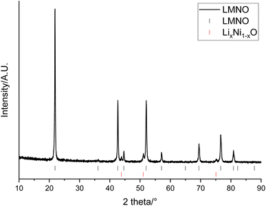 | ||
| Fig. 7 XRD pattern of LiMn1.5Ni0.5O4 made from recovered LMO (Co Kα). Tick marks correspond to LMNO (black) and LixNi1−xO (red). | ||
Electrochemical testing of LMNO shows that it gives an average first cycle specific discharge capacity of 119 mA h g−1 (Fig. 8, capacity retention is 96.8% after 10 cycles, dQ/dV plot in Fig. S6†). This is higher than the recovered LMO (Fig. 6b) and comparable to pristine LMNO (Fig. S7†) and is maintained over subsequent cycles (Fig. S8†). There are voltage plateaus at ∼4 V due to Mn3+/4+ redox and at ∼4.7 V due to Ni2+/4+ redox. The presence of some Mn3+ is common for LMNO and is often observed when LixNi1−xO impurities are present and the disordered structure is formed. Although Mn3+ lowers the overall voltage it has been found to improve the cycling performance of LMNO as it increases the electrical conductivity.42 A standard electrolyte was used in the cells therefore improvements could be made to the capacity retention by moving to a more suitable electrolyte with high voltage stability. This work nevertheless indicates that recovered LMO can be used as a reagent to synthesise LMNO which has a comparable electrochemical performance to pristine LMNO. This therefore provides a route for upcycling LMO into a commercially relevant cathode material.
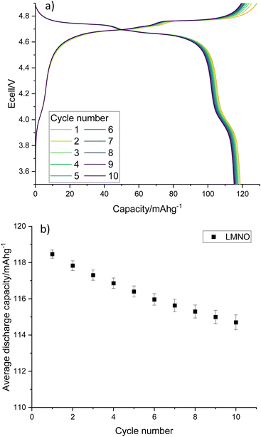 | ||
| Fig. 8 (a) Galvanostatic charge–discharge profile and (b) average gravimetric discharge capacity against cycle number for LMNO. Cells were cycled at 10 m Ag−1 between 3.5–4.9 V. | ||
3.5. Upcycling the LMO phase to form cation disordered rocksalt cathodes
An alternative option is to upcycle the recovered LMO into cation disordered rocksalts compounds. Recovered LMO has therefore been used as a reagent to form Li4Mn2O5 and Li2MnO2.25F (these compositions were selected due to constraints imposed when using LMO as a reagent, see eqn (1) and (2)). These both have a cation disordered rocksalt structure (Fm![[3 with combining macron]](https://www.rsc.org/images/entities/char_0033_0304.gif) m space group) and have been shown to provide a high capacity when used as cathode materials. XRD patterns of the materials show that the disordered rocksalt structure has been successfully formed (Fig. 9 and S9†). The broad peaks are a feature of DRS phases, which are synthesised using mechanochemical methods. Such a ball milling synthesis approach is required for the synthesis of these Li–Mn–O(F) DRS phases, and our recent mechanistic studies of ball milling synthesis have suggested that the ball milling creates local heating and pressure effects to facilitate the synthesis. In particular the local pressure effects are very important, and so consequently these phases cannot be synthesised by standard solid state synthesis.45 This is the first example of the use of recycled EV material for the synthesis of these phases. Table 3 shows the lattice parameters of the materials which are similar to literature values.22,29 The Mn oxidation state is 3+ for Li4Mn2O5 and 3.5+ for Li2MnO2.25F therefore the average Mn ionic radius is smaller in Li2MnO2.25F leading to a consequently smaller lattice parameter. The (111) peak is not present for Li2MnO2.25F, this could be due to F-doping changing the long-range order in the structure.46,47
m space group) and have been shown to provide a high capacity when used as cathode materials. XRD patterns of the materials show that the disordered rocksalt structure has been successfully formed (Fig. 9 and S9†). The broad peaks are a feature of DRS phases, which are synthesised using mechanochemical methods. Such a ball milling synthesis approach is required for the synthesis of these Li–Mn–O(F) DRS phases, and our recent mechanistic studies of ball milling synthesis have suggested that the ball milling creates local heating and pressure effects to facilitate the synthesis. In particular the local pressure effects are very important, and so consequently these phases cannot be synthesised by standard solid state synthesis.45 This is the first example of the use of recycled EV material for the synthesis of these phases. Table 3 shows the lattice parameters of the materials which are similar to literature values.22,29 The Mn oxidation state is 3+ for Li4Mn2O5 and 3.5+ for Li2MnO2.25F therefore the average Mn ionic radius is smaller in Li2MnO2.25F leading to a consequently smaller lattice parameter. The (111) peak is not present for Li2MnO2.25F, this could be due to F-doping changing the long-range order in the structure.46,47
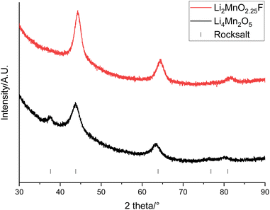 | ||
| Fig. 9 XRD patterns of Li4Mn2O5 (black) and Li2MnO2.25F (red) made from recovered LMO (Cu Kα). Tick marks correspond to a rocksalt phase. | ||
| Sample | Lattice parameter/Å | Cell volume/Å3 |
|---|---|---|
| Li4Mn2O5 | 4.16(1) | 72.0(1) |
| Li2MnO2.25F | 4.108(1) | 69.3(1) |
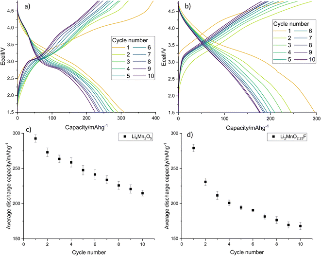
Electrochemical testing of Li4Mn2O5 and Li2MnO2.25F shows that they give an excellent average first cycle specific discharge capacity of 293 and 279 mA h g−1, respectively (Fig. 10, dQ/dV plots in Fig. S10†). Both materials experience a capacity fade resulting in a discharge capacity of 215 and 168 mA h g−1 after 10 cycles which corresponds to a 73.4 and 60.2% capacity retention. Capacity fade is very common for rocksalt type materials and materials synthesised using pristine reagents experience a similar capacity fade when processed similarly and cycled under comparable conditions (Fig. S11†).22,29 Furthermore, we have expanded this work to look at Na doping these Li–Mn–O systems, where 10% Na incorporation resulted in a significant improvement to the capacity retention (90.5% after 10 cycles, Fig. S12†). The results show that recovered LMO can successfully be upcycled into new cathode materials. This therefore provides a route to recycle these end-of-life LIB materials into a valuable product, especially if studies can be performed to improve the long-term performance of disordered rocksalt materials.
4. Conclusions
To summarise, this work reports a novel method to selectively leach low value Mn based cathode from EOL EV batteries and then upcycle into new cathode materials, the first example of this approach to synthesise high voltage spinel and disordered rocksalt phases. In contrast to previous studies, this work investigated LIB material obtained from a EOL EV which shows that this method is viable for such degraded cathode material sources. Citric acid has been shown to work as a selective leaching agent to separate cathodes containing LMO and NCA. As a development from previous work on ascorbic acid leaching, this work avoided the use of a pre-treatment NaOH delamination step and instead used citric acid as a combined leaching and delaminating acid. Recovered LMO was upcycled to form LMNO which gave a gravimetric discharge capacity of 119 mA h g−1. Recovered LMO was also used as a reagent to form Li4Mn2O5 and Li2MnO2.25F. These showed high gravimetric discharge capacities of 293 and 279 mA h g−1 respectively in line with previous reports for pristine materials. This work therefore illustrates the potential for recovered end of life battery materials to be manufactured into next generation cathode materials.Data availability
All data associated with this paper are openly available from: https://doi.org/10.25500/edata.bham.00001079.Conflicts of interest
There are no conflicts to declare.Acknowledgements
We would like to thank the Faraday Institution’s ReLiB and CATMAT projects (FIRG057 and FIRG063) for supporting this work. We would like to thank the Faraday Institution for the studentship funding of Rosie Madge (FITG021). We would like to thank Roberto Sommerville for disassembling the cells used in this study.References
- HM Government, Transitioning to Zero Emission Cars and Vans: 2035 Delivery Plan, 2021 Search PubMed.
- European Commission, Regulation (EU) 2023/1542 of the European Parliament and of the Council Concerning Batteries and Waste Batteries, 2023 Search PubMed.
- H.R.3684, Infrastructure Investment and Jobs Act, 117th Congress, 2021 Search PubMed.
- B. Makuza, Q. Tian, X. Guo, K. Chattopadhyay and D. Yu, J. Power Sources, 2021, 491, 229622 CrossRef CAS.
- D. Bian, Y. Sun, S. Li, Y. Tian, Z. Yang, X. Fan and W. Zhang, Electrochim. Acta, 2016, 190, 134–140 CrossRef CAS.
- Q. Meng, J. Duan, Y. Zhang and P. Dong, J. Ind. Eng. Chem., 2019, 80, 633–639 CrossRef CAS.
- X. J. Nie, X. T. Xi, Y. Yang, Q. L. Ning, J. Z. Guo, M. Y. Wang, Z. Y. Gu and X. L. Wu, Electrochim. Acta, 2019, 320, 134626 CrossRef CAS.
- P. Albertus, J. Christensen and J. Newman, J. Electrochem. Soc., 2009, 156, A606 CrossRef CAS.
- H. Y. Tran, C. Tacubert, M. Fleischhammer, P. Axmann, L. Kuppers and M. Wohlfahrt-Mehrens, J. Electrochem. Soc., 2011, 158, A556–A561 CrossRef CAS.
- H. Zou, E. Gratz, D. Apelian and Y. Wang, Green Chem., 2013, 15, 1183–1191 RSC.
- Q. Sa, E. Gratz, J. A. Heelan, S. Ma, D. Apelian and Y. Wang, J. Sustain. Metall., 2016, 2, 248–256 CrossRef.
- L. L. Driscoll, A. Jarvis, R. Madge, J. Price, R. Sommerville, F. S. Totini, M. Bahri, B. L. Mehdi, E. Kendrick, N. D. Browning, P. K. Allan, P. A. Anderson and P. R. Slater, ChemRxiv, 2023, preprint, DOI:10.26434/chemrxiv-2023-56rkk.
- K. S. Kim, M. K. Jeon, S. H. Song, S. Hong, H. S. Kim, S. W. Kim, J. Kim, P. Oh, J. Hwang, J. Song, J. Ma, J. J. Woo, S. H. Yu and H. Kim, J. Mater. Chem. A, 2023, 21222–21230 RSC.
- G. Qian, Z. Li, Y. Wang, X. Xie, Y. He, J. Li, Y. Zhu, S. Xie, Z. Cheng, H. Che, Y. Shen, L. Chen, X. Huang, P. Pianetta, Z. F. Ma, Y. Liu and L. Li, Cell Rep. Phys. Sci., 2022, 3, 100741 CrossRef CAS.
- H. Gao, Q. Yan, D. Tran, X. Yu, H. Liu, M. Li, W. Li, J. Wu, W. Tang, V. Gupta, J. Luo and Z. Chen, ACS Energy Lett., 2023, 4136–4144 CrossRef CAS.
- T. Wang, H. Luo, J. Fan, B. P. Thapaliya, Y. Bai, I. Belharouak and S. Dai, iScience, 2022, 25, 103801 CrossRef CAS PubMed.
- A. Manthiram, K. Chemelewski and E. S. Lee, Energy Environ. Sci., 2014, 7, 1339–1350 RSC.
- H. Geary, C. F. Elkjær, L. El Ouatani, J. Pezin, B. Ting, F. Flemming, J. W. Hedegaard and J. Højberg, Developing a High-Performance, Cobalt-free, 3 V Battery Cell, 2021 Search PubMed.
- Toshiba, 2024, https://www.global.toshiba/ww/technology/corporate/rdc/rd/topics/23/2311-02.html, accessed 12 February.
- L. Yang, B. Ravdel and B. L. Lucht, Electrochem. Solid-State Lett., 2010, 13, 6–9 Search PubMed.
- R. Amin, N. Muralidharan, R. K. Petla, H. Ben Yahia, S. A. Jassim Al-Hail, R. Essehli, C. Daniel, M. A. Khaleel and I. Belharouak, J. Power Sources, 2020, 467, 228318 CrossRef CAS.
- M. Freire, N. V. Kosova, C. Jordy, D. Chateigner, O. I. Lebedev, A. Maignan and V. Pralong, Nat. Mater., 2016, 15, 173–177 CrossRef CAS PubMed.
- J. Lee, D. H. Seo, M. Balasubramanian, N. Twu, X. Li and G. Ceder, Energy Environ. Sci., 2015, 8, 3255–3265 RSC.
- S. L. Glazier, J. Li, J. Zhou, T. Bond and J. R. Dahn, Chem. Mater., 2015, 27, 7751–7756 CrossRef CAS.
- I. Källquist, A. J. Naylor, C. Baur, J. Chable, J. Kullgren, M. Fichtner, K. Edström, D. Brandell and M. Hahlin, Chem. Mater., 2019, 31, 6084–6096 CrossRef.
- E. Zhao, L. He, B. Wang, X. Li, J. Zhang, Y. Wu, J. Chen, S. Zhang, T. Liang, Y. Chen, X. Yu, H. Li, L. Chen, X. Huang, H. Chen and F. Wang, Energy Storage Mater., 2019, 16, 354–363 CrossRef.
- R. Chen, S. Ren, M. Knapp, D. Wang, R. Witter, M. Fichtner and H. Hahn, Adv. Energy Mater., 2015, 5, 1–7 Search PubMed.
- J. Lee, J. K. Papp, R. J. Clément, S. Sallis, D. H. Kwon, T. Shi, W. Yang, B. D. McCloskey and G. Ceder, Nat. Commun., 2017, 8, 981 CrossRef PubMed.
- R. A. House, L. Jin, U. Maitra, K. Tsuruta, J. W. Somerville, D. P. Förstermann, F. Massel, L. Duda, M. R. Roberts and P. G. Bruce, Energy Environ. Sci., 2018, 11, 926–932 RSC.
- Z. Lun, B. Ouyang, Z. Cai, R. J. Clément, D. H. Kwon, J. Huang, J. K. Papp, M. Balasubramanian, Y. Tian, B. D. McCloskey, H. Ji, H. Kim, D. A. Kitchaev and G. Ceder, Chem, 2020, 6, 153–168 CAS.
- J. Marshall, D. Gastol, R. Sommerville, B. Middleton, V. Goodship and E. Kendrick, Metals, 2020, 10, 1–22 CrossRef.
- F. Ulu Okudur, S. K. Mylavarapu, M. Safari, D. De Sloovere, J. D'Haen, B. Joos, P. Kaliyappan, A. S. Kelchtermans, P. Samyn, M. K. Van Bael and A. Hardy, J. Alloys Compd., 2022, 892, 162175 CrossRef CAS.
- B. H. Toby and R. B. Von Dreele, J. Appl. Crystallogr., 2013, 46, 544–549 CrossRef CAS.
- J. S. O. Evans, Mater. Sci. Forum, 2010, 651, 1–9 Search PubMed.
- A. Coelho, J. Appl. Crystallogr., 2018, 51, 210–218 CrossRef CAS.
- K. Kanamura, H. Naito, T. Yao and Z. I. Takehara, J. Mater. Chem., 1996, 6, 33–36 RSC.
- K. W. Nam, W. S. Yoon, H. Shin, K. Y. Chung, S. Choi and X. Q. Yang, J. Power Sources, 2009, 192, 652–659 CrossRef CAS.
- H. Kondo, Y. Takeuchi, T. Sasaki, S. Kawauchi, Y. Itou, O. Hiruta, C. Okuda, M. Yonemura, T. Kamiyama and Y. Ukyo, J. Power Sources, 2007, 174, 1131–1136 CrossRef CAS.
- I. Belharouak, W. Lu, D. Vissers and K. Amine, Electrochem. commun., 2006, 8, 329–335 CrossRef CAS.
- R. Robert, C. Bunzli, E. J. Berg and P. Novák, Chem. Mater., 2015, 27, 526–536 CrossRef CAS.
- Y. Tesfamhret, H. Liu, Z. Chai, E. Berg and R. Younesi, ChemElectroChem, 2021, 8, 1516–1523 CrossRef CAS.
- M. Kunduraci, J. F. Al-Sharab and G. G. Amatucci, Chem. Mater., 2006, 18, 3585–3592 CrossRef CAS.
- G. Garhi, M. Aklalouch, C. Favotto, M. Mansori and I. Saadoune, J. Electroanal. Chem., 2020, 873, 114413 CrossRef CAS.
- A. Chen, L. Kong, Y. Shu, W. Yan, W. Wu, Y. Xu, H. Gao and Y. Jin, RSC Adv., 2019, 9, 12656–12666 RSC.
- L. L. Driscoll, E. H. Driscoll, B. Dong, F. N. Sayed, J. N. Wilson, C. A. O'Keefe, D. J. Gardner, C. P. Grey, P. K. Allan, A. A. L. Michalchuk and P. R. Slater, Energy Environ. Sci., 2023, 16, 5196–5209 RSC.
- B. Ouyang, N. Artrith, Z. Lun, Z. Jadidi, D. A. Kitchaev, H. Ji, A. Urban and G. Ceder, Adv. Energy Mater., 2020, 1903240, 1–11 Search PubMed.
- R. J. Clément, D. Kitchaev, J. Lee and G. Ceder, Chem. Mater., 2018, 30, 6945–6956 CrossRef.
Footnote |
| † Electronic supplementary information (ESI) available. See DOI: https://doi.org/10.1039/d4su00041b |
| This journal is © The Royal Society of Chemistry 2024 |

