 Open Access Article
Creative Commons Attribution 3.0 Unported Licence
Electrocatalytic hydrogenation of the formyl group and heteroaromatic ring in furfural on activated carbon cloth-supported ruthenium†
Meheryar R.
Kasad
 ab,
James E.
Jackson
 c and
Christopher M.
Saffron
 *ab
*ab
aDepartment of Chemical Engineering and Materials Science, Michigan State University, East Lansing, Michigan 48824, USA
bDepartment of Biosystems and Agricultural Engineering, Michigan State University, East Lansing, Michigan 48824, USA. E-mail: saffronc@msu.edu
cDepartment of Chemistry, Michigan State University, East Lansing, Michigan 48824, USA
First published on 19th August 2024
Abstract
Electrocatalytic hydrogenation (ECH) was explored as a mild technique (≤50 °C under atmospheric pressure) to produce valuable products from furfural, a promising biomass-derived platform chemical. In situ hydrogen equivalents made by water splitting were used to reduce the formyl group and saturate the heteroaromatic ring of furfural on an activated carbon cloth-supported ruthenium electrocatalyst. A systematic study was conducted to understand the relationship between the reaction conditions and the products. The factors analyzed include catholyte solution organic co-solvent content, catholyte solution acid content, and temperature. Acidity of the catholyte solution had the most significant effect on the yield of tetrahydrofurfuryl alcohol (THFA). The highest THFA yield was obtained in mildly acidic catholyte solutions (0.02 M HCl and 0.002 M HCl–0.02 M NaCl). The low carbon mole balance closure in the experiments was attributed to the side reactions of the reactants, intermediates, and products. The effects of current density on faradaic efficiency and of the functional groups attached to the furan ring on the formation of saturated heterocyclic products were also explored.
Sustainability spotlightProduction of carbon-based chemicals from agricultural residues provides a pathway for displacing fossil-derived products. In this context, the use of electrochemistry for achieving the required chemical transformations offers potential advantages such as operation at mild conditions, in situ production of reducing/oxidizing equivalents by harnessing renewable electricity, and amenability towards small-scale, localized applications. The present study investigated the electrocatalytic conversion of furfural that is commercially derived from pentosans in agricultural wastes such as corn cobs, to tetrahydrofurfuryl alcohol, a specialty solvent and intermediate, using a carbon-supported ruthenium electrocatalyst in a one-pot reactor. Importantly, this approach avoids utilization of hydrogen gas, derived from fossil resources in today's markets, and can be extended to saturation of heteroaromatic rings in several furanic compounds. Thus, the present study seeks to advance utilization of agricultural residues and electrification of processes within the chemical industry conforming with UN SDGs 9 (industry, innovation, and infrastructure) and 12 (responsible consumption and production). |
Introduction
Lignocellulosic biomass is a promising feedstock for sustainable production of biofuels, chemicals, and polymers that would reduce dependence on fossil resources. Furfural, commercially produced by acid catalyzed transformation of pentosans in agricultural residues such as corn cobs and sugarcane residue, is an example of a versatile chemical platform derived from lignocellulosic biomass.1 It has served as the basis for development of furan chemistry2 and is an important raw material for the derivation of several commercial furan compounds.3 Approximately 300 kton of furfural is produced globally per year4 and it has been identified by the U. S. Department of Energy as one of the ‘Top 30’ building block chemicals from sugars.5 Also found at 1–4 wt% in bio-oils,6 this widely studied model compound contains a carbonyl (formyl) group attached to a heteroaromatic (furan) ring. The formyl group, considered a source of bio-oil's chemical instability,7 is found in several other compounds, including formaldehyde, acetaldehyde, hydroxyacetaldehyde, glyoxal and methylglyoxal, that constitute 10–20 wt% of bio-oil.6Hydrogenation is used to produce a range of useful (tetrahydro)furanic products from furfural including furfuryl alcohol (FA), tetrahydrofurfuryl alcohol (THFA), 2-methylfuran (2-MF) and 2-methyltetrahydrofuran (2-MTHF). Among these, FA, THFA and 2-MTHF have been identified as furfural derivatives having considerable market size (>50 kton per year),8 which serves as a driving force to study the one-pot hydrogenation of furfural to these products. However, the conventional catalytic hydrogenation processes used to manufacture these products suffer from drawbacks such as the requirement for high hydrogen (H2) pressures and high temperatures. Furthermore, the hydrogen gas required by these processes is presently manufactured from fossil resources such as natural gas (via energy intensive reforming reactions) and coal, referred to as “grey” and “brown/black” hydrogen respectively.9 Electrocatalytic hydrogenation (ECH) is proposed as a mild alternative (<80 °C under atmospheric pressure) in which the required hydrogen equivalents are produced in situ by water splitting. Importantly, application of renewable electricity to generate “green” hydrogen equivalents during ECH circumvents utilization of fossil-derived hydrogen. Moreover, it enables storage of intermittently produced renewable electricity as chemical energy.10
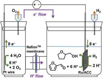
A typical ECH setup involves an electrolytic cell with two chambers separated by a membrane. Application of an electric potential splits water into oxygen gas, protons (H+ ions), and electrons (e−) at a catalytic anode under acidic conditions; the H+ ions then migrate across a proton exchange membrane (e.g., Nafion™) under the influence of the applied electric potential to a catalytic cathode where they combine with the electrons that migrate through the external circuit, driving cathodic reactions that produce the hydrogenated products.
Several investigators have studied the ECH of furfural using a variety of electrocatalytic cathode materials including supported and non-supported, base and noble metals such as Cu,10–24 Ni,10,11,13,14,18,20,21 Pt,10,13,14,21–23,25–27 Pd,11,17,18,25,26,28–30 Rh,11,17,18 Ru,11,18,31 Pb,10,13,19,21,22 Fe,10,13,20 Al,10,20 Zn,32 Au,33 Ag,33 and Co11,18 as well as alloys such as stainless steel,12,20 oxides such as TiO2,34 In2O3,35 Co3O4,35 Pb2Ru2O7−x,35 and La-doped TiO2,36 phosphides such as Cu3P and Ni2P,27 bimetallics such as NiCu,14,37 PtCo,38 and PdNiB,39 and carbon.10,12,13,15,33,40 Many of these studies have reported furfural transformation to FA, 2-MF and hydrofuroin by ECH, while only a few have reported conversion to the saturated heterocyclic (oxolane) products. Green et al. reported electrocatalytic conversion of furfural to THFA and 2-MTHF on a Pd/C electrocatalyst in a continuous flow cell at 1.75 V. The respective selectivities were 26% and 8%; however, only 6% of the furfural was converted to products.25 Furthermore, it was found that at 1.45 V the current density increased as temperature was raised from 30 °C to 70 °C. However, a decrease in current efficiency for furfural hydrogenation was noted signifying an increase in hydrogen gas production. Green et al. also reported conversion of furfural to THFA on a Pt/C electrocatalyst. Carl et al. reported conversion of furfural to 2-MTHF and THFA along with products such as tetrahydrofuran on hybrid cathodes composed of Pdblack and various loadings of Pd supported on alumina.28 Vapor phase experiments were conducted in a single-pass proton exchange membrane reactor. The highest selectivity for the oxolane products, THFA (∼9%) and 2-MTHF (∼50%), was obtained on an electrocatalyst comprised of Pdblack and 5 wt% Pd/Al2O3. Delima et al. investigated ECH of furfural in a flow reactor consisting of a Pd catalyst electrodeposited on a palladium membrane with an additional catalyst layer sputter-deposited on it.29 The requirement for dissolution of furfural in protic electrolytes was avoided by using a design where the electrochemical hydrogen generation and furfural hydrogenation were physically separated by a palladium membrane that also served as the cathode. The highest selectivities for FA (84%), THFA (98%) and 2-MTHF (14%) was obtained using Pt/Pd/Pd membranes albeit at different current densities, run times and sputter-deposited Pt layer thicknesses. More recently, Stankovic et al. used the same approach to demonstrate that high 2-MTHF selectivity (76%) was obtained at higher current densities (≥200 mA cm−2) when using Pd/Pd membranes.30 Lenk et al. demonstrated conversion of furfural to THFA on Pd, platinized Pt and glassy carbon cathodes coated with Pd and Pt inks.26 The highest THFA selectivity (15.3%) from furfural was observed for coated glassy carbon cathodes with Pd to![[thin space (1/6-em)]](https://www.rsc.org/images/entities/char_2009.gif) Pt ratio of 5
Pt ratio of 5![[thin space (1/6-em)]](https://www.rsc.org/images/entities/char_2009.gif) :
:![[thin space (1/6-em)]](https://www.rsc.org/images/entities/char_2009.gif) 1. Chamoulaud et al. reported conversion of furfural to THFA and 2-MTHF at low flow rates and/or high currents using a flow cell in which the cathode was prepared by plating copper on graphite felt.23 A few studies have also noted furfural conversion by ECH to ring-opened products: pentane-1,5-diol on Cu21 and Pb22 cathodes, and glutaraldehyde on a carbon cathode,40 although the yields were not quantified.
1. Chamoulaud et al. reported conversion of furfural to THFA and 2-MTHF at low flow rates and/or high currents using a flow cell in which the cathode was prepared by plating copper on graphite felt.23 A few studies have also noted furfural conversion by ECH to ring-opened products: pentane-1,5-diol on Cu21 and Pb22 cathodes, and glutaraldehyde on a carbon cathode,40 although the yields were not quantified.
The present study investigates the electrocatalytic conversion of furfural to the saturated heterocyclic products, THFA (and 2-MTHF), on ruthenium supported on activated carbon cloth (Ru/ACC). Activated carbon cloth (ACC) was selected as an electrocatalyst support for the present study due to its high surface area and electrical conductivity.41 THFA is conventionally manufactured by hydrogenation of FA on supported Ni catalysts at moderate temperatures (50–100 °C) in both liquid and vapor phase processes.42 It is used as a solvent, particularly for stripping and cleaning formulations, agricultural chemicals, dyes, and printing inks.43 An important application of THFA is in the manufacture of 3,4-dihydro-2H-pyran, a specialty chemical.44 DFT studies have shown that the flat η2 (C–O) configuration is favored for adsorption of furfural on ruthenium (Ru) surfaces, which activates pathways for both formyl group reduction and heteroaromatic ring saturation.45,46 Furthermore, Ru presents a cheaper alternative to both Pd and Pt that have been used in earlier studies on electrochemical transformation of furfural to saturated heterocyclic products. Conversion of furfural to THFA by catalytic hydrogenation on carbon-supported Ru (Ru/C) catalysts has been demonstrated previously by other groups.47–49 Moreover, ECH on Ru/ACC has been used by the Saffron group to successfully upgrade lignin-related phenolic model compounds50,51 and model lignin dimers52 to saturated compounds such as substituted cyclohexanols. Further, an ECH study in 2014 on the aqueous fraction of bio-oil using Ru/ACC noted conversion of its furfural content to THFA.53
In the present study, three factors were varied to assess furfural conversion and selectivity towards THFA by ECH: catholyte solution organic co-solvent (propan-2-ol) content, catholyte solution acid content, and temperature. A factorial experiment design was implemented to investigate the effects of individual factors as well as their interactions on THFA yield. Propan-2-ol, widely used as a solvent for furfural hydrogenation,54 was expected to affect product yields by influencing the distribution of reactants and products between the cathode surface and the catholyte solution. Moreover, an influence of solvents on product selectivity has been reported for catalytic hydrogenation of furfural.55–57 The acidity of the catholyte solution was expected to vary the yields of different hydrogenation products via both cathode surface effects and promotion of side reactions in the catholyte solution, while higher temperatures would enhance conversion and product yields due to more rapid surface reaction kinetics. The carbon mole balance, faradaic efficiency for the desired transformation and THFA yield were also determined under different conditions in follow-up experiments to enable derisking of the electrocatalytic route for conversion of furfural to THFA. Finally, production of saturated heterocycles by ECH of 2-substituted furans (2 MF, FA and 2-furoic acid) was investigated.
Experimental
Electrocatalyst preparation
The Ru/ACC electrocatalyst was prepared using the technique described by Li et al.50 Briefly, activated carbon cloth (Zorflex®∼Double Weave Activated Carbon Fiber Cloth, Charcoal House, Crawford, NE) was cut into 1.5 cm × 3.0 cm pieces. The pieces were immersed in deionized (DI) water overnight and then oven dried at 150 °C for 1 hour. Subsequently the dried pieces were soaked in a 3![[thin space (1/6-em)]](https://www.rsc.org/images/entities/char_2009.gif) :
:![[thin space (1/6-em)]](https://www.rsc.org/images/entities/char_2009.gif) 20 (volume fraction) solution of aqua ammonia (28.0–30.0% NH3) and DI water containing 6.4 wt% hexaammineruthenium(III) chloride [Ru(NH3)6Cl3] for 1 min to saturate the pores. The soaked pieces were dabbed against Kimwipes® to remove the excess solution. The ACC pieces impregnated with Ru were dried overnight at ambient conditions and subsequently vacuum dried for 24 h. The vacuum dried Ru/ACC was then reduced using the electrochemical reduction technique described by Garedew.58 The reduction was carried out in a divided H-cell, in which the two chambers were separated by a Nafion™ 117 membrane (Chemours, Wilmington, DE). 0.2 M hydrochloric acid (HCl) solution was used as the electrolyte in both compartments. The vacuum dried Ru/ACC was the cathode, while a platinum wire (99.95%; Strem Chemicals Newburyport, MA) served as the anode. The H-cell assembly was immersed in a heated water bath that was maintained at a temperature of 60 °C. The current was turned on immediately after immersing the Ru/ACC in the catholyte solution. The Ru/ACC was reduced using a current of 150 mA for approximately 1.5 h. The catholyte solution turned pink upon immersion of the Ru/ACC indicating leaching of the Ru salt. Under the influence of the reduction potential, the color initially changed to light yellow in the first few minutes and subsequently changed to dark blue. The blue color of the catholyte solution then gradually cleared resulting in a silver-grey deposition on the ACC which represented the end point of the electrochemical reduction. The color changes of the catholyte solution are attributed to the different oxidation states of Ru as it undergoes reduction and deposition on the activated carbon cloth fibers. The reduced Ru/ACC (referred to as Ru/ACC more generally) was then stored in a drying cabinet (∼55 °C) before being used for ECH experiments. A photograph of the Ru/ACC is provided in Fig. S1 of the ESI (ESI).†
20 (volume fraction) solution of aqua ammonia (28.0–30.0% NH3) and DI water containing 6.4 wt% hexaammineruthenium(III) chloride [Ru(NH3)6Cl3] for 1 min to saturate the pores. The soaked pieces were dabbed against Kimwipes® to remove the excess solution. The ACC pieces impregnated with Ru were dried overnight at ambient conditions and subsequently vacuum dried for 24 h. The vacuum dried Ru/ACC was then reduced using the electrochemical reduction technique described by Garedew.58 The reduction was carried out in a divided H-cell, in which the two chambers were separated by a Nafion™ 117 membrane (Chemours, Wilmington, DE). 0.2 M hydrochloric acid (HCl) solution was used as the electrolyte in both compartments. The vacuum dried Ru/ACC was the cathode, while a platinum wire (99.95%; Strem Chemicals Newburyport, MA) served as the anode. The H-cell assembly was immersed in a heated water bath that was maintained at a temperature of 60 °C. The current was turned on immediately after immersing the Ru/ACC in the catholyte solution. The Ru/ACC was reduced using a current of 150 mA for approximately 1.5 h. The catholyte solution turned pink upon immersion of the Ru/ACC indicating leaching of the Ru salt. Under the influence of the reduction potential, the color initially changed to light yellow in the first few minutes and subsequently changed to dark blue. The blue color of the catholyte solution then gradually cleared resulting in a silver-grey deposition on the ACC which represented the end point of the electrochemical reduction. The color changes of the catholyte solution are attributed to the different oxidation states of Ru as it undergoes reduction and deposition on the activated carbon cloth fibers. The reduced Ru/ACC (referred to as Ru/ACC more generally) was then stored in a drying cabinet (∼55 °C) before being used for ECH experiments. A photograph of the Ru/ACC is provided in Fig. S1 of the ESI (ESI).†
Electrocatalyst characterization
The surface area and pore volume were determined by nitrogen physisorption at 77 K (Micromeritics® 2020 ASAP). The samples were outgassed for 24 h at 130 °C prior to the analysis.Scanning electron microscopy (SEM) was used to determine the morphology of the support (ACC) and the electrocatalyst (Ru/ACC). The images were collected on a JSM-6610 LV (JEOL Ltd) scanning electron microscope. Energy dispersive X-ray spectroscopy (elemental analysis) was performed using an Oxford Instruments AZtec system (Oxford Instruments, High Wycomb, Bucks, England), software version 3.3 using a 20 mm2 Silicon Drift Detector (JSM-6610LV) and an ultra-thin window.
X-ray photoelectron spectroscopy (XPS) was performed on a Physical Electronics PHI 5600 instrument equipped with a monochromatic Al source. The spectra were calibrated using the C 1s peak at 285 eV. Data analysis was performed with the CasaXPS software.
The Ru content of the Ru/ACC electrocatalyst was determined by Inductively Coupled Plasma-Optical Emission Spectroscopy (ICP-OES). The analysis was conducted on an Agilent 5800 ICP-OES instrument equipped with AVS 6/7 and SPS 4 Autosampler. The samples were digested in concentrated nitric acid using the CEM Mars 6 Microwave Digestion System. Calibration solutions were prepared from a ruthenium(III) chloride (RuCl3) standard solution (Inorganic Ventures, Christiansburg, VA).
ECH setup
ECH experiments were conducted in batch mode using a glass H-cell fabricated by the Chemistry Glass Shop at Michigan State University (East Lansing, MI). The two chambers were separated by a Nafion™ 117 membrane (Chemours, Wilmington, DE). Ru/ACC was the cathode, while a platinum wire was the anode. Fig. 1 is a schematic representation of the ECH setup.An aqueous HCl solution with or without the organic co-solvent, propan-2-ol, was used as the catholyte solution while the anolyte solution consisted of an aqueous phosphoric acid (H3PO4) solution with the concentration of H3PO4 adjusted to match the pH of the catholyte solution. The H-cell assembly was immersed in a heated water bath to maintain the desired temperature. The Ru/ACC electrocatalyst was subjected to pre-electrolysis at 80 mA for 10 min, after which the requisite amount of the substrate stock solution was added to the cathode compartment resulting in a catholyte solution with a furanic substrate concentration of 0.02 M at the start of a trial. Both compartments contained 13 ml of electrolyte solution. A Xantrex XHR 300–3.5 DC power supply provided constant electric current throughout the trial.
Factorial experiment design
A duplicated factorial experimental design with three replicates at the center point was implemented to study the effects and interactions of three factors, catholyte solution organic co-solvent (propan-2-ol) content [A], catholyte solution acid content [B] and temperature [C], on the THFA yield from furfural ECH on the Ru/ACC electrocatalyst. Two levels of the propan-2-ol concentration in the catholyte solution, 0% and 20% (volume fraction), were arbitrarily selected. Prior studies on ECH of furfural have reported that the catholyte solution acid content, particularly at very low pH values, significantly affects the yield of different ECH products.19,24 Two HCl concentrations, 0.02 M and 0.16 M, and two temperature levels, 25 °C and 50 °C, were selected for investigation. The experimental conditions corresponding to each factor and relevant levels are summarized in Table 1.| Factor [code] | Level | ||
|---|---|---|---|
| Low (−1) | Center (0) | High (+1) | |
| Catholyte solution propan-2-ol content [A] | 0% (volume fraction) | 10% (volume fraction) | 20% (volume fraction) |
| Catholyte solution acid content [B] | 0.02 M HCl | 0.06 M HCl | 0.16 M HCl |
| Temperature [C] | 25 °C | 37 °C | 50 °C |
Sample analysis
Catholyte solution samples collected at the end of each trial were saturated with sodium chloride (NaCl) and extracted into dichloromethane (DCM). 1.00 ml of catholyte solution was saturated with 400 mg NaCl and extracted with 2.0 ml DCM. The cathode (Ru/ACC) was also extracted in DCM (5.0 ml) and the extracts were analyzed using gas chromatography-mass spectrometry (GC-MS) on a Shimadzu QP-5050A instrument. Standard solutions of furfural, FA, THFA, 2-MTHF, δ-valerolactone, 2-furoic acid and tetrahydro-2-furoic acid in DCM were used to construct calibration curves to quantify the sample concentrations. The sample concentrations were then used to compute the reactant conversion, yields of different products, and faradaic efficiency, and to check closure of the carbon mole balance.Calculations
where, {Reactant}0 is the amount of reactant at the start of a trial (time, t = 0) (in mol). {Reactant}t is the amount of reactant that remains unreacted at the end of a trial (in mol). {Productk}t is the amount of product k formed at the end of a trial (in mol). Faraday's constant, F = 96
![[thin space (1/6-em)]](https://www.rsc.org/images/entities/char_2009.gif) 485.3 C mol−1. nk is the number of electrons (e−) required to form product k. I is the current. t is the trial run-time.
485.3 C mol−1. nk is the number of electrons (e−) required to form product k. I is the current. t is the trial run-time.
Results and discussion
Electrocatalyst characterization
The washed and dried ACC and Ru/ACC were characterized by nitrogen (N2) physisorption at 77 K. BET surface area (SBET) was computed in the relative pressure range (p/p0 < 0.06; where p is the equilibrium pressure and p0 is the saturation vapor pressure) determined using the criteria developed by Rouquerol et al.59 for microporous adsorbents. The total pore volume (Vt) was estimated from the amount of vapor adsorbed at relative pressure close to unity based on the Gurvich rule.60 The micropore volume (Vμpore) was determined using the Dubinin–Radushkevich equation61 in the following relative pressure range: 10−4 < p/p0 < 0.02. The average pore width (Dp) was calculated using the equation: Dp = 4Vt/SBET. The results are summarized in Table 2 and the N2 physisorption isotherm for Ru/ACC is shown in Fig. S2.† The comparatively lower BET surface area, total pore volume and micropore volume of Ru/ACC indicates that some of the pores on the ACC were blocked due to electrochemical deposition of Ru.| S BET (m2 g−1) | V t (cm3 g−1) | V μpore (cm3 g−1) | D p (nm) | |
|---|---|---|---|---|
| Washed and dried ACC | 1090 | 0.476 | 0.414 | 1.74 |
| Ru/ACC | 928 | 0.412 | 0.352 | 1.78 |
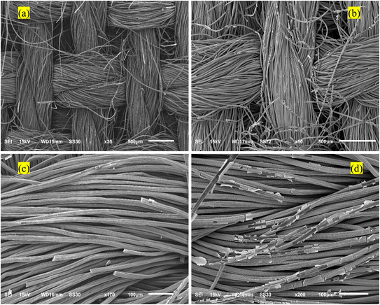
SEM images of the washed and dried ACC and Ru/ACC are shown in Fig. 2. It was observed that electrochemical reduction resulted in the deposition of a uniform Ru coating on the activated carbon cloth fibers, as seen in Fig. 2(b) and (c). However, there were some regions, close to the edges of the Ru/ACC sample, where the Ru coating appeared to have peeled off from individual fibers, as seen in Fig. 2(d). This effect may be attributed to the non-uniform current in these regions. The elemental map acquired by EDS (Fig. S3†) revealed a uniform dispersion of Ru on the activated carbon cloth fibers.
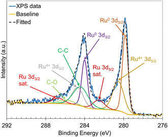
XPS was used to probe the surface chemistry of the Ru/ACC electrocatalyst. The Ru 3d and C 1s core level spectra are shown in Fig. 3. Deconvolution of the Ru 3d and C 1s spectra revealed the presence of Ru0 and Ru4+. The peaks at 279.8 eV and 284.0 eV were assigned to Ru0 (metallic state), while the peaks at 280.6 eV and 284.7 eV were associated with Ru4+ (in RuO2).62 The peaks at 284.4 eV and 285.9 eV corresponded to C–C and C–O, respectively. Overall, the XPS analysis demonstrated that a major fraction of Ru deposited on the ACC support was in the metallic state, which indicated that Ru in the precursor salt [Ru(NH3)6Cl3] was reduced by the electrochemical treatment. The re-oxidation of reduced Ru in catalytic materials upon exposure to air has been reported63–65 and might explain the presence of Ru4+ (RuO2). Further, it is possible that RuO2 may undergo reduction to the metallic form under the influence of the reduction potential applied during ECH.
The Ru loading on the ACC support was determined by ICP-OES. Ru/ACC samples were subjected to microwave digestion in concentrated nitric acid (HNO3) at 230 °C. A solid residue was obtained upon digestion of the Ru/ACC samples indicating that the samples were not completely dissolved in the acid. A solid residue was also obtained after digestion of the Ru/ACC samples in HCl–HNO3 mixtures. However, no solid residue was observed upon digestion of the washed and dried ACC (with no Ru) samples in HNO3 indicating that the residual solids obtained upon digestion of Ru/ACC contained Ru. These observations are consistent with the reported literature where it has been shown that Ru (particularly, Ru metal and anhydrous RuO2) is not completely recovered by acid digestion, even in aqua regia.66,67 Nonetheless, analysis of the HNO3 solutions obtained after separating the residual solids revealed a Ru loading of 1.39 wt% (±0.04 wt% std. error). Note that the reported loading does not account for the Ru present in the residual solids. The vacuum dried Ru/ACC samples that had not been subjected to electrochemical reduction were also digested in HNO3 at 230 °C. Importantly, no residual solids were observed upon digestion of the unreduced, vacuum dried Ru/ACC samples. The Ru loading determined by analysis of the HNO3 solution was 4.30 wt% (±0.70 wt% std error). Even though the reported Ru loading for the unreduced, vacuum dried Ru/ACC does not account for losses during electrochemical reduction, it represents an upper bound for the expected Ru loading on electrochemically reduced Ru/ACC. Digestion of Ru/ACC by a fusion method66 could be considered for more accurate determination of Ru loading in future investigations.
ECH of furfural on Ru/ACC
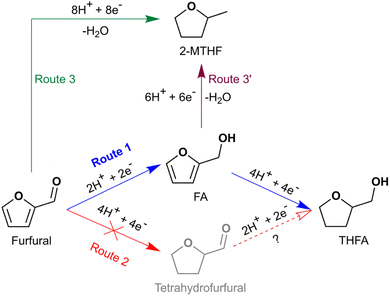
Hydrogenation of both the formyl group and the heteroaromatic ring in furfural to produce THFA (and 2-MTHF) by ECH was successfully demonstrated on an Ru/ACC electrocatalyst. The hydrogenation of furfural to THFA may proceed via two pathways as shown in Scheme 1: first, hydrogenation of the formyl group (–C(H)![[double bond, length as m-dash]](https://www.rsc.org/images/entities/char_e001.gif) O) to form FA followed by heteroaromatic ring saturation; or second, heteroaromatic ring saturation to tetrahydrofurfural followed by hydrogenation of the formyl group. DFT calculations by Banerjee and Mushrif (B&M) have indicated that for vapor phase reactants and products, the reaction may proceed via either pathway on Ru since the free energy barriers of the rate limiting steps along both pathways are comparable.45 Significant quantities of FA and no tetrahydrofurfural were observed after passage of 100 mA of current for 2 h under different conditions, suggesting that ECH of furfural on Ru/ACC proceeds via the former pathway. Studies by Merat et al.49 and Ordomsky et al.68 have proposed a similar pathway for formation of THFA during liquid phase furfural hydrogenation on Ru/C catalysts. The B&M DFT calculations also indicated that vapor phase hydrodeoxygenation of furfural to 2-MTHF in the presence of a Ru catalyst proceeds via formation of 2-MF; importantly, this transformation is unlikely to involve an FA intermediate.45 No 2-MF was detected by GC-MS although traces of 2-methyl-4,5-dihydrofuran (identified by matching the mass spectrum with the built-in NIST library) were detected in experiments with significant 2-MTHF formation. Information on the conditions required to produce significant quantities of 2-MTHF from furfural is included in the ESI.†
O) to form FA followed by heteroaromatic ring saturation; or second, heteroaromatic ring saturation to tetrahydrofurfural followed by hydrogenation of the formyl group. DFT calculations by Banerjee and Mushrif (B&M) have indicated that for vapor phase reactants and products, the reaction may proceed via either pathway on Ru since the free energy barriers of the rate limiting steps along both pathways are comparable.45 Significant quantities of FA and no tetrahydrofurfural were observed after passage of 100 mA of current for 2 h under different conditions, suggesting that ECH of furfural on Ru/ACC proceeds via the former pathway. Studies by Merat et al.49 and Ordomsky et al.68 have proposed a similar pathway for formation of THFA during liquid phase furfural hydrogenation on Ru/C catalysts. The B&M DFT calculations also indicated that vapor phase hydrodeoxygenation of furfural to 2-MTHF in the presence of a Ru catalyst proceeds via formation of 2-MF; importantly, this transformation is unlikely to involve an FA intermediate.45 No 2-MF was detected by GC-MS although traces of 2-methyl-4,5-dihydrofuran (identified by matching the mass spectrum with the built-in NIST library) were detected in experiments with significant 2-MTHF formation. Information on the conditions required to produce significant quantities of 2-MTHF from furfural is included in the ESI.†
Factorial experiment design
Nearly complete conversion of furfural, ≥95%, was obtained under all conditions after passing 100 mA of current for 2 h (∼29 mol e− per mol furfural). The results are summarized in Fig. S4.† FA and THFA were the major products under all conditions. Trace amounts of 2-MTHF and the ring-opened products pentan-1-ol and pentane-1,2-diol were also formed under all conditions. The ring-opened products were identified by matching their mass spectra with the built-in NIST library. The yields of the products produced in trace quantities were not quantified.The carbon mole balance and faradaic efficiency were computed based on three compounds, the reactant furfural and the two major products, FA and THFA, which were quantified using GC-MS. The highest carbon mole balance closure, 60%, was obtained at the −1,−1,−1 conditions while the lowest closure, 27%, was obtained at the +1,+1,+1 conditions. Low faradaic efficiencies, <12%, were obtained under all conditions. It is noted that carbon mole balances and faradaic efficiencies would be marginally higher than the reported values if the yields of trace products such as 2-MTHF had been quantified. Other investigations on ECH of furfural in batch mode20,24 have also reported similarly low carbon mole balance closures. The low carbon mole balance closures may be attributed to three major factors, namely, undesired side reactions, losses due to migration of a species to the anode compartment, and evaporation. Jung and Biddinger identified two types of undesired side reactions that occur during ECH of furfural: acid promoted homogeneous reactions and electron transfer mediated polymerization reactions.24,69 The higher molecular weight products (polymeric compounds) expected from both these reactions are not detected by GC-MS. It is noted that in the context of the present investigation the term ‘acid promoted side reactions’ includes acid catalyzed degradation/polymerization reactions of both substrates adsorbed to Ru/ACC (or ACC) and the Nafion™ membrane and substrates present in the catholyte solution.
Analysis of the DCM extracts of the anolyte solution at the end of the experimental runs confirmed that small quantities of reactant and products migrated to the anode compartment, though the low levels suggested that other loss mechanisms were dominant. Moreover, the hydrodeoxygenated products, 2-MF and 2-MTHF, have low boiling points at atmospheric pressure, 63.2–65.6 °C and 80.2 °C, respectively,43 which suggests that their evaporative loss from the system could be significant, especially in the experiments run at 50 °C.
The yield of THFA served as the basis for analysis of the factorial design. The analysis of variance (ANOVA) in Table S1† identified only one statistically significant factor, catholyte solution acid content, at a 95% confidence level. None of the other factors or higher order interactions significantly affected the yield of THFA. Furthermore, it was determined by the center point analysis that curvature was insignificant, confirming the absence of a maximum for the THFA yield within the ranges of the factors analyzed. Based on the results presented, to maximize yield of THFA, ECH of furfural must be carried out at low temperature (25 °C) in a catholyte solution with low acid content (relatively high pH) and no organic co-solvent (propan-2-ol). The experimental conditions that resulted in the highest yield or selectivity of THFA (or 2-MTHF) in various studies are summarized in Table S2.† Although the temperature does not significantly affect the yield of THFA, operating at lower temperatures at commercial scale would reduce both costs associated with heating and lowered yields due to evaporative losses. The decision regarding use of the organic co-solvent, propan-2-ol, is more complicated. For example, in experiments run at 25 °C in 0.16 M HCl solution without propan-2-ol, the reaction products, FA and THFA, were equally distributed between the Ru/ACC and the catholyte solution, but when the catholyte solution contained 20% propan-2-ol (volume fraction), more than 90% of the products were present in the catholyte solution. At larger scales, using a co-solvent adds costs associated with its downstream separation and recovery. Further, the faradaic efficiency would be reduced if active sites are blocked by the organic co-solvent. However, when co-solvent is not used, a greater fraction of the products would remain adsorbed to the cathode, presenting a significant challenge with respect to product recovery for processes operating in continuous mode. In such situations, the electrocatalyst would have to be periodically regenerated to recover the products. Additionally, the adsorbed products may occlude active sites over long operation times reducing electrocatalyst performance.
Control experiments
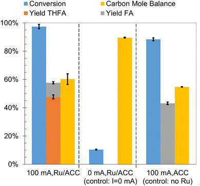
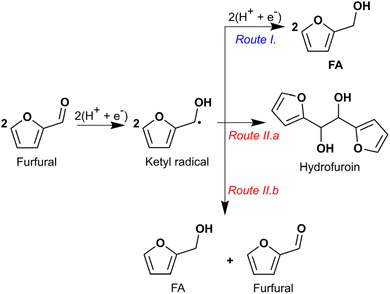
To establish the role of electric current and the catalytic effect of Ru supported on ACC in furfural ECH, control experiments were run for 2 h in 0.02 M aqueous HCl solution at 25 °C. The results are summarized in Fig. 4. No furfural hydrogenation products were detected when the experiment was carried out in the absence of electric current (i.e., no potential difference was applied across the electrodes) even though an Ru/ACC cathode was immersed in the catholyte solution; thus, electric current was necessary to generate the hydrogen equivalents required for furfural reduction. The incomplete carbon mole balance closure, 90%, in the absence of current flow supports the hypothesis that acid promoted side reactions decreased furfural availability for the desired reaction. The acid catalyzed degradation of furfural has been a subject of several investigations.70–72 A recent study by Almhofer et al. proposed two distinct acid catalysis pathways for furfural polymerization based on the site of proton attack, i.e., C2 and C5.73 Although the high temperature (>100 °C) conditions of these studies were not replicated in the present investigation, the accumulation of furfural on the Ru/ACC surface by adsorption may have accelerated the degradation reaction kinetics.ECH of furfural on ACC without Ru (washed and dried ACC) produced FA, yield 43%, along with hydrofuroin and trace amounts of 2-MTHF. The formation of hydrofuroin was confirmed by matching the GC retention time and mass spectrum for the product obtained by reagent-based reduction of furoin with sodium borohydride (NaBH4). The result for furfural electroreduction on ACC is consistent with the non-catalytic electroreduction of furfural to FA on carbon cathodes reported by others10,12,13,40 and confirmed that Ru active sites were essential for heteroaromatic ring saturation to form THFA. Jung and Biddinger have suggested that promotion of FA polymerization by an electron transfer mediated process could explain the lower carbon mole balance closure under conditions where FA is the primary product.24 Additionally, Shang et al. found that in aqueous electrolytes (pH 0, 7 and 13), carbon paper cathodes showed higher selectivity towards hydrofuroin formation compared to copper foam cathodes which showed higher selectivity towards FA formation.15 Nilges and Schröder10 and Diaz et al.40 also identified hydrofuroin as the major product of furfural ECH on carbon cathodes in acidic media. Shang et al. attributed the difference in product selectivities to the less negative potential required for formation of an adsorbed hydrogen atom on copper as compared to carbon. Thus, on copper cathodes the ketyl radical [(C4H3O)C·(H)(OH)] underwent hydrogenation to produce FA whereas on carbon cathodes it underwent radical dimerization to produce hydrofuroin. The pathways for formation of FA and hydrofuroin are shown in Scheme 2.
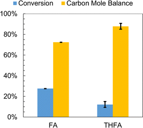
FA and THFA were also subjected to individual control experiments involving no passage of electric current through the H-cell for 2 h in 0.02 M aqueous HCl solution at 25 °C. The results are summarized in Fig. 5. An incomplete carbon mole balance closure, 72% and 68% respectively, was observed for both species. Similar to furfural, acid catalyzed polymerization of FA has also been the subject of several investigations.74–77 Thermochemistry calculations by Kim et al. indicate that acid catalyzed FA polymerization proceeds via protonation of the hydroxy group in FA leading to the formation of a carbenium ion [(C4H3O)C+(H)2] and water.78 An attack on the carbenium ion from the C5 position of FA with simultaneous removal of a proton resulted in the formation of a dimer containing a –CH2– bridge. Chain propagation involved reaction of carbenium ions with the oligomers. The formation of colored species was explained by a hydride ion shift from the oligomer to the carbenium ion followed by removal of a proton yielding a conjugated diene. Importantly, these polymerization reactions were shown to occur at room temperature in the presence of mineral acids. It was anticipated that THFA, being more stable due to its saturated nature, would not undergo such degradation/polymerization in the presence of mineral acids.43 Therefore, extraction efficiencies for furfural, FA and THFA from 0.02 M aqueous HCl solutions into DCM were computed to determine what fraction of the incomplete carbon mole balance closure was due to extraction losses from the catholyte solution. FA and THFA are completely miscible with water, while furfural has a finite solubility in water.3 Furfural and FA were completely recovered by extraction into DCM, but THFA was only partially recovered. However, even after accounting for the average extraction efficiency of THFA, 71% (±2% std error), the carbon mole balance could not be closed. It is noted that the extraction efficiency for THFA from the catholyte solution was used to correct only the relevant values reported in Fig. 5 and 6; similar corrections were not applied to values reported elsewhere.
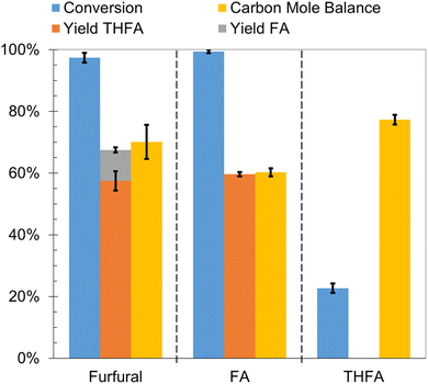
The furfural hydrogenation products, FA and THFA, were subjected to ECH on Ru/ACC in 0.02 M aqueous HCl solution by passing 100 mA current for 2 h at 25 °C. The results as compared to furfural ECH are summarized in Fig. 6. FA underwent nearly complete conversion, and THFA, yield 49%, was the primary product. No reduction products were observed following THFA ECH. Even after accounting for the THFA extraction efficiency, incomplete carbon mole balance closure was observed in both cases, 60% and 77% respectively. These losses were greater than those observed in control experiments involving no current passage indicating the occurrence of electrochemically caused side reactions. The control experiments on FA and THFA demonstrate that losses due to both acid promoted side reactions and electron transfer mediated side reactions were greater for FA than THFA. Furthermore, a purple coloration of the Nafion™ membrane in the region contacting the catholyte solution, as shown in Fig. S5,† is noted for experiments where FA was the reactant. This coloration indicates that FA interaction with the Nafion™ membrane likely represents another FA loss mechanism.
The mechanism for the electron transfer mediated side reactions is not well defined. However, a study by Staker provides some insights on the likely mechanism of such reactions during electrolytic reduction of furfural.79 Staker observed formation of a non-pinacolic dimer on a lead amalgam cathode, that has a high overpotential for hydrogen evolution. The proposed mechanism for dimer formation involved proton addition to the carbonyl oxygen in furfural leading to the formation of a carbenium ion [(C4H3O)C+(H)(OH)] which was then attacked from the C5 position of FA. Concomitant removal of a proton resulted in the formation of a dimer containing a –CHOH– bridge. It is hypothesized that in the present study such reactions occur on portions of the Ru/ACC electrocatalyst with no Ru deposition. Further investigation is required to establish detailed mechanisms for depletion of the compounds (furfural, FA and THFA) by electrochemical and acid promoted processes. Overall, based on the control experiments, the order of susceptibility to both acid promoted side reactions and electron transfer mediated side reactions is summarized as: FA > furfural ∼ THFA.
Effect of catholyte solution acid content
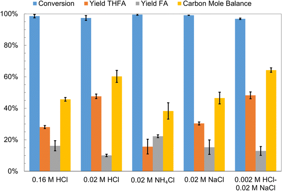
ECH of furfural was carried out in two different aqueous solutions, 0.02 M NH4Cl and 0.02 M NaCl, and the results were compared to those for ECH in 0.16 M HCl and 0.02 M HCl to further investigate the effects of catholyte solution acid content on the yields of different hydrogenation products. The results are summarized in Fig. 7. The conversion of furfural (initial concentration 0.02 M) was greater than 95% in all four electrolytes when 100 mA of current was passed for 2 h. The highest carbon mole balance closure, 60%, and THFA yield, 48%, were obtained in the 0.02 M HCl solution. THFA was also the major product in both 0.16 M HCl and 0.02 M NaCl solutions, although its yields, 28% and 30% respectively, were lower than those obtained in the 0.02 M HCl solution. Interestingly in the 0.02 M NH4Cl solution the major product was FA, yield 22%, and the carbon mole balance closure, 38%, was comparatively lower. The low yield of THFA in the NH4Cl solution may be attributed to electron transfer mediated side reactions which are likely favored by the more negative potential of the cathode and the relatively lower availability of protons in the NH4Cl solution as compared to the HCl solution. Furthermore, trace amounts of furfural amination products were observed in the Ru/ACC DCM extract following furfural ECH in the NH4Cl solution. Nishimura et al. have reported the reductive amination of furfural in aqueous ammonia on supported Ru catalysts under pressurized H2.80 The amination mechanism proposed by Nishimura et al. involved formation of a hydrofuramide intermediate that produced monomeric and dimeric amine compounds upon hydrogenolysis. However, other investigators have proposed that the amination reaction progresses via formation of a 2-furylmethanimine intermediate.81,82 The lower yield of THFA in the NaCl solution may be the result of an alternative mechanism for generation of the reactive hydrogen species. The reactive hydrogen species in neutral and basic electrolytes are produced by reduction of water that requires a more negative cathode potential which in turn may favor the electron transfer mediated side reactions. The lower carbon mole balance closure in 0.16 M HCl on the other hand may be attributed to the acid promoted side reactions that are likely to occur at significant rates in the more acidic catholyte solutions.The results of the above experiments suggest that there may exist a catholyte solution with an optimal pH obtained by using aqueous HCl solutions of concentration lower than 0.02 M where the rate of the side reactions is reduced, improving the yield of desired THFA. Therefore, ECH of furfural in a 0.002 M aqueous HCl solution was investigated. The high cell potential required due to the low conductivity of the 0.002 M HCl solution was avoided by addition of NaCl, concentration 0.02 M, as a supporting electrolyte in the catholyte solution. The concentration of H3PO4 solution in the anode compartment was adjusted to match the pH of the 0.02 M HCl solution. The results obtained were very similar to furfural ECH in the 0.02 M HCl solution suggesting that the electron transfer mediated side reactions were the primary cause for low carbon mole balance closures.
Effect of current density
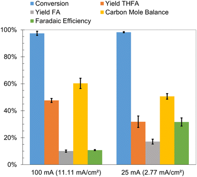
The faradaic efficiencies for the factorial design experiments, reported earlier, were less than 12%. Low faradaic efficiencies are a significant bottleneck for commercialization of ECH processes. Lowering the current density is one of the strategies used to suppress the hydrogen evolution reaction on the cathode. It was observed that decreasing the current from 100 mA (11.11 mA cm−2) to 25 mA (2.77 mA cm−2) led to a nearly three-fold increase in the faradaic efficiency, from 11% to 32% as shown in Fig. 8. The conversion of furfural was greater than 95% after 2 hours in both cases; however, the THFA yield was significantly lower and FA yield was only slightly higher at the lower current density. The lower carbon mole balance closure and THFA yield is attributed to the acid promoted side reactions and electron transfer mediated side reactions highlighted earlier. The rates of these side reactions may be enhanced due to the slow rate of FA hydrogenation to THFA at the lower current density. Thus, operating at the lower current density improved faradaic efficiency, but decreased the yield of desired THFA.Effects of functional groups attached to furan ring
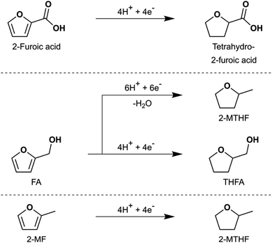
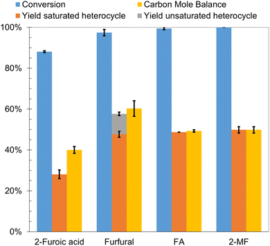
As an extension of the parametric studies, the effect of different functional groups (i.e., carboxyl, formyl, hydroxymethyl and methyl) attached to the furan ring on the formation of saturated heterocyclic products was investigated. The results for 2-furoic acid, FA, and 2-MF ECH were compared to those for furfural ECH. The experiments for 2-furoic acid, furfural and FA were carried out at 25 °C in a 0.02 M aqueous HCl solution; however, due to its low solubility in aqueous solutions, ECH of 2-MF was carried out in 0.02 M HCl solution with 20% propan-2-ol (volume fraction). Conversion greater than 85% was obtained for all substrates after passing 100 mA of current for 2 h. The observed transformations are shown in Scheme 3 and the results are summarized in Fig. 9. FA was primarily converted to THFA, yield 49%, with trace amounts of 2-MTHF, pentan-1-ol and pentane-1,2-diol. The low carbon mole balance closure was attributed to the acid promoted and electron transfer mediated side reactions highlighted earlier. ECH of 2-MF primarily produced 2-MTHF, yield 50%, along with trace amounts of pentan-1-ol and pentan-2-ol. Acid promoted side reactions of 2-MF are believed to be the primary cause for poor carbon mole balance closure.24 In fact, Ishigaki and Shono have demonstrated formation of a tetramer by treatment of 2-MF with phosphoric acid.83 Tetrahydro-2-furoic acid, yield 28%, was the major product of 2-furoic acid ECH. A small quantity of δ-valerolactone (δVL), yield ∼1%, was also produced indicating the occurrence of ring opening reactions. Asano et al. proposed that δVL formation during 2-furoic acid hydrogenation on Pt/Al2O3 occurs via a mechanism involving furan ring opening by C–O dissociation at the 1,2 position followed by saturation of the carbon–carbon double bonds on the open chain and intramolecular dehydration to form the ester product.84 The recalcitrance of the carboxyl group to reduction during ECH is consistent with the study by Fukazawa et al. that demonstrated transformation of 4-substituted benzoic acids to cyclohexanecarboxylic acids by ECH on Ketjenblack supported noble metals (Pt, Rh and Ru) and bimetallics (PtRu).85 The poor carbon mole balance closure in 2-furoic acid ECH experiments could be attributed to side reactions that produce higher molecular weight products that are not detectable by GC-MS. However, due to the limited literature available on this topic we are unable to speculate on the mechanisms of these side reactions. The transformation of 2-furoic acid to tetrahydro-2-furoic acid by an electrocatalytic pathway has not been demonstrated previously to the best of our knowledge. More importantly, the conversion of 2-furoic acid to tetrahydro-2-furoic acid demonstrates that reduction of the oxygenated functional group attached to the furan ring is not a pre-condition for saturation of the heteroaromatic ring.Conclusions
Electrocatalytic conversion of furfural to THFA was successfully demonstrated on an activated carbon cloth-supported ruthenium electrocatalyst. Acidity of the catholyte solution had a significant effect on the yield of THFA. The highest yields of THFA were obtained in mildly acidic catholyte solutions (0.02 M HCl and 0.002 M HCl–0.02 M NaCl), while a strongly acidic catholyte solution (0.92 M HCl) and higher temperature (50 °C) were necessary to produce a significant amount of 2-MTHF. Low carbon mole balance closures were obtained at all conditions indicating the significant extent of side reactions involving the reactant, furfural, the intermediate, FA, and the product, THFA. Notwithstanding the improvement in faradaic efficiency for experiments run at lower current density, it is recommended that relatively higher current densities be applied to maximize the yield of the desired product, THFA, by minimizing the amount of intermediate, FA, available for participation in the side reactions. Finally, the reduction of 2-MF, FA and 2-furoic acid to 2-MTHF, THFA and tetrahydro-2-furoic acid, respectively, demonstrated the activity of Ru towards catalyzing the heteroaromatic ring saturation by ECH. Overall, the modest desired product yields indicate that investigation of the side reactions, particularly electron transfer mediated reactions, is important future work.Data availability
The data supporting this study have been included in the article and the ESI.†Conflicts of interest
There are no conflicts to declare.Acknowledgements
This work was funded by the National Science Foundation under award number 2055068. Dr Saffron's contribution was supported in part by the USDA National Institute of Food and Agriculture, Hatch Project 1018335, and Michigan State University AgBioResearch. Elemental analysis (ICP-OES) was performed at the Michigan State University Quantitative Bio-Element Analysis and Mapping (QBEAM) Center. The authors warmly acknowledge the assistance provided by Abigail Vanderberg (SEM-EDS), Dr Per Askeland (XPS) and Dr Sue Aaron (ICP-OES).References
- J. Hidalgo-Carrillo, A. Marinas and F. J. Urbano, in Furfural, ed. D. M. Alonso and M. L. Granados, World Scientific, 2018, ch. 1, pp. 1–30 Search PubMed.
- B. Kamm, M. Kamm, P. R. Gruber and S. Kromus, in Biorefineries-Industrial Processes and Products, ed. B. Kamm, P. R. Gruber and M. Kamm, John Wiley & Sons, 2005, pp. 1–40 Search PubMed.
- R. H. Kottke, in Kirk-Othmer Encyclopedia of Chemical Technology, John Wiley & Sons, 2000 Search PubMed.
- R. Mariscal, P. Maireles-Torres, M. Ojeda, I. Sádaba and M. L. Granados, Energy Environ. Sci., 2016, 9, 1144–1189 RSC.
- T. Werpy and G. Petersen, Top Value Added Chemicals from Biomass: Volume I -- Results of Screening for Potential Candidates from Sugars and Synthesis Gas, United States, 2004 Search PubMed.
- A. Bridgwater, S. Czernik and J. Piskorz, in Progress in Thermochemical Biomass Conversion, ed. A. V. Bridgwater, John Wiley & Sons, 2001, ch. 80, pp. 977–997 Search PubMed.
- J. P. Diebold, A Review of the Chemical and Physical Mechanisms of the Storage Stability of Fast Pyrolysis Bio-Oils, United States, 1999 Search PubMed.
- K. Dalvand, J. Rubin, S. Gunukula, M. C. Wheeler and G. Hunt, Biomass Bioenergy, 2018, 115, 56–63 CrossRef.
- IEA, The Future of Hydrogen, IEA, Paris, 2019 Search PubMed.
- P. Nilges and U. Schröder, Energy Environ. Sci., 2013, 6, 2925–2931 RSC.
- E. Andrews, J. A. Lopez-Ruiz, J. D. Egbert, K. Koh, U. Sanyal, M. Song, D. S. Li, A. J. Karkamkar, M. A. Derewinski, J. Holladay, O. Y. Gutiérrez and J. D. Holladay, ACS Sustainable Chem. Eng., 2020, 8, 4407–4418 CrossRef CAS.
- Y. Cao and T. Noël, Org. Process Res. Dev., 2019, 23, 403–408 CrossRef CAS PubMed.
- L. C. Liu, H. H. Liu, W. M. Huang, Y. P. He, W. L. Zhang, C. N. Wang and H. B. Lin, J. Electroanal. Chem., 2017, 804, 248–253 CrossRef CAS.
- R. J. Dixit, K. Bhattacharyya, V. K. Ramani and S. Basu, Green Chem., 2021, 23, 4201–4212 RSC.
- X. Shang, Y. Yang and Y. J. Sun, Green Chem., 2020, 22, 5395–5401 RSC.
- N. Maselj, V. Jovanovski, F. Ruiz-Zepeda, M. Finšgar, T. Klemenčič, J. Trputec, A. R. Kamšek, M. Bele, N. Hodnik and P. Jovanovič, Energy Technol., 2023, 11, 2201467 CrossRef CAS.
- U. Sanyal, J. Lopez-Ruiz, A. B. Padmaperuma, J. Holladay and O. Y. Gutiérrez, Org. Process Res. Dev., 2018, 22, 1590–1598 CrossRef CAS.
- J. A. Lopez-Ruiz, E. Andrews, S. A. Akhade, M. S. Lee, K. Koh, U. Sanyal, S. F. Yuk, A. J. Karkamkar, M. A. Derewinski, J. Holladay, V. A. Glezakou, R. Rousseau, O. Y. Gutiérrez and J. D. Holladay, ACS Catal., 2019, 9, 9964–9972 CrossRef CAS.
- X. H. Chadderdon, D. J. Chadderdon, J. E. Matthiesen, Y. Qiu, J. M. Carraher, J.-P. Tessonnier and W. Li, J. Am. Chem. Soc., 2017, 139, 14120–14128 CrossRef CAS PubMed.
- Z. Li, S. Kelkar, C. H. Lam, K. Luczek, J. E. Jackson, D. J. Miller and C. M. Saffron, Electrochim. Acta, 2012, 64, 87–93 CrossRef CAS.
- B. Zhao, M. Y. Chen, Q. X. Guo and Y. Fu, Electrochim. Acta, 2014, 135, 139–146 CrossRef CAS.
- P. Parpot, A. P. Bettencourt, G. Chamoulaud, K. B. Kokoh and E. M. Beigsir, Electrochim. Acta, 2004, 49, 397–403 CrossRef CAS.
- G. Chamoulaud, D. Floner, C. Moinet, C. Lamy and E. M. Belgsir, Electrochim. Acta, 2001, 46, 2757–2760 CrossRef CAS.
- S. Jung and E. J. Biddinger, ACS Sustainable Chem. Eng., 2016, 4, 6500–6508 CrossRef CAS.
- S. K. Green, J. Lee, H. J. Kim, G. A. Tompsett, W. B. Kim and G. W. Huber, Green Chem., 2013, 15, 1869–1879 RSC.
- T. Lenk, V. Ruess, J. Gresch and U. Schröder, Green Chem., 2023, 25, 3077–3085 RSC.
- X. Zhang, M. M. Han, G. Q. Liu, G. Z. Wang, Y. X. Zhang, H. M. Zhang and H. J. Zhao, Appl. Catal., B, 2019, 244, 899–908 CrossRef CAS.
- S. Carl, K. Waldrop, P. Pintauro, L. T. Thompson and W. A. Tarpeh, ChemElectroChem, 2019, 6, 5563–5570 CrossRef CAS.
- R. S. Delima, M. D. Stankovic, B. P. MacLeod, A. G. Fink, M. B. Rooney, A. X. Huang, R. P. Jansonius, D. J. Dvorak and C. P. Berlinguette, Energy Environ. Sci., 2022, 15, 215–224 RSC.
- M. D. Stankovic, J. F. Sperryn, R. S. Delima, C. C. Rupnow, M. B. Rooney, M. Stolar and C. P. Berlinguette, Energy Environ. Sci., 2023, 16, 3453–3461 RSC.
- G. Bharath and F. Banat, ACS Appl. Mater. Interfaces, 2021, 13, 24643–24653 CrossRef CAS PubMed.
- M. S. Dhawan, G. D. Yadav and S. C. Barton, Sustainable Energy Fuels, 2021, 5, 2972–2984 RSC.
- M. Wolfsgruber, R. H. Bischof, C. Paulik, A. Slabon and B. V. M. Rodrigues, RSC Sustainability, 2024, 2, 1142–1153 RSC.
- D. Chu, Y. Hou, J. He, M. Xu, Y. Wang, S. Wang, J. Wang and L. Zha, J. Nanopart. Res., 2009, 11, 1805–1809 CrossRef CAS.
- R. J. Dixit, P. Gayen, S. Saha, B. S. De, A. Anand, S. Basu and V. K. Ramani, Ind. Eng. Chem. Res., 2024, 63, 5039–5052 CrossRef CAS.
- F. W. Wang, M. Xu, L. Wei, Y. J. Wei, Y. H. Hu, W. Y. Fang and C. G. Zhu, Electrochim. Acta, 2015, 153, 170–174 CrossRef CAS.
- R. J. Dixit, A. Singh, V. K. Ramani and S. Basu, React. Chem. Eng., 2021, 6, 2342–2353 RSC.
- L. Li, M. Yang, L. Cheng, J. Shi, J. Gou and J. Xu, React. Chem. Eng., 2023, 8, 2796–2803 RSC.
- M. A. Sabri, G. Bharath, A. B. Hai, M. Abu Haija, R. P. Nogueira and F. Banat, Fuel, 2023, 353 Search PubMed.
- L. A. Diaz, T. E. Lister, C. Rae and N. D. Wood, ACS Sustainable Chem. Eng., 2018, 6, 8458–8467 CrossRef CAS.
- M. E. Ramos, P. R. Bonelli and A. L. Cukierman, Colloids Surf., A, 2008, 324, 86–92 CrossRef CAS.
- K. Yan, G. S. Wu, T. Lafleur and C. Jarvis, Renewable Sustainable Energy Rev., 2014, 38, 663–676 CrossRef CAS.
- H. E. Hoydonckx, W. M. Van Rhijn, W. Van Rhijn, D. E. De Vos and P. A. Jacobs, in Ullmann's Encyclopedia of Industrial Chemistry, John Wiley & Sons, 2007 Search PubMed.
- P. Maireles-Torres and P. L. Arias, in Furfural, eds. D. M. Alonso and M. L. Granados, World Scientific, 2018, ch. 3.2, pp. 79–89 Search PubMed.
- A. Banerjee and S. H. Mushrif, ChemCatChem, 2017, 9, 2828–2838 CrossRef CAS.
- A. Banerjee and S. H. Mushrif, J. Phys. Chem. C, 2018, 122, 18383–18394 CrossRef CAS.
- N. S. Biradar, A. A. Hengne, S. N. Birajdar, R. Swami and C. V. Rode, Org. Process Res. Dev., 2014, 18, 1434–1442 CrossRef CAS.
- B. M. Matsagar, C. Y. Hsu, S. S. Chen, T. Ahamad, S. M. Alshehri, D. C. W. Tsang and K. C. W. Wu, Sustainable Energy Fuels, 2020, 4, 293–301 RSC.
- N. Merat, C. Godawa and A. Gaset, J. Chem. Technol. Biotechnol., 1990, 48, 145–159 CrossRef CAS.
- Z. Li, M. Garedew, C. H. Lam, J. E. Jackson, D. J. Miller and C. M. Saffron, Green Chem., 2012, 14, 2540–2549 RSC.
- M. Garedew, D. Young-Farhat, J. E. Jackson and C. M. Saffron, ACS Sustainable Chem. Eng., 2019, 7, 8375–8386 CrossRef CAS.
- M. Garedew, D. Young-Farhat, S. Bhatia, P. C. Hao, J. E. Jackson and C. M. Saffron, Sustainable Energy Fuels, 2020, 4, 1340–1350 RSC.
- Z. Li, S. Kelkar, L. Raycraft, M. Garedew, J. E. Jackson, D. J. Miller and C. M. Saffron, Green Chem., 2014, 16, 844–852 RSC.
- S. Chen, R. Wojcieszak, F. Dumeignil, E. Marceau and S. Royer, Chem. Rev., 2018, 118, 11023–11117 CrossRef CAS PubMed.
- J. Lee, J. Woo, C. Nguyen-Huy, M. S. Lee, S. H. Joo and K. An, Catal. Today, 2020, 350, 71–79 CrossRef CAS.
- M. Y. Byun and M. S. Lee, J. Ind. Eng. Chem., 2021, 104, 406–415 CrossRef CAS.
- M. Hronec and K. Fulajtarová, Catal. Commun., 2012, 24, 100–104 CrossRef CAS.
- M. Garedew, PhD Thesis, Michigan State University, 2018 Search PubMed.
- J. Rouquerol, P. Llewellyn and F. Rouquerol, in Characterization of Porous Solids VII, ed. P. L. Llewellyn, F. Rodriquez-Reinoso, J. Rouqerol and N. Seaton, Elsevier, 2007, vol. 160, pp. 49–56 Search PubMed.
- F. Rouquerol, J. Rouquerol and K. Sing, Adsorption by Powders and Porous Solids, Academic Press, London, 1999 Search PubMed.
- S. Lowell, J. E. Shields, M. A. Thomas and M. Thommes, in Characterization of Porous Solids and Powders: Surface Area, Pore Size and Density, Springer Netherlands, Dordrecht, 2004, pp. 129–156 Search PubMed.
- D. J. Morgan, Surf. Interface Anal., 2015, 47, 1072–1079 CrossRef CAS.
- P. G. J. Koopman, A. P. G. Kieboom and H. van Bekkum, J. Catal., 1981, 69, 172–179 CrossRef CAS.
- Y. Marco, L. Roldán, S. Armenise and E. García-Bordejé, ChemCatChem, 2013, 5, 3829–3834 CrossRef CAS.
- Q. Yuan, D. Zhang, L. v. Haandel, F. Ye, T. Xue, E. J. M. Hensen and Y. Guan, J. Mol. Catal. A: Chem., 2015, 406, 58–64 CrossRef CAS.
- T. Suoranta, M. Niemelä and P. Perämäki, Talanta, 2014, 119, 425–429 CrossRef CAS PubMed.
- M. Balcerzak, Crit. Rev. Anal. Chem., 2002, 32, 181–226 CrossRef CAS.
- V. V. Ordomsky, J. C. Schouten, J. van der Schaaf and T. A. Nijhuis, Appl. Catal., A, 2013, 451, 6–13 CrossRef CAS.
- S. Jung and E. J. Biddinger, Energy Technol., 2018, 6, 1370–1379 CrossRef CAS.
- B. Danon, L. van der Aa and W. de Jong, Carbohydr. Res., 2013, 375, 145–152 CrossRef CAS PubMed.
- I. C. Rose, N. Epstein and A. P. Watkinson, Ind. Eng. Chem. Res., 2000, 39, 843–845 CrossRef CAS.
- D. L. Williams and A. P. Dunlop, Ind. Eng. Chem., 1948, 40, 239–241 CrossRef CAS.
- L. Almhofer, R. H. Bischof, M. Madera and C. Paulik, Can. J. Chem. Eng., 2023, 101, 2033–2049 CrossRef CAS.
- S. Bertarione, F. Bonino, F. Cesano, S. Jain, M. Zanetti, D. Scarano and A. Zecchina, J. Phys. Chem. B, 2009, 113, 10571–10574 CrossRef CAS PubMed.
- M. Choura, N. M. Belgacem and A. Gandini, Macromolecules, 1996, 29, 3839–3850 CrossRef CAS.
- R. T. Conley and I. Metil, J. Appl. Polym. Sci., 1963, 7, 37–52 CrossRef CAS.
- H. Müller, P. Rehak, C. Jäger, J. Hartmann, N. Meyer and S. Spange, Adv. Mater., 2000, 12, 1671–1675 CrossRef.
- T. Kim, R. S. Assary, C. L. Marshall, D. J. Gosztola, L. A. Curtiss and P. C. Stair, ChemCatChem, 2011, 3, 1451–1458 CrossRef CAS.
- D. D. Staker, PhD Thesis, The Ohio State University, 1952 Search PubMed.
- S. Nishimura, K. Mizuhori and K. Ebitani, Res. Chem. Intermed., 2016, 42, 19–30 CrossRef CAS.
- T. Komanoya, T. Kinemura, Y. Kita, K. Kamata and M. Hara, J. Am. Chem. Soc., 2017, 139, 11493–11499 CrossRef CAS PubMed.
- C. Dong, H. Wang, H. Du, J. Peng, Y. Cai, S. Guo, J. Zhang, C. Samart and M. Ding, Mol. Catal., 2020, 482, 110755 CrossRef CAS.
- A. Ishigaki and T. Shono, Bull. Chem. Soc. Jpn., 1974, 47, 1467–1470 CrossRef CAS.
- T. Asano, H. Takagi, Y. Nakagawa, M. Tamura and K. Tomishige, Green Chem., 2019, 21, 6133–6145 RSC.
- A. Fukazawa, Y. Shimizu, N. Shida and M. Atobe, Org. Biomol. Chem., 2021, 19, 7363–7368 RSC.
Footnote |
| † Electronic supplementary information (ESI) available. See DOI: https://doi.org/10.1039/d4su00260a |
| This journal is © The Royal Society of Chemistry 2024 |

