 Open Access Article
Creative Commons Attribution 3.0 Unported Licence
Direct recycling of EV production scrap NMC532 cathode materials†
Emily C.
Giles
 ab,
Abbey
Jarvis
 ab,
Alexander T.
Sargent
 ab,
Paul A.
Anderson
 ab,
Phoebe K.
Allan
 ab and
Peter R.
Slater
 *ab
*ab
aSchool of Chemistry, University of Birmingham, Edgbaston, Birmingham B15 2TT, UK. E-mail: p.r.slater@bham.ac.uk; p.a.anderson@bham.ac.uk
bThe Faraday Institution, Quad One, Harwell Science and Innovation Campus, Didcot, UK
First published on 4th September 2024
Abstract
The transition to widespread adoption of electric vehicles (EVs) is leading to a steep increase in lithium ion battery production around the world. With this increase it is predicted there will not only be a large increase in end of life batteries needing to be recycled, but also a substantial amount of production scrap, particularly in the early stages of gigafactory set-up. The recycling of such battery electrode materials has a number of challenges which need to be considered, in particular the delamination from the current collector and removal of the binder, e.g. mainly polyvinylidene fluoride (PVDF) for cathode materials. Traditional pyrometallurgy or hydrometallurgy approaches require multiple separation steps to obtain pure metal salts before resynthesising the cathode active material, and so can be high cost, high CO2 and high waste processes. Production scrap in particular, however, offers the potential for lower cost and lower environmental impact direct recycling processes to be employed, which preserves the manufactured value of the electrode material. To illustrate the potential of such an approach, here we demonstrate a direct recycling approach on EV production scrap cathode materials which utilises a low temperature heat treatment to decompose the binder and allow delamination of the cathode material from the Al current collector. A further higher temperature heat treatment is then employed to ensure complete binder removal and regenerate the cathode, with the results showing that the addition of a small amount of Li is required to improve electrochemical performance (first cycle discharge capacity (2.5–4.2 V) of 129(2) mA h g−1 and 146(4) mA h g−1 with 0 wt% and 10 wt% added lithium, respectively). Electrochemical performance can be further improved by increasing the upper voltage window to 4.3 V (first cycle discharge capacity of 146(4) mA h g−1 and 164(2) mA h g−1 at 2.5–4.2 V and 2.5–4.3 V, respectively).
Sustainability spotlightAround the world, net zero targets are driving the transition to electric vehicles. With an increase in production of lithium ion battery materials, it is predicted there will be a substantial amount of production scrap particularly in the early stages of gigafactory operation. In addition to recycling of end of life materials, recycling approaches need to be developed for production scrap to ensure these valuable materials do not go to waste. Direct recycling is a particularly promising approach for production scrap as it reduces the number of recycling steps while retaining the crystal structure and morphology of the lithium ion battery material. Therefore by utilising such approaches, emissions can be reduced compared to traditional hydrometallurgical and subsequent cathode re-manufacture approaches. |
Introduction
In order to reduce emissions, countries around the world have committed to ambitious net zero targets.1–4 Decarbonisation of transport, such as the switch to electric vehicles (EVs), will be an important component in reaching these targets. Typically, EVs contain lithium-ion batteries (LIBs) which comprise a range of valuable and critical materials. Therefore, as these materials come to their end of life it will be essential to recycle the batteries in order to keep up with the growing demand for Li ion batteries that net zero economies will require. In addition to end of life batteries, there will be a significant amount of production scrap which will also need to be recycled.5,6 This is particularly the case in the early stages of gigafactory set-up. Consequently, over the next decade, the lion's share of recycling feedstock will be production scrap.7Commonly, LIBs are recycled using pyrometallurgy and hydrometallurgy where the focus is on recovering valuable metals such as cobalt and nickel.8–13 Hydrometallurgy typically involves leaching the cathode active material using an acidic solution containing H2O2. Several purification steps are then used to sequentially precipitate the metal salts from the cathode which can then be used for future cathode active material production. In comparison pyrometallurgy uses thermal treatment at high temperatures to form an alloy, typically followed by a hydrometallurgical treatment to extract the separate metal salts. The requirement for multiple processing steps in both these methodologies leads to increased costs, CO2 production and waste remediation issues, so that they are reliant on the cathode waste containing high amounts of Co and/or Ni to be profitable.
A potential alternative recycling approach is direct recycling, where the cathode material is treated to regenerate its performance, e.g. it is relithiated to account for any loss of Li inventory during use.11,14–18 This approach can retain the crystal structure and morphology, and reduce the energy required to regenerate the cathode material, along with associated reduction in waste and CO2 emissions.19 In terms of other gaseous emissions, it has been shown that there are benefits to all the above recycling approaches in terms of reduced SOx emissions compared to initial cathode material production, with the greatest reduction associated with direct recycling approaches.20
One of the challenges with the direct cathode recycling approach is the need for pure cathode feedstocks, which can be challenging for end of life EV batteries, as these are commonly shredded under an inert atmosphere as an initial step in order to rapidly access the materials therein safely.11 Nevertheless, as noted above, there is significant production scrap associated with battery production, and so this feedstock offers the potential for direct recycling to be efficiently exploited. Here we aim to examine the direct recycling of such a feedstock: QC-reject cathodes. In the direct recycling approach, it is important to consider additives and binders present in the cathode materials. In the first stage of the recycling process, the delamination from the current collector and removal of the binder is needed; in the case of Li ion battery cathodes, the most common binder is PVDF, and so removal of this binder is needed.21 One potential solution to removing the PVDF binder is soaking electrodes with N-methylpyrrolidone (NMP). NMP is known to dissolve PVDF (it is used in the initial electrode ink production process) allowing removal of the binder from the active material while also delaminating from the current collector.21,22 Although this is an effective process for delaminating cathode materials, the solvent poses a significant health risk and entails high cost. Therefore alternative solutions have been investigated for delamination and binder removal. Work by Lei et al.23 shows active material can be rapidly delaminated from current collector for both anode and cathode electrodes using a directed aqueous ultrasonic approach, with 0.1 M NaOH required for effective cathode delamination. Nevertheless, this approach still leaves PVDF binder intact within the delaminated cathode, and the electrochemical performance of the recovered materials was not tested. Therefore, where polymer binders such as PVDF are still present it is important to include a binder removal step to the recycling process. Previously we have reported a direct recycling approach for commercial mixed cathode Ni rich/LiMn2O4 cathode materials.24 The cathode materials here contained carbon additive and binder in addition to the cathode active material.24,25 In the previous work it was shown that PVDF can be decomposed using a hydrothermal process in aqueous NaOH. By removing the binder this allowed the cathode material to detach from the current collector and be relithiated, avoiding leaching and regeneration processes.24 In other direct recycling work, Sloop et al.26 reported cathode healing using a hydrothermal process on layered oxide materials. This direct recycling processes relithiates the materials while also reducing cation mixing in NMC532. Nevertheless, this process required a very high level of excess LiOH, which adds cost to the recycling process. Direct recycling approaches have also been applied to LiFePO4 (LFP) cathode materials.27–29 Yingnakorn et al.27 used a lithium based eutectic as a lithium source as part of a low temperature relithiation process. After successful relithiation, electrochemical performance was improved compared to spent Li0.91FePO4. In addition to direct recycling of cathode materials, work by Sargent et al.30 has shown anodes can be delaminated using a simple, low-cost method. Here, quality control rejected and end of life anode material can be simply delaminated by submersion in water (mediated by H2 generation from the presence of lithiated graphite), with a low temperature heat treatment utilised to remove the PVDF binder, and good resultant electrochemical performance be achieved. In addition to the benefits of electrode recovery and repair, such direct recycling approaches on electrode foils offer the additional potential benefit of recovering the current collectors for future reuse, thus adding further value to the recycling process.31
In this work we investigate combining the delamination and PVDF removal steps via a thermal delamination approach to recover and regenerate NMC532 cathode material from production scrap; this approach minimises the steps and waste in the production process. We also report an investigation into the structure and effect on electrochemical performance of this direct recycling approach.
Experimental
The experiments were performed on unwetted quality control rejected (QCR) cell production scrap, which used an NMC532 phase as the cathode active material.The cathode material was recovered by the following 2 step thermal treatment process. The first step involved the delamination of the cathode material from the aluminium current collector. Initially, delamination experiments were carried out by heating in a furnace (under extraction) at temperatures between 350 and 550 °C for 12 h, with subsequent optimisation experiments reducing the heating time to 3 h. This initial heat treatment process degraded the binder and so allowed the cathode material to be separated from the Al current collector foil. The cathode material was then heated at higher temperature (800–850 °C for 3 h under O2) to ensure complete decomposition of the binder and regeneration of the cathode. Further experiments showed that the electrochemical performance could be improved by the addition of a small amount of extra LiOH·H2O to account for a small Li deficiency in the original cathode material.
Characterisation
Cathode materials were characterised using X-ray diffraction (Bruker D8/Panalytical Empyrean powder diffractometer (CuKα radiation)). Rietveld refinements against the X-ray diffraction data were performed using the program TOPAS. SEM-EDX analysis was conducted using an electron microscope Zeiss EVO15 VP ESEM. For elemental analysis, solid samples were digested in aqua regia using a Milestone Ethos UP MA182 instrument. The chemical compositions of digested cathode materials were then analysed using an Agilent 5110 inductively coupled plasma optical emission spectrometer (ICP-OES).Electrochemical testing
Electrochemical testing of cathode materials were performed by first preparing an electrode slurry. Cathode materials were mixed with carbon black, PVDF and 1-methylpyrrolidinone (NMP). The solid components (cathode, carbon black and PVDF) were mixed in a ratio of 90![[thin space (1/6-em)]](https://www.rsc.org/images/entities/char_2009.gif) :
:![[thin space (1/6-em)]](https://www.rsc.org/images/entities/char_2009.gif) 5
5![[thin space (1/6-em)]](https://www.rsc.org/images/entities/char_2009.gif) :
:![[thin space (1/6-em)]](https://www.rsc.org/images/entities/char_2009.gif) 5. The slurry was coated onto aluminium foil before drying at 80 °C. Coatings were dried overnight at 110 °C before calendaring to a porosity of 30–45%. Coin cells were prepared using the calendared electrodes, separator (Whatman™ GF/C glass microfibre), lithium metal anode and electrolyte (1 M LiPF6 in ethylene carbonate and dimethyl carbonate 50/50 (v/v)). Coin cells were tested using a Biologic BCS-805 system (2.5–4.2 V, and 2.5–4.3 V ranges).
5. The slurry was coated onto aluminium foil before drying at 80 °C. Coatings were dried overnight at 110 °C before calendaring to a porosity of 30–45%. Coin cells were prepared using the calendared electrodes, separator (Whatman™ GF/C glass microfibre), lithium metal anode and electrolyte (1 M LiPF6 in ethylene carbonate and dimethyl carbonate 50/50 (v/v)). Coin cells were tested using a Biologic BCS-805 system (2.5–4.2 V, and 2.5–4.3 V ranges).
Results and discussion
Cathode material
Initial characterisation of the production scrap cathode material through X-ray diffraction (XRD) suggests, as expected, a layered NMC oxide phase with small additional peaks due to carbon (Fig. 1) which is predicted to be graphite present in the carbon additive. Using ICP-OES, the transition metal ratio is calculated as Ni![[thin space (1/6-em)]](https://www.rsc.org/images/entities/char_2009.gif) :
:![[thin space (1/6-em)]](https://www.rsc.org/images/entities/char_2009.gif) Mn
Mn![[thin space (1/6-em)]](https://www.rsc.org/images/entities/char_2009.gif) :
:![[thin space (1/6-em)]](https://www.rsc.org/images/entities/char_2009.gif) Co 0.48
Co 0.48![[thin space (1/6-em)]](https://www.rsc.org/images/entities/char_2009.gif) :
:![[thin space (1/6-em)]](https://www.rsc.org/images/entities/char_2009.gif) 0.28
0.28![[thin space (1/6-em)]](https://www.rsc.org/images/entities/char_2009.gif) :
:![[thin space (1/6-em)]](https://www.rsc.org/images/entities/char_2009.gif) 0.24 suggesting a composition comparable to NMC 532 (Table 1). In order to identify the binder, SEM-EDX analysis was used. The presence of fluorine in the EDX data suggests that, as expected, PVDF is the binder used (see ESI Fig S5†). In order to remove the PVDF binder and regenerate the cathode material a thermal recycling method was then investigated.
0.24 suggesting a composition comparable to NMC 532 (Table 1). In order to identify the binder, SEM-EDX analysis was used. The presence of fluorine in the EDX data suggests that, as expected, PVDF is the binder used (see ESI Fig S5†). In order to remove the PVDF binder and regenerate the cathode material a thermal recycling method was then investigated.
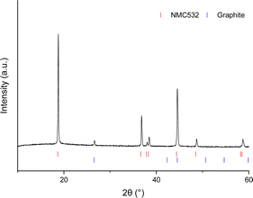 | ||
| Fig. 1 Powder XRD patterns of cathode material with layered NMC oxide and carbon phases given as red and blue ticks respectively (CuKα1/Kα2). In these electrodes graphitic phase is used as a carbon additive.32 | ||
| Lattice parameters | |
|---|---|
| a = 2.86868(4) Å | c = 14.2348(4) Å |
| Molar ratio | |||
|---|---|---|---|
| Ni | Mn | Co | Li![[thin space (1/6-em)]](https://www.rsc.org/images/entities/char_2009.gif) : :![[thin space (1/6-em)]](https://www.rsc.org/images/entities/char_2009.gif) M ratio where M = Mn, Ni and Co M ratio where M = Mn, Ni and Co |
| 0.48 | 0.28 | 0.24 | 1.04 |
Thermal treatment for delamination and binder removal
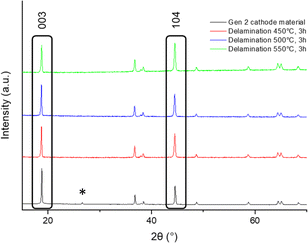
In the first instance a thermal treatment was used to decompose the binder and so allow delamination of the cathode material from the Al current collector, in order to recover both the cathode material and the current collector. In this step it is important that the cathode material and aluminium current collector are easily separated avoiding damage to either component, and so the temperature must be limited to lower temperatures (in this case temperatures ≤550 °C were examined). Air was chosen due to the lower cost when compared to O2, and furthermore work by Tanaka et al.33 also reports explosive combustion of PVDF at 500 °C in O2.The first thermal heat treatment was therefore carried out at temperatures between 350 and 550 °C for 12 h (ESI, Fig S2†) to identify the optimal temperature for delamination. The results showed that, at 350 °C, samples were not easily delaminated, while delamination was readily observed for temperatures between 450 and 550 °C. Further studies then investigated reducing the heating time to 3 h for the temperatures between 450 and 550 °C (Fig. 2). After the 3 h heat treatment, delamination of all samples was achieved, and all delaminated cathode materials appeared phase pure by XRD, with the observed removal of the small carbon (conducting additive) peak at ≈ 27° 2-theta. However, the data did show some small intensity variations in the peaks, with the most notable difference for the (003)/(104) peak intensity ratio at 2-theta ≈ 19° (003) and 45° (104) (Fig. 2). This peak ratio is commonly used to determine the degree of cation mixing in layered oxide cathode materials.34 Typically a ratio of >1.2 is considered to have negligible cation mixing.35–37 From the ratio of these peaks (Table 2) a similar level of Li/M site mixing was observed when delaminating at 450 °C and 500 °C, while at the higher temperature of 550 °C, there appears to be an increase in Li/M site mixing, which may relate to a small level of F incorporation from this heat treatment (PVDF has previously been used as a fluorinating reagent at low temperatures for mixed metal oxide compounds).38,39
| Reaction conditions | (003)/(104) peak ratio | Li/M site mixing | Lattice parameters/Å |
|---|---|---|---|
| Cathode material before treatment | 1.91 | 0.022(1) | a = 2.86868(4) c = 14.2348(4) |
| Delamination: 450 °C in air for 3 h | 1.29 | 0.061(2) | a = 2.87056(6) c = 14.2463(8) |
| Delamination: 500 °C in air for 3 h | 1.37 | 0.059(2) | a = 2.87085(6) c = 14.2462(7) |
| Delamination: 550 °C in air for 3 h | 0.97 | 0.086(2) | a = 2.87212 (7) c = 14.2510(8) |
In particular, the heating with PVDF may possibly lead to the presence of Li defects due a small amount of Li being removed as LiF.
In order to regenerate the cathode material, a second heat treatment in O2 was carried out to reduce site mixing and ensure complete removal of binder, other carbon-based by-products and any F contamination. Across a range of temperatures (first heat treatment 450–500 °C in air, second heat treatment 800–850 °C in O2) the XRD data (Fig. 3) show similar site mixing values, although for the sequence of heat treatments of 500 °C for 3 h (for delamination) and 825 °C for 3 h (for cathode regeneration), an improvement in the (003)/(104) peak ratio was observed (Table 3). Electrochemical testing (2.5–4.2 V range) in lithium half-cells was performed to evaluate the regenerated material. The electrochemical testing, however, showed that for all thermal treatments investigated, the discharge capacity was lower than reported in literature for NMC532, and there was a large difference between the first cycle charge–discharge capacities. Therefore, the results indicated that further optimisation work was required. Due to the improvement in (003)/(104) peak ratio, signifying the lowest quantity of cation mixing (Table 3), the cathode material heated at 500 °C for 3 h, 825 °C for 3 h in O2 was selected for further optimisation.
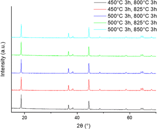 | ||
| Fig. 3 XRD patterns of cathode material after two heat treatments (delamination: 450–550 °C for 3 h, final heat treatment 800–850 °C for 3 h in O2). | ||
| Reaction conditions | (003)/(104) peak ratio | Li/M site mixing | Lattice parameters/Å | First cycle discharge capacity/mA h g |
|---|---|---|---|---|
| Delamination: 450 °C in air for 3 h | 1.27 | 0.061(2) | a = 2.87258(4) | 137(1) |
| Annealing: 800 °C in O2 for 3 h | c = 14.2513(5) | |||
| Delamination: 450 °C in air for 3 h | 1.28 | 0.053(2) | a = 2.87240(5) | 130(7) |
| Annealing: 825 °C in O2 for 3 h | c = 14.2508(6) | |||
| Delamination: 500 °C in air for 3 h | 1.32 | 0.056(1) | a = 2.87264(4) | 126(2) |
| Annealing: 800 °C in O2 for 3 h | c = 14.2517(4) | |||
| Delamination: 500 °C in air for 3 h | 1.42 | 0.054(2) | a = 2.87229(4) | 129(2) |
| Annealing: 825 °C in O2 for 3 h | c = 14.2499(5) | |||
| Delamination: 500 °C in air for 3 h | 1.25 | 0.059(2) | a = 2.87249(4) | 131(3) |
| Annealing: 850 °C in O2 for 3 h | c = 14.2520(5) |
Optimisation of performance through additional lithiation
After delamination, the ICP-OES data suggests a small Li deficiency (ESI, Table S3†) which could explain the lower discharge capacity on thermal regeneration (Table 3). Therefore, experiments were performed investigating the effect of adding additional Li after the delamination step to help relithiate the cathode. The wt% of LiOH·H2O amount was calculated using the mass of the sample after initial heat treatment of 500 °C 3 h in air. All cathode materials were heated using the same conditions (500 °C 3 h air, 825 °C 3 h O2) to investigate the effect of additional Li on the structural properties and electrochemical performance.Li addition of between 2.5 and 10 wt% LiOH·H2O were investigated. The results suggest an initial reduction in the Li/Ni site mixing with increasing LiOH·H2O which plateaus around 3 wt% Li (Fig. 4). Furthermore, with increasing LiOH·H2O, a decrease in the a/c lattice parameters is shown which suggests an increase in lithium content of the NMC material (Fig. 4).
 | ||
| Fig. 4 Data from Rietveld refinement: lattice parameters (a and c) and % Li/Ni site mixing of relithiated cathode materials. Estimated errors are included, but are smaller than the symbols. | ||
To investigate the effect of the thermal treatment on the morphology, SEM images were collected (Fig. 5). Before thermal treatment, SEM images indicate areas of PVDF present in the cathode material due to F being present in the EDX data (ESI, Fig S5†). After the initial 500 °C firing treatment there are some small areas of F still present on the recovered aluminium current collector (ESI, Fig S6†), although there are no significant morphology changes to the cathode material, and the Al current collector remains intact (ESI†). Furthermore after the higher temperature (825 °C 3 h O2) with added LiOH·H2O, the sample morphology is still maintained, and there is no evidence of any F left (ESI, Fig S7†). This highlights the non-destructive nature of this direct recycling method in terms of preserving the integrity of both the cathode material and Al current collector.
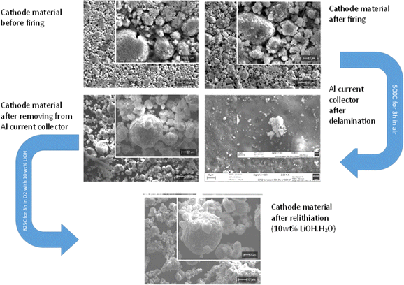 | ||
| Fig. 5 SEM images of cathode material before thermal treatment, and after delamination and relithiation. SEM images of aluminium foil after delamination step. | ||
Following on from the XRD and SEM characterisation, coin cells were prepared with the regenerated cathode materials to investigate the effect of adding additional Li on electrochemical performance (2.5–4.2 V range). A clear increase in electrochemical performance is observed with increasing Li content; this increase, begins to plateau at ≈147 mA h g−1 at 5% (Fig. 6). We additionally observe a reduction in the difference between the first cycle charge and discharge capacities with increasing Li (Fig. 6 and 7). Overall, the results show that the optimum conditions for the thermal regeneration are 500 °C for 3 h in air followed by 825 °C for 3 h in O2 with 10 wt% LiOH·H2O. This gives a material that has an improvement in Li/Ni site mixing leading to promising electrochemical performance in terms of both capacity and first cycle efficiency.
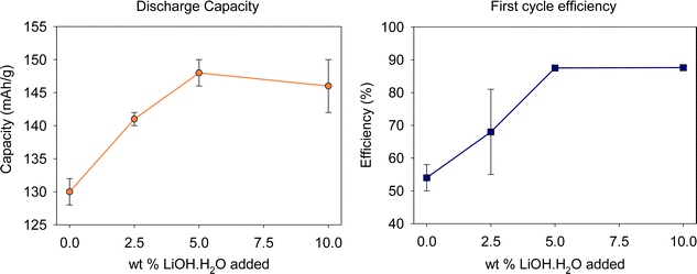 | ||
| Fig. 6 Electrochemical data (discharge capacity (upper voltage limit 4.2 V) and first cycle efficiency) of relithiated cathode materials. | ||
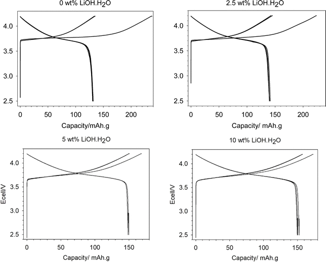 | ||
| Fig. 7 Electrochemical data (2.5–4.2 V range) for relithiated samples with added Li of 0 wt% (top left), 2.5 wt% (top right), 5 wt% (bottom left) and 10 wt% (bottom right). | ||
Further studies, using the same thermal regeneration procedure, investigated the effect of expanding the voltage window by increasing the upper cut-off voltage to 4.3 V. Coin cells were tested at 2.5–4.3 V with 3 cycles at 10 mA g−1 followed by 50 cycles at 40 mA g−1 to investigate the stability in this larger voltage window. The increase in the voltage window from 2.5–4.2 V to 2.5–4.3 V resulted in a significant improvement in discharge capacity (Fig. 8) with the first cycle discharge capacity increasing to 164(2) mA h g−1, compared to 146(4) mA h g−1 (2.5–4.2 V). This capacity is comparable to literature data for NMC532 materials illustrating the success of this direct recycling approach.40,41 The regenerated material also has good capacity retention over 50 cycles at 40 mA g−1.
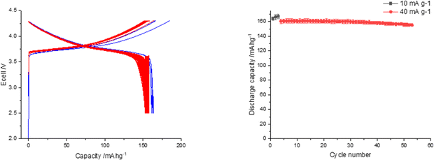 | ||
| Fig. 8 Electrochemical data for relithiated sample (500 °C for 3 h in air followed by 825 °C for 3 h in O2 with 10 wt% LiOH·H2O) tested between the voltage range 2.5 and 4.3 V. | ||
Significantly the direct recovery and regeneration of this NMC532 cathode only employs two short term (3 h) heating steps, which represents a significant potential cost saving compared to current industrial hydrometallurgical recycling. In the latter the cathode is dissolved (typically using an inorganic acid (such as H2SO4) and H2O2), and then multiple separation steps are employed to precipitate sequentially the individual metal salts. This would then be followed by the need to use these metal salts to remanufacture the cathode with both the desired composition and morphology, a process that takes significant time and energy.
Conclusions
In this paper we have highlighted a combined delamination and direct recycling approach for EV (NMC532) production scrap utilising simple short thermal treatments. An initial 500 °C (3 h in air) heat treatment leads to decomposition of the PVDF binder resulting in the delamination of the active material from the aluminium current collector. At this stage, the Al current collector is preserved, allowing this to then be potentially reprocessed and reused through traditional Al recycling schemes. The delaminated cathode material retains its initial morphology and following a direct recycling (re-lithiation) approach at higher temperature, results in a regeneration of NMC532 material with renewed capacity. Compared to current industry multistep pyrometallurgy or hydrometallurgy recycling methods, this direct recycling method highlights the potential for a more efficient and sustainable approach to Li-ion battery recycling.Data availability
All data associated with this paper are openly available from: https://doi.org/10.25500/edata.bham.00001138.Author contributions
E. C. Giles: conceptualization, investigation, formal analysis, visualization. A. Jarvis: investigation, formal analysis, visualization, writing – original draft, writing – review & editing. A. T. Sargent: investigation, formal analysis, visualization, writing – review & editing. P. A. Anderson: conceptualization, funding acquisition, supervision, writing – review & editing. P. K. Allan: conceptualization, funding acquisition, supervision, writing – review & editing. P. R. Slater: conceptualization, funding acquisition, supervision, writing – review & editing.Conflicts of interest
There are no conflicts to declare.Acknowledgements
Authors would like to thank the Faraday Institution's ReLiB, CATMAT and NEXTRODE projects for funding (grant numbers FIRG005, FIRG015, FIRG016, FIRG027 and FIRG057, FIRG063).Notes and references
- H. Government, Net Zero Strategy: Build Back Greener, https://assets.publishing.service.gov.uk/government/uploads/system/uploads/attachment_data/file/1033990/net-zero-strategy-beis.pdf, accessed 24 January 2024.
- U. S. D. of S. and the U. S. E. O. of the President, The long-term strategy of the United States: Pathways to Net-Zero Greenhouse Gas Emissions by 2050, https://www.whitehouse.gov/wp-content/uploads/2021/10/US-Long-Term-Strategy.pdf, accessed 24 January 2024.
- E. Commission and D.-G. for C. Action, Going climate-neutral by 2050 – A strategic long-term vision for a prosperous, modern, competitive and climate-neutral EU economy, https://op.europa.eu/en/publication-detail/-/publication/92f6d5bc-76bc-11e9-9f05-01aa75ed71a1, accessed 24 January 2024.
- G. E. Collis, Q. Dai, J. S. C. Loh, A. Lipson, L. Gaines, Y. Zhao and J. Spangenberger, Recycling, 2023, 8, 78–98 CrossRef.
- J. Harty, Six key trends in the battery recycling market, https://www.fastmarkets.com/insights/six-key-trends-battery-recycling-market/, accessed 24 January 2024.
- C. E. Storage, The good news about battery production scrap, https://circularenergystorage.com/articles/2022/6/16/the-good-news-about-battery-production-scrap, accessed 24 February 2024.
- L. Gaines, J. Zhang, X. He, J. Bouchard and H. E. Melin, Batteries, 2023, 9, 360–382 CrossRef CAS.
- G. Harper, R. Sommerville, E. Kendrick, L. Driscoll, P. Slater, R. Stolkin, A. Walton, P. Christensen, O. Heidrich, S. Lambert, A. Abbott, K. Ryder, L. Gaines and P. Anderson, Nature, 2019, 575, 75–86 CrossRef CAS.
- M. A. Rajaeifar, M. Raugei, B. Steubing, A. Hartwell, P. A. Anderson and O. Heidrich, J. Ind. Ecol., 2021, 25, 1560–1571 CrossRef CAS.
- R. Sommerville, P. Zhu, M. A. Rajaeifar, O. Heidrich, V. Goodship and E. Kendrick, Resour., Conserv. Recycl., 2021, 165, 105219–105229 CrossRef CAS.
- G. D. J. Harper, E. Kendrick, P. A. Anderson, W. Mrozik, P. Christensen, S. Lambert, D. Greenwood, P. K. Das, M. Ahmeid, Z. Milojevic, W. Du, D. J. L. Brett, P. R. Shearing, A. Rastegarpanah, R. Stolkin, R. Sommerville, A. Zorin, J. L. Durham, A. P. Abbott, D. Thompson, N. D. Browning, B. L. Mehdi, M. Bahri, F. Schanider-Tontini, D. Nicholls, C. Stallmeister, B. Friedrich, M. Sommerfeld, L. L. Driscoll, A. Jarvis, E. C. Giles, P. R. Slater, V. Echavarri-Bravo, G. Maddalena, L. E. Horsfall, L. Gaines, Q. Dai, S. J. Jethwa, A. L. Lipson, G. A. Leeke, T. Cowell, J. G. Farthing, G. Mariani, A. Smith, Z. Iqbal, R. Golmohammadzadeh, L. Sweeney, V. Goodship, Z. Li, J. Edge, L. Lander, V. T. Nguyen, R. J. R. Elliot, O. Heidrich, M. Slattery, D. Reed, J. Ahuja, A. Cavoski, R. Lee, E. Driscoll, J. Baker, P. Littlewood, I. Styles, S. Mahanty and F. Boons, JPhys Energy, 2023, 5, 21501 CrossRef.
- D. L. Thompson, J. M. Hartley, S. M. Lambert, M. Shiref, G. D. J. Harper, E. Kendrick, P. Anderson, K. S. Ryder, L. Gaines and A. P. Abbott, Green Chem., 2020, 22, 7585–7603 RSC.
- X.-T. Wang, Z.-Y. Gu, E. H. Ang, X.-X. Zhao, X.-L. Wu and Y. Liu, Interdiscip. Mater., 2022, 1, 417–433 CrossRef.
- J. Zhou, X. Zhou, W. Yu, Z. Shang and S. Xu, Electrochem. Energy Rev., 2024, 7, 13 CrossRef CAS.
- K. H. Chan, M. Malik and G. Azimi, Mater. Today Energy, 2023, 37, 101374–101387 CrossRef CAS.
- S. E. Sloop, J. E. Trevey and L. Gaines, ECS Trans., 2018, 85, 397–403 CrossRef CAS.
- A. T. Montoya, Z. Yang, E. U. Dahl, K. Z. Pupek, B. Polzin, A. Dunlop and J. T. Vaughey, ACS Sustain. Chem. Eng., 2022, 10, 13319–13324 CrossRef CAS.
- M. Du, K. Di Du, J. Z. Guo, Y. Liu, V. Aravindan, J. L. Yang, K. Y. Zhang, Z. Y. Gu, X. T. Wang and X. L. Wu, Rare Met., 2023, 42, 1603–1613 CrossRef CAS.
- S. Rosenberg, L. Kurz, S. Huster, S. Wehrstein, S. Kiemel, F. Schultmann, F. Reichert, R. Wörner and S. Glöser-Chahoud, Resour., Conserv. Recycl., 2023, 198, 107145–107156 CrossRef.
- L. Gaines, K. Richa and J. Spangenberger, MRS Energy Sustain., 2018, 5, 1–14 CrossRef.
- P. S. Grant, D. Greenwood, K. Pardikar, R. Smith and T. Entwistle, JPhys Energy, 2022, 4, 042006 CrossRef CAS.
- P. Zhu, P. R. Slater and E. Kendrick, Mater. Des., 2022, 223, 111208–111227 CrossRef CAS.
- C. Lei, I. Aldous, J. M. Hartley, D. L. Thompson, S. Scott, R. Hanson, P. A. Anderson, E. Kendrick, R. Sommerville, K. S. Ryder and A. P. Abbott, Green Chem., 2021, 23, 4710–4715 RSC.
- L. L. Driscoll, A. Jarvis, R. Madge, E. H. Driscoll, J. Price, R. Sommerville, F. Schnaider, M. Bahri, L. B. Mehdi, M. Miah, E. Kendrick, N. D. Browning, P. K. Allan, P. A. Anderson and P. R. Slater, Joule, 2024 DOI:10.1016/j.joule.2024.07.001.
- R. Madge, A. Jarvis, W. Lima da Silva, L. L. Driscoll, P. A. Anderson and P. R. Slater, RSC Sustainability, 2024, 2, 1408–1417 RSC.
- S. E. Sloop, L. Crandon, M. Allen, M. M. Lerner, H. Zhang, W. Sirisaksoontorn, L. Gaines, J. Kim and M. Lee, Sustainable Mater. Technol., 2019, 22, e00113 CrossRef CAS.
- T. Yingnakorn, J. Hartley, J. S. Terreblanche, C. Lei, W. M. Dose and A. P. Abbott, RSC Sustainability, 2023, 1, 2341–2349 RSC.
- Y. F. Meng, H. J. Liang, C. De Zhao, W. H. Li, Z. Y. Gu, M. X. Yu, B. Zhao, X. K. Hou and X. L. Wu, J. Energy Chem., 2022, 64, 166–171 CrossRef CAS.
- S. H. Zheng, X. T. Wang, Z. Y. Gu, H. Y. Lü, X. Y. Zhang, J. M. Cao, J. Z. Guo, X. T. Deng, Z. T. Wu, R. H. Zeng and X. L. Wu, J. Power Sources, 2023, 587, 233697 CrossRef CAS.
- A. T. Sargent, Z. Henderson, A. S. Walton, B. F. Spencer, L. Sweeney, W. R. Flavell, P. A. Anderson, E. Kendrick, P. R. Slater and P. K. Allan, J. Mater. Chem. A, 2023, 11, 9579–9596 RSC.
- P. Zhu, E. H. Driscoll, B. Dong, R. Sommerville, A. Zorin, P. R. Slater and E. Kendrick, Green Chem., 2022, 25, 3503–3514 RSC.
- Imerys, Graphite, https://www.imerys.com/minerals/graphite, accessed 30 April 2024.
- F. Tanaka, L. Gungaajav, O. Terakado, S. Kuzuhara and R. Kasuya, Thermochim. Acta, 2021, 702, 178977 CrossRef CAS.
- T. Ohzuku, A. Ueda and M. Nagayama, J. Electrochem. Soc., 1993, 140, 1862–1870 CrossRef CAS.
- Z. Liu, A. Yu and J. Y. Lee, J. Power Sources, 1999, 81–82, 416–419 CrossRef CAS.
- X. Luo, X. Wang, L. Liao, X. Wang, S. Gamboa and P. J. Sebastian, J. Power Sources, 2006, 161, 601–605 CrossRef CAS.
- F. Wang, Y. Zhang, J. Zou, W. Liu and Y. Chen, J. Alloys Compd., 2013, 558, 172–178 CrossRef CAS.
- P. R. Slater and J. Fluor, Chem, 2002, 117, 43–45 CAS.
- O. Clemens and P. R. Slater, Rev. Inorg. Chem., 2013, 33, 105–117 CAS.
- J. Kasnatscheew, S. Röser, M. Börner and M. Winter, ACS Appl. Energy Mater., 2019, 2, 7733–7737 CrossRef CAS.
- Targray, Targray NMC powder for battery manufacturers, https://www.targray.com/li-ion-battery/cathode-materials/nmc, accessed 30 April 2024.
Footnote |
| † Electronic supplementary information (ESI) available. See DOI: https://doi.org/10.1039/d4su00389f |
| This journal is © The Royal Society of Chemistry 2024 |

