Unveiling the magnetic ordering effect in La-doped Ti3C2O2 MXenes on electrocatalytic CO2 reduction
Koua Alain Jesus
Koua
 ab,
Jiahe
Peng
ab,
Peng
Zhang
ab,
Jiahe
Peng
ab,
Peng
Zhang
 c and
Neng
Li
 *ab
*ab
aState Key Laboratory of Silicate Materials for Architectures, School of Materials Science and Engineering, Wuhan University of Technology, Hubei 430070, China. E-mail: lineng@whut.edu.cn
bShenzhen Research Institute of Wuhan University of Technology, Shenzhen 518000, Guangdong, China
cState Centre for International Cooperation on Designer Low-Carbon & Environmental Materials (CDLCEM), School of Materials Science and Engineering, Zhengzhou University, Henan, Zhengzhou, 450001, P. R. China
First published on 4th December 2023
Abstract
In the pursuit of sustainable energy solutions, the carbon dioxide reduction reaction (CO2RR) holds immense promise for converting CO2 into valuable chemicals and fuels. In this view, the exploration of magnetic MXene catalysts is crucial for understanding their reactivity and performance in electrochemical reactions to improve the CO2 conversion process. Herein, two distinct magnetic configurations, ferromagnetic (FM) and antiferromagnetic (AFM), were considered for La-doped Ti3C2O2 (La-Ti3C2O2). Using density functional theory (DFT) calculations, the first principles simulation was carried out to evaluate the electronic properties, magnetic properties, and CO2RR potential of these configurations. Our findings reveal an enhancement in semiconductivity and surface reactivity of the La-Ti3C2O2 catalyst, resulting in improved electron transfer characteristics. This facilitates CO2 adsorption and decreases the formation energy barrier of intermediate species towards the CO2 hydrogenations. The La-Ti3C2O2 catalyst showed a better performance than the parent molecule Ti3C2O2, which suffers from an insufficiency of reactivity on its surface. Furthermore, the study demonstrates the AFM structure of La-Ti3C2O2 to be the soundest, which thereby displays a better efficiency than the FM structure. Considering our findings, during the current CO2 conversion process, the reaction pathway with a less energy consumption must be preferred over others.
1. Introduction
One of the primary roles of greenhouse gases in the atmosphere is to maintain the earth's temperature within a range of −21 °C to 14 °C, thereby preventing the earth from turning into a frigid planet.1 However, the current rapid surge in greenhouse gases resulting from the excessive utilization of fossil fuels is leading to global warming.2,3 With its status as one of the most prevalent greenhouse gases, CO2 at high concentrations in the atmosphere also pose a serious threat to human health.4–6 Consequently, the conversion of CO2 into less problematic and beneficial compounds is both obligatory and urgently needed.7–9 Numerous reports confirm that CO2 could be significantly mitigated through substantial advancements in electrocatalytic reactions.10–13 Fan Lei et al. succeeded in converting CO2 into formic acid (HCOOH) of a high purity and concentration by an electrocatalytic technique.14 Carbon monoxide (CO), formaldehyde (CH2O), methanol (CH3OH), and methane (CH4) may also be formed during the electrocatalytic CO2 reduction process.15–18 However, the effectiveness of CO2 reduction through electrocatalysis hinges on the presence of suitable and robust catalysts. While metal catalysts, such as Ru,19–22 Ir,23,24 Au,25 Ag,26,27 Pt,28 Cu,29,30 and TiO2 (ref. 31 and 32) showed promise in electrocatalysis, they have fallen short of both CO2 capture and hydrogenation processes despite diligent efforts. The introduction of graphene catalyst provided a significant boost,33 but further endeavors are necessary as the efficiency of CO2 reduction has yet to reach a milestone worth celebrating. With the new 2D MXene materials that have properties similar to graphene and also a large reactive surface area,34 metallic semiconductivity35,36 and hydrophobicity,37 the electrocatalytic reaction is experiencing a better progress.27,28,38–40MXenes are derivatives from layer compounds of formula Mn+1AXn called MAX phase compounds, where M is a transition metal, A is mainly an element of group IIIA or IVA, X is carbon or nitrogen, and n = 1, 2, or 3.41 Mxenes are obtained by etching layer A of MAX, which results in the Mxene general formula of Mn+1Xn. To achieve this, MAX is placed in an etching agent (HF, NH4HF2, ZnCl, and Ti4N3) for an appropriate time and then washed quite a few times with deionized water.42–50 Spectroscopic studies have revealed that the synthesis of Mxenes typically results in the formation of functional groups Tx (Tx = O, OH, and F) on their surfaces.45,51–57 These atom-terminated functional groups are very active43,46,58 and can contribute to the unique properties of MXenes that found applications in several areas such as energy storage,59–62 catalysis,63–66 electronics,67–69 water purification,70,71 thermoelectricity72,73 and so on. Among the atoms-terminated, O seems to be the most stable as others tend to undergo conversion into O under high temperatures.46,74 The oxygen on the surface of MXenes is an activated site for diverse reactions.75,76 Studies showed that heteroatom doped carbon-based catalysts have fascinating performances such as low applied voltage,77 high Faraday efficiency78,79 and long cycle life,80 and Anmin Liu et al. demonstrated that nitrogen-doped graphene shows high performance in the CO2RR.33 The spintronic field that studies the behaviors of electron charge and spin initiated the idea of investigating the magnetic effect of catalysts in catalysis. Neng Li et al. demonstrated that Fe and Ni used together in high spin and low spin, respectively, increase the catalyst performance for nitrogen reduction.81 The effect of spin in MXene catalysts on electrocatalytic CO2RR is, therefore, timely to be explored for CO2 utilization. According to the first-principles calculations, most of the MXenes are nonmagnetic, though some magnetic MXenes have been synthesized, such as V2C(OH)2, V2CF2, Cr2C(OH)2, and Cr2CF2, which are AFM.82 To find more magnetic MXenes, a new variety with a double transition metal of MnM'Xn was synthesized. Jianhui Yang et al. investigated the magnetic effect of double transition metal MXenes and found that the compounds Cr2VC2Tx are FM.82
Distinguished as benchmark MXenes, Ti3C2Tx stand out as the most readily synthesized variant, making them abundant and cost-effective for a wide range of applications. They boast impressive performance in electrochemistry, energy storage and gas sensor applications.83–85 However, their efficacy in CO2RR necessitates improved surface reactivity to effectively respond to spontaneous CO2 capture and hydrogenation reactions.86 Additionally, they exhibit minimal magnetic properties and do not fall into the coveted magnetic material category. Based on the findings of Iqbal Mehroz et al., upon lanthanum (La3+) doping into the Ti3C2Tx system, they display an improvement in electronic properties and undergo a transformation into magnetic materials, capable of displaying both FM and AFM configurations.87 Considering the boosted electronic and magnetic properties of La-Ti3C2Tx, and the presence of stable O-terminated functional groups, La-Ti3C2O2 is adopted as the catalyst material for conducting this simulation study on CO2RR. The objective is to master the challenging processes of spontaneous CO2 adsorption and hydrogenations, leading to the generation of valuable compounds and hydrocarbons. In this regard, we first assess the CO2 reduction performance using the magnetic La-Ti3C2O2 in comparison to its nonmagnetic counterpart Ti3C2O2. Subsequently, we conduct an efficiency comparison study between the FM and AFM structures of La-Ti3C2O2. Identifying an optimal pathway is crucial for enhancing the efficiency of electrocatalytic CO2RR, as certain pathways may offer energy savings compared to others. Hence, we investigate the probable routes taken by the reduction reactions, aiming to select the pathway characterized by lower energy consumption for the CO2 reduction process.
2. Modeling and simulation methods
Extensive studies conducted on Ti3C2 by Shein et al. revealed an FM alignment in the top Ti1 atom sheet that antiferromagnetically paired with the alignment in the bottom Ti1 sheet, while the internal Ti2 atom sheet was nonmagnetic. The ground state of Ti3C2 is, therefore, AFM and the atomic magnetic moment is 0.74μB per Ti atom.88 The O-functional group attached to the surface of Ti3C2 creates a weak FM effect87 and in this work, we consider Ti3C2O2 as a nonmagnetic material (Fig. 1a). The doping of Ti3C2O2 with La atoms at the Ti sites engenders disorder in electron distribution since La3+ is larger than Ti4+. This increases the saturation magnetization and enhances the magnetic effect of La-Ti3C2O2.87 Using the first principles calculations resulting from the DFT implemented in Materials Studio Castep, we perform this simulation study with two La atoms in a Ti3C2O2 system using a 3 × 3 × 1 supercell model, as shown in Fig. 1b. Note that La-Ti3C2O2 is magnetic and either a FM or AFM structure could be observed via the adsorbed La atoms, as shown in Fig. 1c and d. The calculated ground state energy showed stable AFM and FM structures with a difference in energy of 4.4 meV. The modelling vacuum thickness was about 15 Å following the z-direction, the cut-off energy was set to 450 eV, and the k-point was set to 3 × 3 × 1. The Perdew–Burke–Ernzerhof (PBE) functional was used regardless of the exchange and correlation energy. The Gibbs free energy of reaction (ΔG) was calculated using the formulae below:| ΔG = ΔEDFT + ΔZPE − TΔS | (1) |
 | (2) |
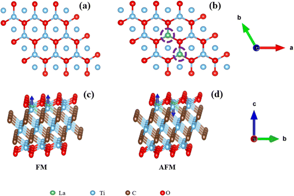 | ||
| Fig. 1 The view of Ti3C2O2 (a) and La-Ti3C2O2 (b) and the corresponding FM (c) and AFM (d) structures of La-Ti3C2O2. | ||
E DFT (MXene…S) = total energy of the MXene and adsorbed species.
E DFT (MXene…S–H) = total energy of the MXene and adsorbed species binding with H.
In particular, the binding energy ΔEDFT for CO2 and H* is expressed as follows:
| ΔEDFT (CO2) = EDFT (MXene….O2) − EDFT (MXene) − EDFT (CO2) | (3) |
 | (4) |
3. Electronic properties of materials
3.1 Contribution of La atoms in the Ti3C2O2 system
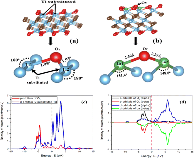
The geometry optimization of La-Ti3C2O2 in Fig. 2a and b confirms that the doping of Ti3C2O2 with the two La atoms engenders disturbance and defect in electron distribution. Fig. 2a represents the structure of Ti3C2O2 where we can see a perfect distribution of all the atoms. The two Ti atoms to be substituted (Ti1 and Ti2) form right angles with the Ti closers, and the oxygen atoms at the surface are well distributed. The presence of La1 and La2 at Ti1 and Ti2 sites disrupts the distribution of the atoms in the material. La1 and La2 endure displacement and move above from their initial positions, as shown in Fig. 2b. The surface oxygen atoms of the La-Ti3C2O2 material undergo disorganization, and the oxygen (Ov) on top, center and closer to La1 and La2 could serve as an activated site for the adsorption of the CO2.La-Ti3C2O2 crystallized in the hexagonal structure system,87 and the density of states (DOS) diagrams in Fig. 2c and d support the idea of an overlap between the d-orbitals of La atoms and the p-orbital of Ov around the Fermi level, while no overlap phenomena are observed between Ov and the two-substituted Ti in Ti3C2O2. This is because the contribution of La atoms has more impact on the material surface, which thereby displays evidence that Ti3C2O2 shows an enhancement in electronic properties when it is doped with La atoms. Additionally, the peak of Ov located around −2.6 eV in Fig. 2d is closer to the Fermi level compared to the peak around −4.5 eV observed in Fig. 2c. This translates that Ov is more activated in La-Ti3C2O2, and could facilitate the CO2 binding process.
3.2 Electronic and magnetic properties of the La-Ti3C2O2 material
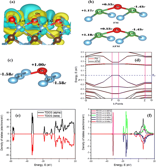
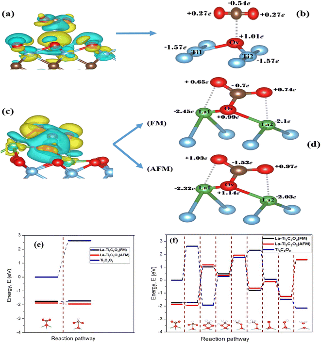
The electron density difference of La-Ti3C2O2 (both FM and AFM) in Fig. 3a is set considering the yellow color as electron density accumulation and the blue color as electron density loss. It shows that electron density is enriched around Ov and La1 at the edge, while the electron density is depleted around the inner La2. This is confirmed by the Bader charge analysis in Fig. 3b, which clearly depicts the negative charge on La2, indicating that La2 has transferred electrons to the surface oxygen atoms (especially Ov). The electron enrichment on Ov and La1 is harnessed to efficiently capture and hydrogenate CO2. On the other hand, this electron enrichment is a key aspect of designing efficient catalysts for CO2RR and achieving the desired product selectivity. Fig. 3c reveals through Bader charge analysis that in Ti3C2O2, Ti1 and Ti2 do enhance the electron density around Ov. Yet, their contributions may not be sufficient to induce the spontaneous capture and hydrogenation of CO2, especially when compared with the La-Ti3C2O2 case. In the La-Ti3C2O2 configuration, both La1 and Ov are capable of donating electrons to CO2, which appears to be a more conducive environment for these reactions. The band structure study of La-Ti3C2O2 in Fig. 3d provides 0.227 eV and 0.220 eV as the band gaps of FM and AFM structures, respectively. La-Ti3C2O2 exhibits a short distance between the valence band and the conduction band, indicating its strong semiconductor characteristics in both FM and AFM forms.Fig. 3e and f provide indications about the density of states of spin-up (alpha) and spin-down (beta) in La-Ti3C2O2. Fig. 3e is the total density of states and Fig. 3f is the partial density of states of La atoms. It can be seen that the peaks of the spin-up and spin-down have the same appearances and intensities in both figures. This is because the electronic structure of La-Ti3C2O2 allows electrons with both spin-up and spin-down orientations to occupy the same energy levels or states with equal probability. In that case, the spin alignment that corresponds to this material is AFM. This supports the slight difference in ground state energy and band gap of La-Ti3C2O2 (AFM), which could heighten the efficiency of the catalyst in the electrocatalytic CO2RR.
4. Results and discussion
4.1 Electrocatalytic CO2RR process
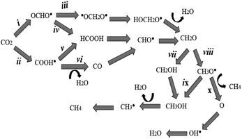
Fig. 2 and 3 illustrate La-Ti3C2O2 as a promising candidate for CO2 capture and subsequent hydrogenation reactions. Depending on the number of H+/e− pairs supplied by the catalyst, we obtain different products according to the considered reaction pathways. The CO2 reduction initiates with a physisorption step, where CO2 is adsorbed onto the activated catalyst material without altering its molecular structure. This is followed by a chemisorption reaction during which the CO2 structure is altered, and the catalyst donates the first H+/e− pair to CO2. The resulting species can be either OCHO˙ (i) or COOH˙ (ii). In path (ii) the second hydrogenation results in the formation of HCOOH (v), or CO (vi) is obtained after the desorption of H2O. Meanwhile, the attachment of the second proton on OCHO˙ (in i case) offers two possible outcomes. (iii) The proton can be placed on the carbon (˙OCH2O˙) or (iv) the proton binds the oxygen (HCOOH). In all the previously considered pathways, formaldehyde is obtained at the fourth hydrogenation. Another proton approaches CH2O and the binding process is either CH2OH (vii) or CH3O˙ (viii). The hydrogenation of CH3O˙ (stable) occurs following two possibilities: (ix) hydrogenation with the proton binding the oxygen (CH3OH) or (x) the proton approaches and binds the carbon of CH3O˙ followed by methane (CH4) release and O remains on the catalyst. From (ix), the hydrogenation of methanol leads to the formation of CH3˙ and H2O. The radical CH3˙, combined with H+/e−, turns to CH4. In all the cases, the catalyst material is regenerated after the desorption of CH4 or H2O, as shown in Scheme 1.4.2 Performance of the magnetic La-Ti3C2O2 MXene in CO2RR
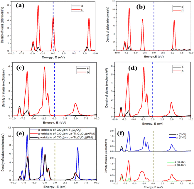
After selecting the carbon site of CO2 for the physisorption process, a chemical reaction takes place thereafter with this time deformation of CO2. The calculated chemisorption energies of −1.75 eV and −1.87 eV for the FM and AFM configurations, respectively, describe the feasibility of the binding process and confirm that La-Ti3C2O2 is active to accomplish the CO2 capture reaction. Fig. 5a is the density of states of the free CO2 molecule, where we can see a peak on the Fermi level. This peak suggests that there is a high density of electronic states related to the molecular orbitals, which may be associated with the π and σ bonding of CO2. This peak is specific to the electronic structure and potential reactivity of CO2 but does not imply metallic conductivity, as seen in solid materials. Fig. 5b–d show a deformation in the adsorbed CO2 structure, and confirm the chemical reactions that occurred between CO2 and the materials. The ability of CO2 to react with the materials depends on the involved material. In Fig. 5e we can see that the peak (−1.55 eV) of p-orbitals of CO2 adsorbed onto the AFM and FM configurations of La-Ti3C2O2 is closer to the Fermi level than the peak (−3.05 eV) of CO2 adsorbed onto Ti3C2O2, which is 2 times as far away from the Fermi level. As a result, CO2 becomes more activated, and its reactivity with La-Ti3C2O2 is significantly enhanced. Fig. 5f shows the curves of the density of states of the bond C–O (in CO2) and the bond C–Ov (bond between Ov and C of CO2) in both FM and AFM structures of La-Ti3C2O2. Overall, the appearance and specific peaks of C–Ov match with the normal bond of C–O. The large peaks within a range of −5 to −1.05 eV of C–Ov could be explained by a significant concentration of available energy states for electrons provided by the catalyst. This approves that the bond C–Ov is truly a normal C–O bond, and confirms that CO2 is effectively linked onto La-Ti3C2O2 through Ov. In addition, the substantial concentration of electrons observed through this large peak could act as a facilitator to initiate the hydrogenation processes.
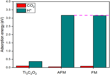
This first hydrogenation is promoted through the low energy barrier of the reaction between the catalyst and CO2. The calculated Gibbs free energy to obtain OCHO˙ gives −1.72 eV and −1.94 eV for La-Ti3C2O2 (FM) and La-Ti3C2O2 (AFM), respectively, against the 2.62 eV for Ti3C2O2 evinced in Fig. 6e. It can, therefore, be seen that the needed energy for OCHO˙ formation becomes lower when using the La-Ti3C2O2 catalyst, while the reaction with Ti3C2O2 struggles to trigger due to the high reaction energy barrier. This corroborates that the incorporation of La atoms into the Ti3C2O2 structure represents a groundbreaking solution to the difficult hurdle associated with the initial hydrogenation of CO2. The presence of La enhances the material surface and then facilitates the electron supply from the catalyst to the substrate for the reduction process. Given that La3+ (0.106 nm) has a larger atomic size than Ti4+ (0.058 nm), La-Ti3C2O2 boasts a greater surface area, which translates into enhanced adsorption and hydrogenation efficiency. Additionally, the magnetic effect of La-Ti3C2O2 introduces additional electrostatic interactions with CO2, enhancing electron transfer characteristics. The spins stimulate a targeted orientation of the La-Ti3C2O2 catalyst electrons towards the substrate. Magnetic catalysts are desirable in improving the material's capability to effectively react with the substrate during this CO2RR. The La-Ti3C2O2 catalyst, therefore, promotes electrocatalytic CO2RR to produce valuable compounds and hydrocarbons, and shows higher efficiency than Ti3C2O2 (Fig. 6f). Furthermore, we observe that the AFM configuration displays a lower energy barrier of reaction than the FM one and could tame better the difficult action of obtaining OCHO˙. Since the electron spins of the magnetic La-Ti3C2O2 are not polarized in one direction, the AFM alignment is the proper and steadiest state of La-Ti3C2O2. This explains the good proficiency of La-Ti3C2O2 (AFM) in this electrocatalytic CO2RR investigation.
4.3 Favorable pathway of the reduction process
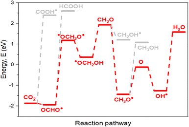
The pathways outlined in Scheme 1 represent potential electrocatalytic directions for CO2RR during the process. Nevertheless, certain pathways exhibit thermodynamic preference, making them more favorable. Species characterized by lower energy barriers of formation (with all three materials for accurate evaluation) are stable and preferentially obtained (Table 1). The first hydrogenation, where a proton binds to the carbon of CO2 (OCHO˙), exhibits a significantly lower energy barrier and stronger stability compared to proton placement on the oxygen atom (COOH˙). Consequently, OCHO˙ demonstrates a higher likelihood of formation, making pathway (i) the thermodynamically preferred route. In the second hydrogenation along the path (i), there are two potential outcomes, ˙OCH2O˙ (iii) or HCOOH (iv). Energy calculations indicate that the formation of ˙OCH2O˙ is more favorable, as it has a lower energy barrier. Therefore, ˙OCH2O˙ is selected to proceed with subsequent reactions, ultimately leading to the production of formaldehyde during the fourth hydrogenation. For the fifth hydrogenation, the likely products are CH2OH (vii) and CH3O˙ (viii). The radical CH3O˙ displays a lower energy barrier of formation than CH2OH, providing further support for the preference of path (viii). Regarding the sixth hydrogenation, it is evident that continuing the reaction with O (lower energy of formation) is more advantageous than with CH3OH. The path (x) is considered due to its lower energy consumption. Considering the above results, the favorable possibility in this simulation to well approach the CO2RR is to follow (i), (iii), (viii) and (x) directions. The optimal pathway direction for conducting this electrocatalytic CO2RR with the enhanced catalyst material La-Ti3C2O2 (AFM) is therefore proposed in Fig. 8.| Compounds | La-Ti3C2O2 (FM) | La-Ti3C2O2 (AFM) | Ti3C2O2 |
|---|---|---|---|
| CO2 | −1.75 | −1.87 | −0.005 |
| OCHO˙ | −1.72 | −1.94 | 2.62 |
| COOH˙ | 2.39 | 2.39 | 0.37 |
| ˙OCH2O˙ | 1.01 | 1.18 | −1.92 |
| HCOOH | 2.42 | 2.60 | −1.39 |
| CO | −1.18 | −1.18 | 0.40 |
| HOCH2O˙ | 0.48 | 0.36 | 0.30 |
| CHO˙ | 0.74 | 0.71 | −0.04 |
| CH2O | 1.92 | 1.90 | 1.75 |
| CH3O˙ | −0.78 | −0.62 | 2.30 |
| CH2OH | 1.03 | 1.20 | −0.46 |
| O | −0.10 | −0.11 | 0.06 |
| CH3OH | 1.14 | 1.08 | −1.46 |
| OH˙ | −1.30 | −1.26 | −1.47 |
| H2O | 1.60 | 1.58 | −2.15 |
| CH3˙ | 2.04 | 2.12 | 2.44 |
| CH4 | −0.78 | −0.80 | −1.77 |
5. Conclusion
First principles calculations using DFT were employed to assess the effectiveness of electrocatalytic CO2RR using MXene catalysts. Simulations carried out with La-Ti3C2O2 affirmed the materials' capability for spontaneous CO2 capture and hydrogenation reactions. La-Ti3C2O2 exhibits an enhancement in electronic properties and surface reactivity, which contributes to reducing the formation energy barrier of intermediate species during electrocatalytic CO2RR. The magnetic effect of La-Ti3C2O2 enhances the material's ability to react with the adsorbed substrate and assist the CO2RR, resulting in the production of hydrocarbons and other valuable compounds. This advancement addresses both ecological and energy-related concerns. Furthermore, the investigations have unveiled that the tangible magnetic structure of La-Ti3C2O2 is AFM and thereby exhibits superior performance than the FM configuration. Additionally, it is essential to carry out the electrocatalytic CO2 reduction while considering the direction that consumes less energy, as this aspect is of utmost usefulness for efficiency.Conflicts of interest
There are no conflicts to declare.Acknowledgements
This work is supported by the Natural Science Fund for Distinguished Young Scholars of Hubei Province (No. 2020CFA087); Guangdong Basic and Applied Basic Research Foundation (No. 2022A1515011303), the Basic Research Program of Shenzhen (No. JCYJ20190809120015163), the Central Government Guides Local Science and Technology Development Funds to Freely Explore Basic Research Projects (2021Szvup106), and the Fundamental Research Funds for the Central Universities.References
- T. R. Anderson, E. Hawkins and P. D. Jones, Endeavour, 2016, 40(3), 178–187 CrossRef PubMed.
- M. Meinshausen and W. Hare, et al. , Nature, 2009, 458, 1158–1162 CrossRef CAS PubMed.
- W. Peng and W. Zhou, et al. , Sci. Total Environ., 2018, 619, 1163–1169 Search PubMed.
- C. Duarte, J. Łukasz and J. Mariusz, Front. Public Health, 2020, 8, 543322 CrossRef.
- A. Jacobson Tyler, J. S. Kler, T. Hernke Michael, K. Braun Rudolf, C. Meyer Keith and W. E. Funk, Nat Sustain., 2019, 2, 691–701 CrossRef.
- N. Hudda and S. A. Fruin, Sci. Total Environ., 2018, 610, 1448–1456 CrossRef PubMed.
- U. Terranova, F. Viñes, N. H. De Leeuw and F. Illas, J. Mater. Chem. A, 2020, 8, 9392–9398 RSC.
- E. Trenberth Kevin, T. Fasullo John and K. Jeffrey, Bull. Am. Meteorol. Soc., 2009, 90(3), 311–323 CrossRef.
- R. B. Jackson, P. Friedlingstein, R. M. Andrew, J. G. Canadell, C. Le Quéré and G. P. Peters, Environ. Res. Lett., 2019, 14, 121001 CrossRef CAS.
- Y. Wang, B. Xia, H. Qin, F. Wang, Y. Li, X. Li, S. Kang, Y. Zuo and L. Cui, ACS Appl. Mater. Interfaces, 2016, 8(27), 17212–17219 CrossRef CAS PubMed.
- X. Li, J. Yu, J. Mietek and X. Chen, Chem. Rev., 2019, 119(6), 3962–4179 CrossRef CAS PubMed.
- C. Hiragond, H. Kim, J. Lee, S. Sorcar, C. Erkey and S. I. In, Catalysts, 2020, 10(1), 98 CrossRef CAS.
- N. Li, X. Chen, W.-J. Ong, D. R. MacFarlane, X. Zhao, A. K. Cheetham and C. Sun, ACS Nano, 2017, 11(11), 10825–10833 CrossRef CAS PubMed.
- L. Fan, C. Xia, P. Zhu, Y. Lu and H. Wang, Nat. Commun., 2020, 11(1), 3633 CrossRef CAS PubMed.
- J. Gu, C.-S. Hsu, L. Bai, H. M. Chen and X. Hu, Science, 2019, 364(6445), 1091–1094 CrossRef CAS.
- K. Nakata, T. Ozaki, T. Chiaki, A. Fujishima and E. Yasuaki, Angew. Chem., Int. Ed., 2014, 53(3), 871–874 CrossRef CAS PubMed.
- F. Sha, Z. Han, S. Tang, J. Wang and C. Li, ChemSusChem, 2020, 13(23), 6160–6181 CrossRef CAS PubMed.
- H. Arandiyan, K. Kani, Y. Wang, B. Jiang, J. Kim, M. Yoshino, M. Rezaei, A. E. Rowan, H. Dai and Y. Yamauchi, ACS Appl. Mater. Interfaces, 2018, 10(30), 24963–24968 CrossRef CAS PubMed.
- S. Wang, E. T. Schrunk, H. Mahajan and R. J. Farrauto, Catalysts, 2017, 7(12), 88_ CrossRef.
- B. Arghya, H. H. Anton and V. Tejs, J. Phys. Chem. C, 2017, 121(34), 18333–18343 CrossRef.
- K. Mohammadreza, A. Hansen Heine, R. Jan and K. Nørskov Jens, ACS Catal., 2015, 5(7), 4075–4081 CrossRef.
- A. Jaleel, S. H. Kim, P. Natarajan, G. H. Gunasekar, K. Park, S. Yoon and K. D. Jung, J. CO2 Util., 2020, 35, 245–255 CrossRef CAS.
- H. Zhao, H. Zhu, Y. Feng, Q. Zhao, B. Suo and W. Zou, et al. , ChemElectroChem, 2020, 7(24), 5036–5043 CrossRef CAS.
- K. Tang, Z. Wang, W. Zou, H. Guo, Y. Wu, Y. Pu, Q. Tong, H. Wan, X. Gu, L. Dong, J. Rong and Y. W. Chen, ACS Appl. Mater. Interfaces, 2021, 13(5), 6219–6228 CrossRef CAS PubMed.
- S. Zhao, Z. Tang, S. Guo, M. Han, C. Zhu, Y. Zhou, B. Liang, J. Gao, H. Huang, Y. Li, Y. Liu and Z. Kang, ACS Catal., 2017, 8(1), 188–197 CrossRef.
- J. Rosen, G. S. Hutchings, Q. Lu, S. Rivera, Y. Zhou, D. G. Vlachos and F. Jiao, ACS Catal., 2015, 5(7), 4293–4299 CrossRef CAS.
- Z. Zhang, H. Li, G. Zou, C. Fernandez, B. Liu, Q. Zhang and Q. Peng, ACS Sustain. Chem. Eng., 2016, 4(12), 6763–6771 CrossRef CAS.
- X. Xie, S. Chen, W. Ding, Y. Nie and Z. Wei, Chem. Commun., 2013, 49(86), 10112_ RSC.
- G. Yin, M. Nishikawa, Y. Nosaka, N. Srinivasan, D. Atarashi, E. Sakai and M. Miyauchi, ACS Nano, 2015, 9(2), 2111–2119 CrossRef CAS PubMed.
- Z. Changjun, Nat. Energy, 2016, 1(8), 16124 CrossRef.
- T. P. Nguyen, D. Nguyen, V. H. Nguyen, T. H. Le, D. N. Vo, Q. T. Trinh, S. R. Bae, S. Y. Chae, S. Y. Kim and Q. V. Le, Nanomaterials, 2020, 10(2), 337 CrossRef CAS PubMed.
- M. Tasbihi, K. Kamila, I. Troppová, M. Edelmannová, M. Reli, L. Čapek and R. Schomäcker, Environ. Sci. Pollut. Res. Int., 2018, 25(35), 34903–34911 CrossRef CAS PubMed.
- A. Liu, W. Guan, K. Wu, X. Ren, L. Gao and T. Ma, Appl. Surf. Sci., 2021, 540, 148319_ CrossRef CAS.
- P. A. Maughan, L. Bouscarrat, V. R. Seymour, S. Shao and S. J. Haigh, et al. , Nanoscale Adv., 2021, 3(11), 3145–3158 RSC.
- B. Lyu, M. Kim, H. Jing, J. Kang, C. Qian, S. Lee and J. H. Cho, ACS Nano, 2019, 13(10), 11392–11400 CrossRef CAS PubMed.
- B. Zazoum, A. Bachri and J. Nayfeh, Materials, 2021, 14(21), 6603 CrossRef CAS PubMed.
- J. Liu, H.-B. Zhang, R. Sun, Y. Liu, Z. Liu, A. Zhou and Z.-Z. Yu, Adv. Mater., 2017, 29(38), 1702367 CrossRef PubMed.
- J. Zhu, H. Enna, G. Zhao, Y. Zhou, D. Huang and G. Yue, et al. , Coord. Chem. Rev., 2017, 352, 306–327 CrossRef CAS.
- G. Gao, A. P. O'Mullane and A. Du, ACS Catal., 2016, 7(1), 494–500 CrossRef.
- C. Ling, L. Shi, Y. Ouyang and J. Wang, Chem. Mater., 2016, 28, 9026–9032 CrossRef CAS.
- R. M. Ronchi, J. T. Arantes and S. F. Santos, Ceram. Int., 2019, 45(15), 18167–18188 CrossRef CAS.
- M. Naguib, V. N. Mochalin, M. W. Barsoum and Y. Gogotsi, Adv. Mater., 2013, 26(7), 992–1005 CrossRef PubMed.
- M. Naguib, O. Mashtalir, J. Carle, V. Presser, J. Lu, L. Hultman and M. W. Barsoum, ACS Nano, 2012, 6(2), 1322–1331 CrossRef CAS PubMed.
- B. Anasori, Y. Xie, M. Beidaghi, J. Lu, B. C. Hosler, L. Hultman, P. R. Kent, Y. Gogotsi and M. W. Barsoum, ACS Nano, 2015, 9(10), 9507–9516 CrossRef CAS PubMed.
- M. Naguib, M. Kurtoglu, V. Presser, J. Lu, J. Niu, M. Heon and M. W. Barsoum, Adv. Mater., 2011, 23(37), 4248–4253 CrossRef CAS PubMed.
- Y. Xie, M. Naguib, V. N. Mochalin, M. W. Barsoum and Y. Gogotsi, et al. , J. Am. Chem. Soc., 2014, 136(17), 6385–6394 CrossRef CAS PubMed.
- F. Liu, J. Zhou, S. Wang, B. Wang, C. Shen, L. Wang, Q. Hu, Q. Huang and A. Zhou, J. Electrochem. Soc., 2017, 164, A709 CrossRef CAS.
- J. Halim, M. R. Lukatskaya, K. M. Cook, J. Lu, C. R. Smith, L. A. Näslund, S. J. May, L. Hultman, Y. Gogotsi, P. Eklund and M. W. Barsoum, Chem. Mater., 2014, 26(7), 2374–2381 CrossRef CAS PubMed.
- M. Li, J. Lu, K. Luo, Y. Li, K. Chang and K. Chen, et al. , J. Am. Chem. Soc., 2019, 141(11), 4730–4737 CrossRef CAS.
- U. Patrick and A. Babak, et al. , Nanoscale, 2016, 8(22), 11385–11391 RSC.
- M. Khazaei, M. Arai, T. Sasaki, C.-Y. Chung, N. S. Venkataramanan, M. Estili and Y. Kawazoe, Adv. Funct. Mater., 2012, 23(17), 2185–2192 CrossRef.
- I. R. Shein and A. L. Ivanovskii, Micro Nano Lett., 2013, 8(2), 59–62 CrossRef CAS.
- P. Paul, P. Chakraborty, T. Das, D. Nafday and T. Saha-Dasgupta, Phys. Rev. B, 2017, 96(7), 079903_ CrossRef.
- G. R. Berdiyorov, Europhys. Lett., 2015, 111(6), 67002 CrossRef.
- O. Mashtalir, M. Naguib and V. Mochalin, et al. , Nat. Commun., 2013, 4, 1716 CrossRef PubMed.
- J. H. Kristopher, B. Matthieu, M. Naguib, W. Barsoum Michel and R. Goward Gillian, J. Phys. Chem. C, 2015, 119(24), 13713–13720 CrossRef.
- H. Joseph, M. K. Cook, M. Naguib, P. Eklund, G. Yury, J. Rosen and W. Barsoum Michel, Appl. Surf. Sci., 2016, 362, 406–417 CrossRef.
- J.-H. YANG, S.-Z. Zhang, J.-L. JI and S.-H. Wei, Acta Phys.-Chim. Sin., 2015, 31(2), 369–376 CrossRef CAS.
- M. Ghidiu, R. Lukatskaya Maria, M.-Q. Zhao, Y. Gogotsi and M. W. Barsoum, Nature, 2014, 516, 78–81 CrossRef CAS PubMed.
- Q. Hu, H. Wang, Q. Wu, X. Ye, A. Zhou and D. Sun, et al. , Int. J. Hydrogen Energy, 2014, 39(20), 10606–10612 CrossRef CAS.
- C. E. Ren, M.-Q. Zhao, M. Taron, H. Joseph, B. Muhammad, K. Sankalp, A. Babak, M. W. Barsoum and G. Yury, ChemElectroChem, 2016, 3(5), 689–693 CrossRef CAS.
- Z. Bao, C. Lu, X. Cao, P. Zhang, L. Yang, H. Zhang, D. Sha, W. He, W. Zhang, L. Pan and Z. Sun, Chin. Chem. Lett., 2021, 32(9), 2648–2658 CrossRef CAS.
- J. Liu, W. Peng and Y. Li, et al. , Trans. Tianjin Univ., 2020, 26, 149–171 CrossRef CAS.
- M. Yu, S. Zhou and Z. Wang, et al. , Nano Energy, 2018, 44, 181–190 CrossRef CAS.
- H. Chen, D. Handoko Albertus, J. Xiao and F. Xiang, et al. , ACS Appl. Mater. Interfaces, 2019, 11(40), 36571–36579 CrossRef CAS PubMed.
- S. Zheng, S. Li, Z. Mei, Z. Hu, M. Chu, J. Liu, X. Chen and F. Pan, J. Phys. Chem. Lett., 2019, 10(22), 6984–6989 CrossRef CAS PubMed.
- H. Kim and H. Alshareef, ACS Mater. Lett., 2020, 2(1), 55–70 CrossRef CAS.
- N. Li, J. Peng, W.-J. Ong, T. Ma, A. Arramel, P. Zhang, J. Jiang, X. Yuan and C. M. Zhang, Matter, 2021, 4(2), 377–407 CrossRef CAS.
- Y. Wang, Y. Xu, M. Hu, H. Ling and X. Zhu, Nanophotonics, 2020, 9(7), 1601–1620 CrossRef CAS.
- X. Xie, C. Chen and N. Zhang, et al. , Nat. Sustain., 2019, 2, 856–862 CrossRef.
- A. J. Al-Hamadani Yasir, B.-M. Jun, M. Yoon, T.-Q. Nader, A. Snyder Shane, M. Jang, J. Heo and Y. Yoon, Chemosphere, 2020, 254, 126821 CrossRef CAS PubMed.
- M. R. Lukatskaya, O. Mashtalir, C. E. Ren, Y. Dall'Agnese, P. Rozier, P. L. Taberna, M. Naguib, P. Simon, M. W. Barsoum and Y. Gogotsi, Science, 2013, 341(6153), 1502–1505 CrossRef CAS PubMed.
- X. Lu, Q. Zhang, J. Liao, H. Chen, Y. Fan and J. Xing, et al. , Adv. Energy Mater., 2019, 10(2), 1902986 CrossRef.
- D. Sun, Q. Hu, J. Chen, X. Zhang, L. Wang, Q. Wu and A. Zhou, ACS Appl. Mater. Interfaces, 2016, 8(1), 74–81 CrossRef CAS PubMed.
- L. Liu, H. Zhao, J. M. Andino and Y. Li, ACS Catal., 2012, 2(8), 1817–1828 CrossRef CAS.
- Y. Ji and Y. Luo, J. Am. Chem. Soc., 2016, 138(49), 15896–15902 CrossRef CAS PubMed.
- B. Kim, A. Franklin, N. Colin, H. Wilfried and S. Tulevski George, Appl. Phys. Lett., 2014, 105(6), 063111 CrossRef.
- M. Wang, S. Liu and T. Qian, et al. , Nat. Commun., 2019, 10(1), 341 CrossRef CAS PubMed.
- Y. Sun, S. Li, J. Zarko, B. Denis, H. Wang, P. Benjamin, X. wang, S. Kuehl and S. Peter, ChemSusChem, 2018, 11(19), 3388–3395 CrossRef CAS PubMed.
- P. A. Maughan, L. Bouscarrat, V. R. Seymour, S. Shao, S. J. Haigh, R. Dawson, N. Tapia-Ruiz and N. Bimbo, Nanoscale Adv., 2021, 3(11), 3145–3158 RSC.
- N. Li, Z. Wang, P. Zhang, X. Li, A. Arramel, C. Sun, X. Zhou and X. Zhao, J. Mater. Chem. A, 2022, 10(42), 22760–22770 RSC.
- J. Yang, X. Zhou, X. Luo, S. Zhang and L. Chen, Appl. Phys. Lett., 2016, 109(20), 203109_ CrossRef.
- P. Komen, L. Ngamwongwan, S. Jungthawan, A. Junkaew and S. Suthirakun, ACS Appl. Mater. Interfaces, 2021, 13(48), 57306–57316 CrossRef CAS PubMed.
- M. D. Siriwardane Edirisuriya, D. Ilker, S. Cem and C. Deniz, ACS Appl. Energy Mater., 2019, 2(2), 1251–1258 CrossRef.
- Y. Yao, Z. Wang, Y. Han and L. Xie, et al. , Sens. Actuators, B, 2023, 381, 133412 CrossRef CAS.
- F. Li, X. Wang and R. Wang, Catalysts, 2021, 11(2), 161 CrossRef CAS.
- M. Iqbal, J. Fatheema, Q. Noor, M. Rani, M. Mumtaz, R.-K. Zheng and S. Rizwan, Mater. Today Chem., 2020, 16, 100271 CrossRef CAS.
- I. R. Shein and A. L. Ivanovskii, Comput. Mater. Sci., 2012, 65, 104–114 CrossRef CAS.
| This journal is © The Royal Society of Chemistry 2024 |

