
 Open Access Article
 This Open Access Article is licensed under a
 Creative Commons Attribution 3.0 Unported Licence
Unraveling the significance of the zinc ratio in water-in-salt electrolytes†
Fekadu Wubatu
Fenta
and
Roza
Bouchal
 *
*
Max Planck Institute of Colloids and Interfaces, Am Mühlenberg 1, 14476 Potsdam, Germany. E-mail: Roza.Bouchal@mpikg.mpg.de
First published on 16th August 2024
Abstract
Water-in-salt electrolytes (WISEs) have been proposed as an effective approach to suppress the side reactions related to free water activity on zinc (Zn) metal anodes, thereby enhancing their electrochemical performance. While most WISEs correlate total salt concentration with water content and the Zn2+ solvation structure, the impact of the Zn ratio has been largely overlooked. In this work, we prepared a range of WISEs with varying Zn molar ratios while ensuring low water content, and scrutinized the impact on Zn nucleation behavior, Zn plating/stripping overpotential, and overall Zn metal anode stability. Our results demonstrated that the increase in Zn content in the electrolyte promotes a high transference number and the 3D Zn2+ diffusion process, – thus enhancing the Zn anode stability and reversibility. Moreover, we identified an optimized Zn molar ratio of approximately 0.5, suggesting that beyond this threshold, the impact diminishes. Our findings show that reaching the WISE region is insufficient to improve Zn metal performance; instead, an optimal concentration of Zn2+ ions is the determining factor. Consequently, we advocate for the optimization of the Zn ratio in the future design of WISEs for high-performance Zn-ion batteries.
 Roza Bouchal | Roza Bouchal obtained her PhD in materials chemistry at the Charles Gerhardt Institute of Montpellier in France. She then joined the RS2E network as a postdoctoral fellow and worked on water-in-salt electrolytes for supercapacitors. Afterwards, she moved to the Chalmers University of Technology (Sweden), where she focused on understanding electrolyte composition in Li–S batteries using operando Raman spectroscopy. In 2021, she joined the Max Planck Institute of Colloids and Interfaces (Germany) as a Marie Skłodowska-Curie Action fellow. She is currently a group leader working on the development of safer and more sustainable electrolytes for next-generation batteries. |
1. Introduction
Aqueous batteries have attracted great attention for grid-scale energy storage systems due to their low cost and high safety attributed to the use of non-flammable aqueous electrolytes.1 Among these, aqueous Zn ion batteries (AZIBs) are promising alternatives for large-scale energy storage technologies owing to their high theoretical gravimetric (820 mA h g−1) and volumetric (5855 mA h cm−3) capacities, low redox potential (−0.76 V versus the standard hydrogen electrode, SHE), high abundance, and low toxicity of Zn metal anodes.2,3 However, the undesired electrochemical reactions on the Zn anode such as hydrogen (H2) evolution, uncontrolled dendrite growth, accumulation of dead Zn, and formation of byproducts severely affect the lifespan of AZIBs.4It is widely acknowledged that the parasitic H2 evolution occurring on the Zn anode in conventional diluted electrolytes promotes dendrite growth while also resulting in the formation of inactive Zn deposits.4 In dilute electrolytes, the Zn2+ solvation shell typically consists of six water molecules, wherein the interaction between Zn2+ and water prompts water molecules to undergo ionization. The electric field generated by Zn2+ exerts a force on water molecules, facilitating electron transfer from coordinated H2O to vacant orbitals of Zn2+. This process notably weakens the O–H bonds of water molecules and promotes H2 evolution.5 In addition, the formation of a hydrogen bonding network among free water molecules leads to the rapid transport of protons (H+) and hydroxide anions (OH−) through the Grotthuss mechanism, thereby enhancing H2 evolution.6 These lead to continuous electrolyte consumption and pressure build-up in a cell, thus reducing the reversibility and cycling stability of a Zn anode. Several approaches have been proposed to address the above-mentioned challenges by limiting water activities.7,8 One of the common approaches to mitigate H2 evolution is the development of highly concentrated electrolytes also called WISEs. WISEs with a higher salt-to-water ratio do not contain sufficient water to fully coordinate the Zn2+ ions, thereby disrupting the original hydrogen bonding network of water, which enables the coordination of anions in the Zn2+ solvation structure.9 Thus, the partial replacement of water by anions in the Zn2+ solvation structure is assumed to mitigate H2 evolution upon Zn electrodeposition, improving the cycling stability and coulombic efficiencies of Zn metal batteries. For example, Zhang et al. reported a dendrite free Zn metal anode using 30 m ZnCl2 electrolyte (m = mol of salt/1 kg of solvent), which improved the Zn plating/stripping reversibility.10 Yang et al. showed that Zn reduction occurs before H2 evolution as the concentration of ZnCl2 increases due to the high overpotential against H2 evolution on Zn metal.11 This expands the voltage gap between Zn reduction and H2 evolution that helps to minimize parasitic reactions. On the other hand, due to the limited solubility of most Zn salts in water, the reported WISEs are combined with another salt such as lithium bistrifluoromethanesulfonimide (LiTFSI) or potassium acetate (KAc) and others e.g. 1 m Zn(TFSI)2 + 20 m LiTFSI,9 1 m Zn(Ac)2 + 31 m KAc,12 and 0.5 m Zn(ClO4)2 + 18 m NaClO4.13 This results in a very low Zn salt content, accounting for only 2–8% of the total electrolyte concentration, thus causing a high overpotential above 0.1 V. The latter leads to kinetic limitations, heat generation, and uneven distribution of the electrode active material, resulting in dendrite formation. However, a high Zn cation density near the electrode interface is necessary to counterbalance the poor ionic conductivity in WISEs, which otherwise fosters dendrite formation and slows down electrode kinetics. Elevated viscosity also contributes to high overpotential, known as concentration polarization, occurring when the rate of mass transport of reactants to/from the electrode restricts the flow of current. Despite numerous reports correlating electrolyte concentrations with water quantity and the Zn2+ solvation structure, the impact of Zn content in WISEs on Zn anode performance has been largely overlooked. Hence, it is crucial to comprehend to what extent the elevation of salt concentration to achieve the WISE region is significant in relation to the Zn molar ratio.
Herein, we prepared WISEs based on the Brønsted–Lowry concept by mixing Zn chloride (ZnCl2) and lithium acetate (LiAc).14 This concept allows us to obtain various Zn molar ratios while maintaining the WISE region with a very low water content. Thus, we prepared four WISEs by varying the ZnCl2 molar ratio in ZnCl2/LiAc mixtures (0.2, 0.5, 0.8, and 1) and compared them with the widely studied WISE (1 m Zn(Ac)2 + 31 m KAc) by Chen et al.12 Furthermore, we examined how the total salt and Zn2+ concentrations in WISEs affect the Zn nucleation behavior, Zn2+ transference number, and Zn plating/stripping efficiency. Moreover, to establish a correlation between the Zn ratio and water concentration, we examined a diluted version of 0.5 ratio electrolyte and compared it with the recently reported WISE-like solution by Vazquez et al. composed of Zn(Ac)2 and KAc salts.15 Our primary objective in this study is to comprehend the influence of the Zn2+ molar ratio in WISEs on Zn anode cycling stability, supplemented by an analysis of the impact of water concentration. This study will help target the future design of Zn aqueous electrolytes by considering both the Zn molar ratio and the amount of water, which is an efficient strategy to find a balance between high energy and high power densities.
2. Results and discussion
2.1. Electrolyte formulation and the solvation structure
To demonstrate the correlation between the Zn molar ratio and Zn anode stability, a series of WISEs was prepared by mixing ZnCl2 and LiAc salts at room temperature. ZnCl2 is used because of its high solubility and dissociation constant. LiAc is used as a supporting salt to achieve the WISE region while varying the ZnCl2 salt ratio. In addition, the lithium cation (Li+) is a weak acid which could not increase the Brønsted–Lewis acidity of the electrolyte. In such WISEs, the molar ratio of ZnCl2 and LiAc in (ZnCl2)x(LiAc)1−x/(H2O)n mixtures is varied, where “x” is the molar ratio of ZnCl2 (x = 0, 0.2, 0.5, 0.8, 1), whereas “n” is the water content per total salt. Hereafter, xZn is used for simplicity to represent the WISEs. The measured liquidus line in Fig. S1† shows that the solubility of (ZnCl2)x(LiAc)1−x/(H2O)n slightly increases as ZnCl2 increases, where the water content varies from n = 2.38 to n = 1.77. Note that the solubility limit changes with the salt ratio, and obtaining the exact same salt concentrations for all electrolytes is not possible. The corresponding total salt concentrations are 23, 27, 28, and 31 m while Zn2+ concentrations are 5, 14, 25, and 31 m for 0.2, 0.5, 0.8, and 1Zn electrolytes, respectively. The pH value continuously decreases from basic to highly acidic as the Zn molar ratio increases from 0.03 to 1, as shown in Table S1.† This increase in acidity is attributed to the complex Zn solvation structures, primarily consisting of (Zn(H2O)Cl4)2− and Zn(H2O)62+ species.16,17 Hydrogen ions are released from the coordination shell of the octahedral hydrated Zn complex, leading to the increased acidity of the solution. This indicates that the number of hydration molecules directly affects the pH of the solution. The lower hydration levels significantly strengthen the proton activity in the electrolyte thus resulting in lower acidity. According to the Pourbaix diagram, when pH <4.0, Zn has a high solubility and can be easily dissolved as Zn2+.18 The (ZnCl2)x(LiAc)1−x/(H2O)n WISEs were compared with previously reported Zn-deficient WISE composed of 1 m Zn(Ac)2 + 31 m KAc.12 This electrolyte was selected because it is a benchmark for a WISE having high total salt concentration (32 m) and a very low molar ratio of Zn2+ (0.03), abbreviated as 0.03Zn hereafter. Thus, in total, we prepared five WISEs with Zn molar ratios ranging from 0.03 to 1, as demonstrated in Fig. S1.†Raman spectroscopy was conducted to study the evolution of H-bonds, Zn2+ coordination, and cation–anion interactions in the prepared WISEs. Fig. 1a shows the O–H stretching Raman spectra for water in the high-frequency region (2700–3900 cm−1). The broad peak of the water region narrows and initially shifts to higher frequencies and then to lower frequencies as the ZnCl2 molar ratio increases. It is important to note that the water environment is not directly influenced by the Zn molar ratio, but rather by the electrolyte composition and concentration. Notably, an important blue shift of the O–H stretching mode is observed in the 0.5Zn electrolyte. This observation suggests that Ac anions influence the strengthening of O–H bonds in water molecules by interacting with the oxygen atoms of Ac and the hydrogen atoms of water. However, compared to the 0.5Zn electrolyte, the water region shifts to lower frequencies for 0.8 and 1Zn electrolytes, indicating the weakening of O–H bonds probably due to the interaction of water with Zn2+ and/or Li+ ions. Furthermore, the peaks related to the water region were deconvoluted into three sub-bands corresponding to a non H-bond (coordinated water), weak H-bond, and strong H-bond, as shown in Fig. S2.†19 The results show differences in H-bonding environments depending on the ratio of LiAc and ZnCl2 salts in each electrolyte, making it difficult to obtain a correlation between salt ratios and the H-bonding environments of water. The above results indicate that the changing molar ratios of ZnCl2 and LiAc influence the interaction between water molecules and Zn2+, Ac, and Li+ ions. This in turn affects the position and intensity of the O–H stretching mode of water molecules in each electrolyte.
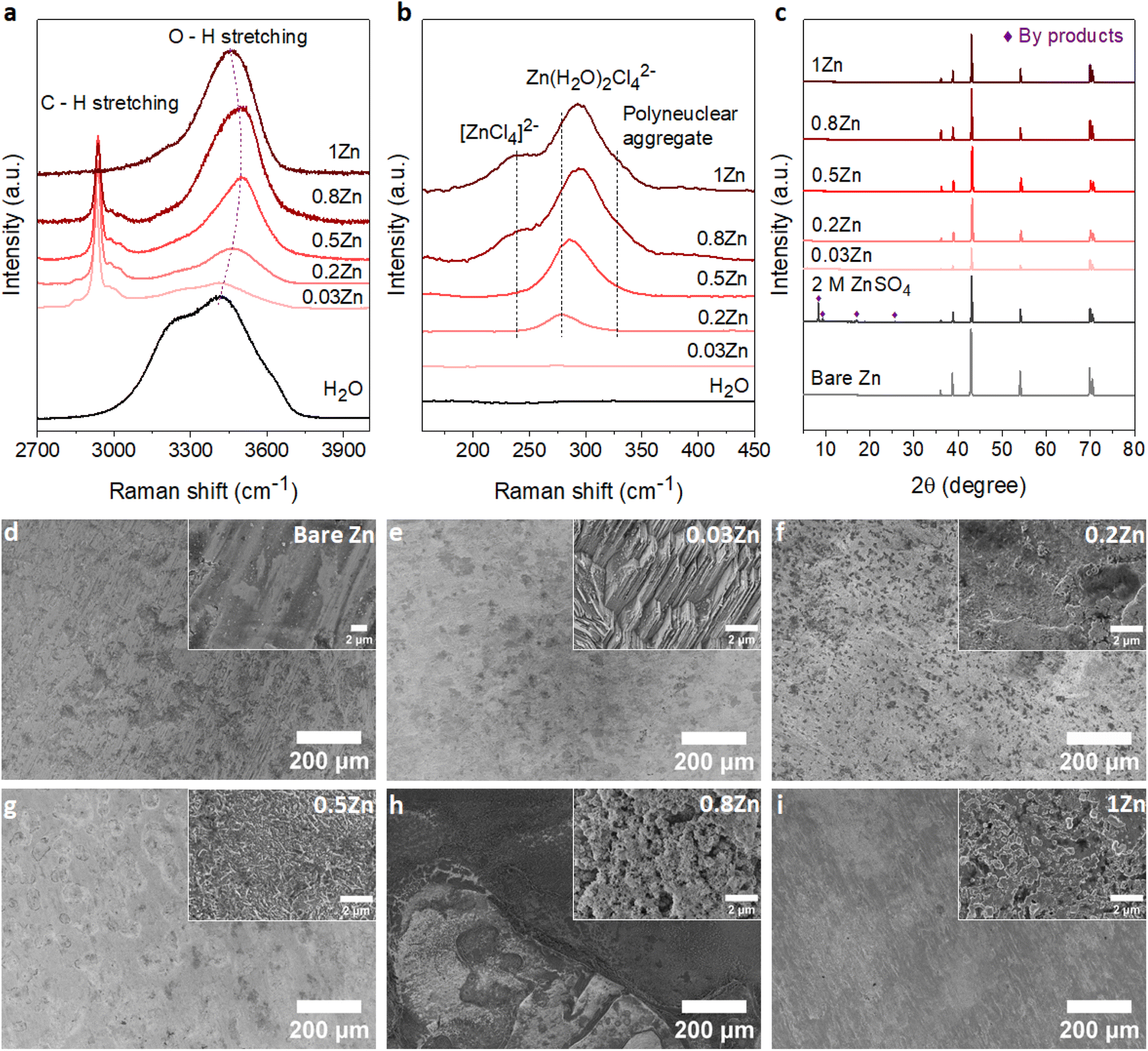 | ||
| Fig. 1 Electrolyte structure and Zn foil stability: (a) and (b) Raman spectra of WISEs corresponding to the water region and Zn coordination, respectively. (c) XRD patterns of the Zn foil before and after immersing in different WISEs for 10 days at room temperature, compared with diluted 2 M ZnSO4. SEM images of (d) bare Zn foil and Zn foil soaked in (e) 0.03Zn, (f) 0.2Zn, (g) 0.5Zn, (h) 0.8Zn, and (i) 1Zn WISEs. | ||
Fig. 1b illustrates the Zn2+ coordination in the low-frequency region (∼140 to 500 cm−1), resulting from the interaction of Zn2+ with H2O molecules and Cl− ions. As expected, no peaks corresponding to 0.03Zn electrolyte are observed in this region due to the absence of Cl− ions. The peak at 278 cm−1 in 0.2Zn electrolyte is assigned to the Zn(H2O)Cl42− complex. The latter shows an increase in intensity and shifting to higher frequencies with increasing Zn molar ratio (Fig. 1b). The additional peaks observed at 240 and 328 cm−1, in 0.8 and 1Zn electrolytes, are attributed to the [ZnCl4]2− complex and Zn–Cl polynuclear aggregate, respectively, according to previously reported studies.14
Furthermore, the coordination of Zn2+ with Ac anions can be examined in the 400–1450 cm−1 range. For a better correlation, the reported WISEs were compared with saturated LiAc (sat. LiAc) solution. The in-plane O–C–O rocking vibration at 476 cm−1 in sat. LiAc completely shifts to higher frequencies upon increasing the ZnCl2 ratio (Fig. S3a†), indicating the interaction of Zn2+ with Ac anions.20 This is similar to the peaks related to COO bending at 656 cm−1, the C–C stretching at 932 cm−1, and C![[double bond, length as m-dash]](https://www.rsc.org/images/entities/char_e001.gif) O stretching at 1419 cm−1, which all undergo a blue shift with ZnCl2 concentration in the prepared WISEs. The CO stretching peak at 1419 cm−1 splits into two for 0.5 and 0.8Zn electrolytes (Fig. S3b†), suggesting simultaneous coordination of Ac to Li+ and Zn2+.20 These results indicate the preference of Ac anions to interact with Zn2+ rather than Li+. Finally, regarding 0.03Zn electrolyte, all the peaks show a red shift in comparison to those of all electrolytes including sat. LiAc. These results indicate the dominant interaction of K+ to Ac anions due to low amount of Zn2+ cations in 0.03Zn electrolytes.
O stretching at 1419 cm−1, which all undergo a blue shift with ZnCl2 concentration in the prepared WISEs. The CO stretching peak at 1419 cm−1 splits into two for 0.5 and 0.8Zn electrolytes (Fig. S3b†), suggesting simultaneous coordination of Ac to Li+ and Zn2+.20 These results indicate the preference of Ac anions to interact with Zn2+ rather than Li+. Finally, regarding 0.03Zn electrolyte, all the peaks show a red shift in comparison to those of all electrolytes including sat. LiAc. These results indicate the dominant interaction of K+ to Ac anions due to low amount of Zn2+ cations in 0.03Zn electrolytes.
2.2. Stability of Zn foil in different WISEs
According to Raman results, water molecules interact with anions and cations present in each WISE in distinct ways. Prior to electrochemical tests, immersion experiments were conducted to assess the impact of these WISEs on the thermodynamic stability of Zn metal anodes. For this, a piece of Zn foil was immersed in the prepared WISEs for a period of 10 days, subsequently rinsed with deionized water, and dried under vacuum. The surface change of Zn foil before and after soaking was then analyzed using X-ray powder diffraction (XRD) and scanning electron microscopy (SEM). For comparison, the XRD patterns of the Zn foil immersed in WISEs were compared with those immersed in 2 M ZnSO4 and 1 m ZnCl2 diluted electrolytes. As expected, 2 M ZnSO4 shows a distinct byproduct formation, which is identified as the Zn4SO4(OH)6·5H2O byproduct (see Fig. 1c),21 while only one characteristic byproduct peak is observed in 1 m ZnCl2 (Fig. S4†).22 In contrast, no XRD patterns of byproducts are observed on the Zn foil soaked in different WISEs. This suggests that byproduct formation is influenced by both the type of Zn salt and concentration. In addition, SEM images are obtained to analyze the surface of Zn metal in relation to the Zn molar ratio (Fig. 1d–i). Bare Zn foil has a rough and uneven surface as indicated in Fig. 1d, which could have been caused by the manufacturing process. As shown in Fig. 1e, the electrode displays surface etching with a structured pattern of parallel lines in 0.03Zn electrolyte. Dark spots and small white mossy particles cover the Zn surface in 0.2 and 0.5Zn electrolytes (Fig. 1f and g), while the Zn surface in 0.8 and 1Zn (Fig. 1h and i) displays pitting spots and particle formation, especially in 0.8Zn electrolyte. The latter is related to corrosion byproducts due to increased acidity. Overall, in all WISEs clear corrosion is observed only at higher magnification except for 0.8Zn. The immersion test reveals that the side reactions generated from the direct interaction between the Zn anode and WISEs are fewer in comparison to those for diluted electrolytes.2.3. Zn electrodeposition behavior
To examine the effect of the Zn molar ratio on H2 evolution and Zn reduction potential in different WISEs during electrodeposition processes, linear sweep voltammetry (LSV) measurements were conducted. Indeed, it is common that in Zn2+ containing aqueous electrolytes, the H2 evolution occurs during Zn electrodeposition at a similar reduction potential.23 As a result, to distinguish Zn reduction from H2 evolution, the WISEs were compared to a Zn-free electrolyte, here 5 m NaCl solution. The experiments were performed using titanium foil (Ti) as the working electrode, Ag/AgCl as the reference electrode, and platinum as the counter electrode at a scan rate of 10 mV s−1. The 5 m NaCl solution reveals a reduction potential occurring at −1.4 V (Fig. 2a), indicative of H2 evolution, given the absence of Zn2+ in the NaCl solution. In contrast, the onset reduction potential of 0.03Zn electrolyte is −1.36 V, which corresponds to the Zn2+ reduction voltage – given that the water content is very low. As the Zn ratio increases from 0.2 to 1, reduction potentials of −1.14, −0.92, −0.75, and −0.63 V are observed. Moreover, we conducted additional LSV experiments on a glassy carbon (GC) substrate using a three-electrode system at scan rates of both 10 and 1 mV s−1 (Fig. S5a and b,† respectively). The resulting reduction potentials in each electrolyte were similar to those obtained with a Ti substrate, indicating similar kinetics limitations using different substrates and scan rates. This result is consistent with previous findings in the literature by using different ZnCl2 concentrations ranging from 1 to 30 m.11,24 Therefore, the positive Zn reduction potential observed with increasing Zn molar ratios is primarily attributed to the increased Zn2+ activity due to the lower acidity of the electrolyte, according to the Nernst equation below: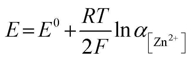 | (1) |
 | ||
| Fig. 2 H2 evolution and Zn deposition potentials in different WISEs. (a) LSV profiles of different electrolytes at 10 mV s−1 using a three-electrode system on a Ti substrate. (b) Galvanostatic Zn electrodeposition on Ti in Zn‖Ti half cells at 1 mA cm−2 and 0.5 mA h cm−2 using different WISEs. Inset: schematic illustration showing nucleation overpotential (ηn), plateau overpotential (ηp), and the change in overpotential (Δη). (c) The corresponding change in ηn, ηp, and Δη with the Zn molar ratio. | ||
The suppression of H2 evolution may not consistently indicate dendrite free Zn deposition. Additional insights into the effect of Zn2+ concentration in the electrolyte on Zn deposition are necessary. It is widely acknowledged that the final morphology of deposited metal relies on the initial nucleation behavior.27 Understanding the mechanism of nucleation behavior is crucial for addressing the formation of Zn dendrites which can be assessed through nucleation overpotential (ηn), driving the nucleation of Zn embryos.28 A smaller nucleation overpotential implies a lower energy barrier for initiating the Zn nucleation process, thereby facilitating uniform Zn nucleation site formation.29,30 Hence, cyclic voltammetry (CV) experiments were conducted in a three-electrode system on Ti foil and GC substrates as the working electrode, platinum wire as the counter electrode, and Ag/AgCl as the reference electrode, with a scan rate of 10 mV S−1 within the potential range of −1.7 to 1.0 V. The CV curves (Fig. S7†) for both electrodes exhibit similar Zn deposition/dissolution behavior across various WISEs, indicating reversibility and the absence of new redox reactions. However, the redox potential shifts to the right with increasing Zn ratio due to higher Zn2+ activity at greater Zn2+ concentrations. Additionally, ηn can be calculated from the potential difference between point (A), where Zn2+ ions begin to reduce, and the crossover at point (A′) formed during the right potential sweep as depicted in Fig. S8.† The ηn measured using a Ti electrode decreases as the Zn2+ concentration increases: 103, 65, 43, and 37 mV corresponding to 0.03, 0.2, 0.5, 0.8, and 1Zn electrolytes, respectively. However, with the exception of the 0.5Zn electrolyte, no clear potential difference between A and A′ was observed, which cannot be explained.
Furthermore, the galvanostatic Zn deposition process is commonly employed not only to determine ηn but also to assess another crucial parameter linked to growth, known as the plateau overpotential (ηp). ηn represents the magnitude of the potential spike at the onset of Zn deposition, while ηp denotes the potential at the plateau following nucleation (see Fig. 2b).31 Additionally, the overpotential difference (Δη) is defined as the gap between ηn and ηp. The ηn values are notably larger than the ηp values in all electrolytes due to the higher energy barrier involved in forming a stable Zn atomic cluster (embryo) compared to adding a Zn atom onto existing Zn nuclei (Fig. 2c), indicating that the electrodeposition of Zn follows the instantaneous nucleation process.32 For instance, the ηn decreases as the Zn molar ratio increases: 311, 234, 86, 50, and 40 mV for 0.03, 0.2, 0.5, 0.8 and 1Zn electrolytes, respectively (Fig. S9†). Simultaneously, the ηp values are 145, 187, 60, 25, and 19 corresponding to 0.03, 0.2, 0.5, 0.8 and 1Zn electrolytes, respectively. Similarly, Δη decreases with the Zn molar ratio; 166, 47, 26, 25, and 19 mV for 0.03, 0.2, 0.5, 0.8, and 1Zn electrolytes, respectively. The results show that a high Zn2+ concentration reduces the energy barrier for Zn nucleation and growth, likely due to reduced kinetics/diffusion resistance – promoting homogeneous Zn deposition.30,33
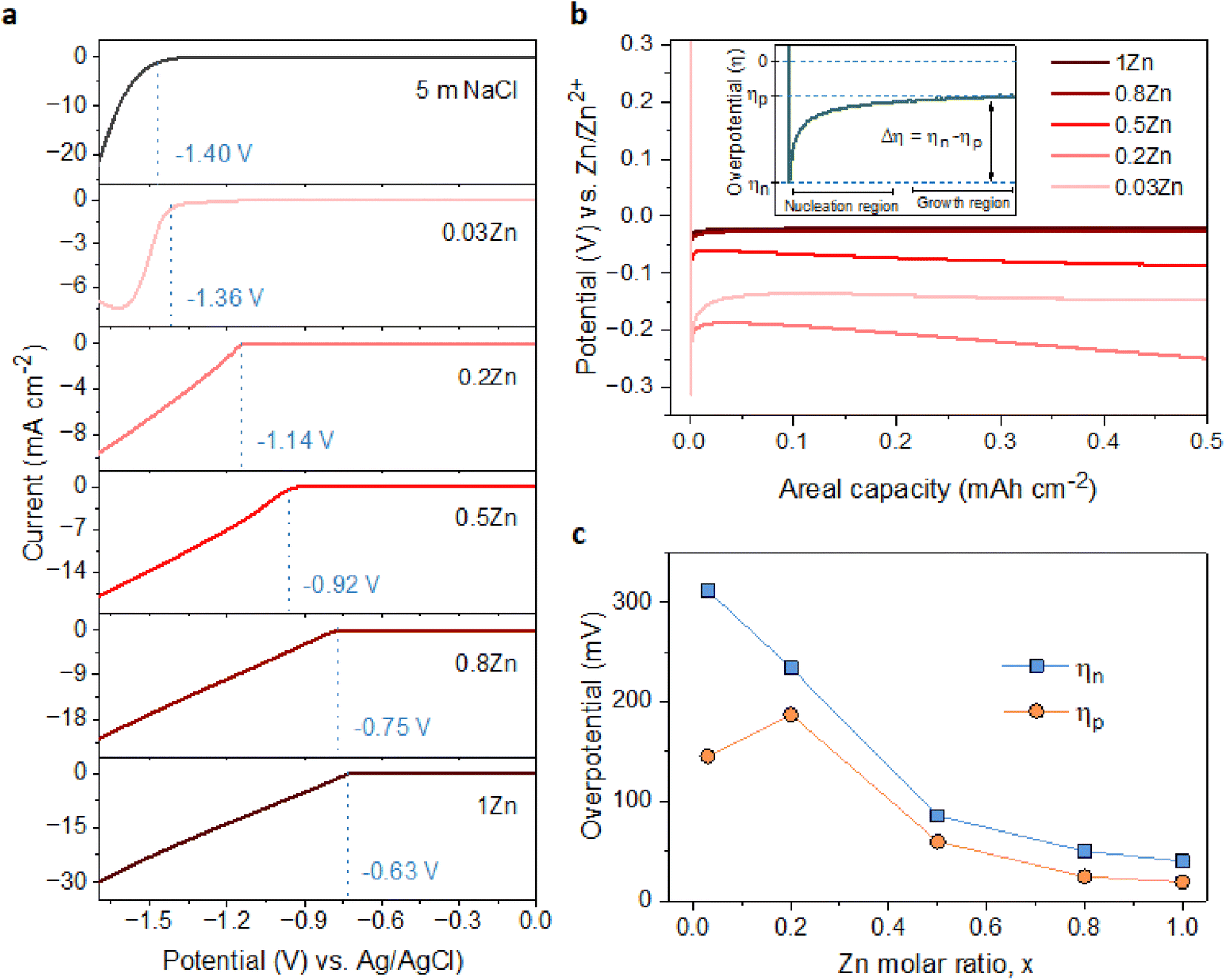
The Zn nucleation and growth behaviors were further analyzed on Zn metal by the chronoamperometry (CA) experiment at a fixed potential of −150 mV for 30 min using Zn‖Zn symmetric cells. The fluctuation of current transients can indicate a change in nucleation processes and surface morphology.27 As depicted in Fig. 3a, the current density exhibits a steady rise over 50, 30, and 5 seconds in 0.03, 0.2, and 0.5Zn electrolytes, respectively, followed by a plateau, suggesting an initial phase of uncontrolled 2D diffusion transitioning into 3D diffusion. During the 2D diffusion process, Zn atoms diffuse laterally to get the energetically favorable sites for deposition,34 which leads to inhomogeneous nucleation on the Zn metal surface and accelerates dendrite growth (Fig. 3b). In contrast, in 0.8 and 1Zn electrolytes, a constant current density was observed from the beginning referred to as a 3D diffusion process (Fig. 3b). This implies that the Zn2+ ions are homogeneously deposited on the Zn electrode surface as the concentration of Zn2+ ions increases. These results are supported by the SEM images of the corresponding deposited Zn in Fig. 3d–g. The electrolyte with the lowest Zn ratio (0.03Zn) shows very small and distributed Zn deposition particles (Fig. 3d). As the Zn molar ratio increases, the size of Zn nuclei increases and they interconnect with each other to form dense and compact Zn deposition (Fig. 3e–h), indicating a 3D deposition process. The results from CA and the corresponding SEM images are consistent with the ηn results in Fig. 3c, demonstrating that a higher Zn molar ratio contributes to uniform and 3D Zn2+ deposition processes. This suppresses dendrite formation by enhancing nucleation sites.29
 | ||
| Fig. 3 Zn diffusion process and the corresponding ion mobility in different WISEs. (a) Chronoamperograms (CAs) of Zn deposition at an applied potential of −150 mV for 900 s. Insets: 2D (left) and 3D (right) diffusion for 0.03, 0.2, and 0.5Zn electrolytes; 3D diffusion for 0.8 and 1Zn electrolytes. Schematics showing (b) 2D and (c) 3D diffusion processes. The corresponding SEM images of deposited Zn in (d) 0.03, (e) 0.2, (f) 0.5, (g) 0.8, and (h) 1Zn electrolytes. (i) The transference number in different electrolytes. | ||
Furthermore, the cationic mobility in the bulk electrolyte is examined through the transference number which represents the ionic current carried by cations only. The Zn2+ transference number (tZn2+) was measured using the steady-current method, employing a constant applied potential to generate a current–time (I–t) transient using Zn‖Zn symmetric cells (Fig. S10†).35,36 The tZn2+ for 0.03, 0.2, 0.5, 0.8, and 1Zn WISEs are calculated to be 0.11, 0.23, 0.28, 0.65, and 0.70, respectively. This indicates that electrolytes containing high Zn2+ concentrations exhibit higher tZn2+ compared to those with lower concentrations, suggesting that Zn2+ ions serve as the primary mobile ions to reduce polarization.37 This explains why the η decreases when the Zn2+ ion concentration increases, as demonstrated in Fig. 2b and c. Moreover, the high tZn2+ effectively enhances the anode's electrochemical performance, and significant tZn2+ can mitigate dendrite growth.19 Additionally, the transport properties of WISEs including ionic conductivity, viscosity and ionicity were further characterized and compared to tZn2+. The viscosity values for 0.03, 0.2, 0.5, 0.8, and 1Zn electrolytes are 48, 537, 265, 317, and 465 mPa s, respectively, while the corresponding ionic conductivity values are 29, 4, 8, 5, and 6 mS cm−1, respectively (Table S1†). All WISEs display low ionic conductivity and high viscosity except 0.03Zn electrolyte which displays the opposite trend (Fig. S11a†). The latter may be attributed to the high solubility of KAc and the lower acidity of K+ which results in lower ion pairing and allows for greater ion mobility, further enhancing ionic conductivity. These findings confirm that the increase in the tZn2+ is directly related to the Zn molar ratio. Furthermore, a Walden plot was used to investigate the relationship between the ionic conductivity and viscosity which reflects the ionicity of the electrolytes. Fig. S11b† indicates no direct correlation between the Zn molar ratio and ionicity, which is expected. Electrolytes with Zn molar ratios of 0.03, 0.2, and 0.5Zn exhibit a higher degree of dissociation, with 0.03 and 0.2Zn displaying super ionicity as they are located above the KCl ideal line. In contrast, the other electrolytes, including 0.8, 1Zn, and diluted 0.5Zn, show a slightly lower degree of ionicity, of around 90%.
2.4. Zn anode cycling stability
The Zn plating/stripping stability was evaluated in Zn‖Zn symmetrical cells at current densities of 1 and 2 mA cm−2, maintaining an areal capacity of 0.5 mA h cm−2. The cycle lifespans of cells in 0.03Zn, 0.2Zn, 0.5Zn, 0.8Zn, and 1Zn WISEs at 1 mA cm−2 are 85, 55, 300, 350, and 500 hours, respectively (Fig. S12a†). The results indicate an improved cycling stability upon increasing the Zn ratio except for 0.2Zn electrolyte which exhibits a slightly shorter cycle lifespan compared to 0.03Zn electrolyte. In addition, lower plating-stripping overpotentials are observed for electrolytes with higher Zn molar ratios from ∼0.35 V in 0.03 to ∼0.1 V in 1Zn (Fig. S12b†). Increasing the current density to 2 mA cm−2 with the same areal capacity of 0.5 mA h cm−2 results in cells failing after 25 hours of cycling in 0.03 and 0.2Zn electrolytes, while cells in 0.5Zn, 0.8Zn, and 1Zn electrolytes sustain 200 hours of cycling (Fig. 4a). The corresponding overpotentials in 0.03Zn and 0.2Zn electrolytes are around 0.7 V, while in 0.5Zn, 0.8Zn, and 1Zn electrolytes, overpotentials slightly decrease with increasing Zn ratios to 0.3 V for 0.5Zn and 0.18 V for 0.8Zn and 1Zn electrolytes (Fig. 4b). The overpotential in 0.5Zn electrolyte slightly increased with cycling time, while for 0.8Zn and 1Zn, it remains constant. The decrease in overpotential as the Zn molar ratio increases underscores the role of Zn2+ mobility in reducing overpotential. Deviation of the overpotential from the ideal value of 0 V vs. Zn/Zn2+ during the Zn plating/stripping process suggests contributions from several factors, including H2 evolution, corrosion byproducts such as Zn(OH)2 and ZnO, or a low transference number.23,27 All electrolytes exhibit reduced water content, suggesting suppression of H2 evolution during Zn plating/stripping. Consequently, Zn2+ concentration becomes a determining factor in compensating for Zn loss attributed to the formation of Zn(OH)2 and ZnO. Therefore, achieving an optimal Zn2+ concentration in WISEs becomes crucial for enhancing the stability of Zn anodes. Hence, electrolytes with 0.5Zn, 0.8Zn, and 1Zn compositions demonstrate favorable reversibility and plating kinetics of Zn.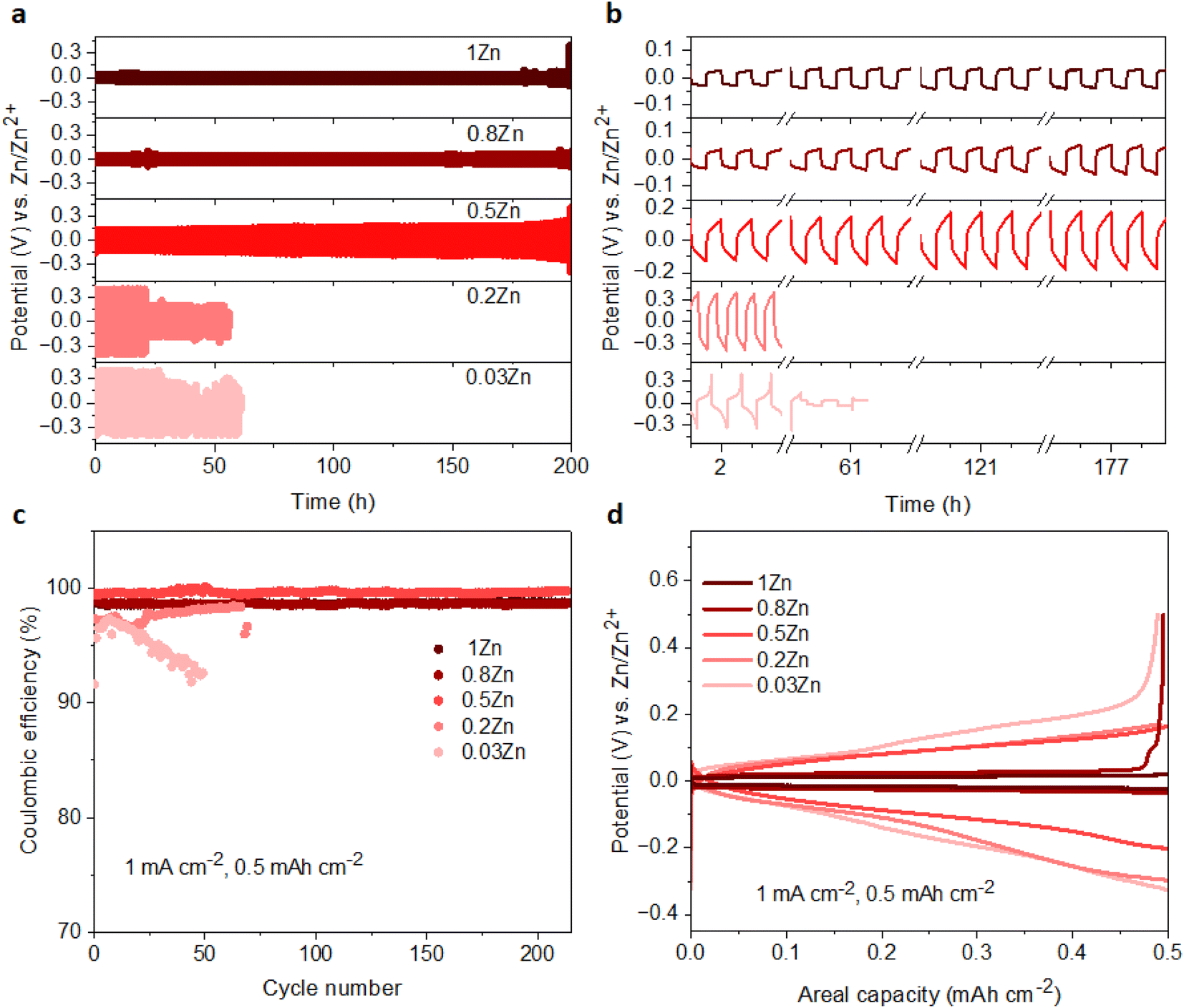 | ||
| Fig. 4 Zn plating/stripping stability. Potential profiles for Zn‖Zn cells obtained in 0.3, 0.2, 0.5, 0.8, and 1Zn electrolytes at current densities of (a) 2 mA cm−2 and 0.5 mA h cm−2 and (b) the corresponding overpotentials in different cycles. (c) CE of Zn plating/stripping on a Cu substrate in different electrolytes at 1 mA cm−2 and 0.5 mA h cm−2 current and capacity densities, respectively. (d) The corresponding potential profiles at the 40th cycle. | ||
Moreover, the coulombic efficiency (CE) serves as a pivotal metric for assessing the reversibility of the Zn anode. To mitigate the influence of Zn2+ ions originating from the Zn electrode, CE assessments should be conducted using a different substrate. Consequently, the CE of Zn plating/stripping across various WISEs was evaluated employing Zn‖Cu at a current density of 1 mA cm−2 and a capacity of 0.5 mA h cm−2, as shown in Fig. 4c. Initial CEs of 91.6, 97.3, 99.4, 99.1, and 98.7% are obtained in 0.03, 0.2, 0.5, 0.8 and 1Zn electrolytes, respectively. The cells using 0.03 and 0.2Zn electrolytes fail after 50 and 70 cycles with an average CE of 94.9 and 96.9%, respectively. Low CE values are observed in Zn-deficient electrolytes during Zn plating/stripping in contrast to the cells employing 0.5, 0.8, and 1Zn electrolytes demonstrating a stable reversibility with average CEs of 99.6, 98.6, and 98.6% after 214 cycles, respectively. Remarkably, the CE value generally increases with increasing Zn2+ concentration, except for the 0.5Zn electrolyte, where the highest CE is observed. However, no significant differences are observed among CE values starting from a 0.5Zn ratio. Furthermore, a similar trend in CE is shown using Ti as the substrate in Zn‖Ti half-cells (Fig. S13†) at 1 mA cm−2 and 0.5 mA h cm−2. Short cycling life is obtained in 0.03Zn and 0.2Zn electrolytes; however, as the concentration of Zn2+ increases the cell runs for 100, 180, and 260 cycles with >96% CE in 0.5Zn, 0.8Zn, and 1Zn electrolytes, respectively.
Furthermore, Fig. 4d and S14† display the potential profiles in Zn‖Cu half-cells which demonstrate lower and stable plateau overpotentials as the Zn ratio increases. A higher overpotential of 183 mV is obtained in 0.03Zn electrolyte, whereas overpotentials of 164, 135, 47 and 30 mV are obtained in 0.2, 0.5, 0.8, and 1Zn electrolytes after the 40th cycle, respectively. The above results show that a Zn molar ratio of 0.5 and above provides better Zn anode performance compared with 0.03 and 0.2, thus suggesting that an optimum Zn2+ concentration should be present in the electrolyte rather than simply increasing the supporting salt to achieve WISE region. This in turn reduces the interfacial resistance related to the supporting salt, which is manifested by the lower overpotentials and polarization for Zn plating/stripping. According to these results, Zn molar ratios less than 0.5 have a significant influence, whereas those greater than 0.5 have less influence, indicating the need for an optimal Zn2+ concentration to achieve enhanced Zn plating/stripping in WISEs.
2.5. Zn surface composition after cycling
To further examine the influence of the Zn molar ratio on facilitating uniform Zn2+ deposition, the surface morphology of Zn and the resulting interphase following cycling were analysed employing SEM and X-ray photoelectron spectroscopy (XPS) techniques.First, the morphology of the Zn anode after 20 cycles at 1 mA cm−2 current and 0.5 mA h cm−2 capacity density was investigated by SEM. The SEM images of the Zn anode show uneven morphology with black spots and pits in 0.03Zn electrolyte (Fig. 5b), which may be due to corrosion byproduct formation. The 0.2Zn electrolyte (Fig. 5c), on the other hand, displays deposition of small particles distributed on the Zn surface while these particles are multiplicated in 0.5Zn indicating a more porous surface (Fig. 5d). The Zn surface becomes denser and compact as the Zn ratio increases in 0.8 and 1Zn electrolytes (Fig. 5e and f). The SEM results show that there is no direct correlation between all Zn molar ratios, particularly those below 0.5Zn. However, the surface of Zn foil is less rough with lower surface porosity upon increasing the Zn molar ratio from 0.5Zn. In addition, the magnified image of the electrode, in particular in the 1Zn electrolyte, reveals a more compact and denser morphology. XPS analysis was conducted to further examine the chemical composition of the cycled Zn surface. The C 1s peaks (Fig. 5g) are deconvoluted into three components. The binding energies at 284.8 and 286.3 eV are attributed to C–C and C–O peaks, respectively, while the peak at 289 eV is assigned to CO3. However, the peak at 286.3 eV is observed only in 0.8Zn electrolyte, indicating the formation of more carbonate containing species. The C 1s peaks in 1Zn electrolyte may be originated from adsorbed organic residue contamination. The O 1s spectra (Fig. 5h) demonstrate the presence of three components corresponding to OCO (532 eV), O–Cl (531.4 eV), and Zn–O (530.6 eV) in 0.2, 0.5, 0.8, and 1Zn electrolytes, indicating the existence of inorganic residues from electrolyte decomposition. For 0.03Zn electrolyte, since there is no chlorine, only C–O and Zn–O bonds of Zn carbonate and Zn oxides are observed. The Cl 2p spectra show two chlorine species corresponding to inorganic and organic chlorine at 198.9 and 200.9 eV (Fig. 5i). Moreover, the 2p orbital of Zn is separated into two peaks (Fig. S15†), corresponding to 2p3/2 (1021.9 eV) and 2p1/2 (1045 eV). The above result indicates that the cycled Zn surface contains an organic/inorganic layer, the organic species generated form acetate (Ac) decomposition while the chlorine and Zn containing inorganic species are derived from ZnCl2. Overall, the compositions of each species generated from electrolyte decomposition on the Zn anode surface after cycling are similar in different electrolytes.
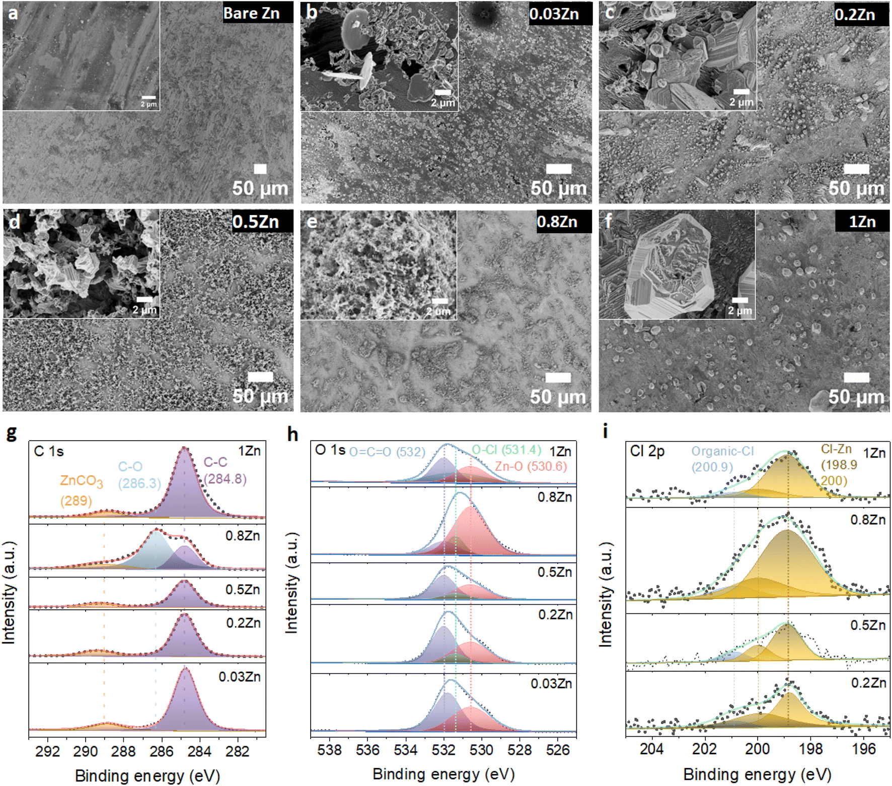 | ||
| Fig. 5 Morphology evolution and surface composition of Zn electrodes after 20 cycles of Zn plating/stripping in different WISEs at 1 mA cm−2 and 0.5 mA h cm−2. SEM images of (a) bare Zn and a cycled Zn anode in (b) 0.03, (c) 0.2, (d) 0.5, (e) 0.8, and (f) 1Zn electrolytes. The corresponding (g) C 1s, (h) O 1s, and (i) Cl 2p XPS spectra. | ||
2.6. WIS-like dilute electrolyte
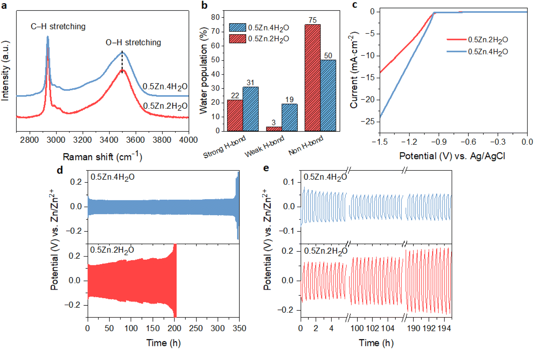
The above results showed that the suppression of free water in WISEs is not enough for the stability of the Zn anode; instead, it is the Zn molar ratio that plays an important role. On the other hand, the water-deficient and anion-rich solvation structure of Zn2+ can also be achieved in dilute electrolytes if the solvation ability of anions is higher than that of water.15,38 Recently, this idea was demonstrated in Zn(Ac)2·2H2O and KAc hybrid electrolyte since the Ac anions have a stronger coordination ability to Zn2+ than water. Specifically, optimal CE and rate performance were attained with a water-to-cation ratio of 10 in the Zn0.2K0.8OAc1.2·10H2O electrolyte (abbreviated here as 0.2Zn·10H2O).15 To validate this concept within our prepared WISEs [(ZnCl2)x(LiAc)1−x/(H2O)n], we chose the 0.5Zn electrolyte because it contains a high amount of Ac anions and considered the optimal ratio for improving CE and rate performance.The 0.5Zn (labeled as 0.5Zn·2H2O hereafter) WISE was diluted to 15 m by increasing the water-to-cation ratio (n) to 4 (labeled as 0.5Zn·4H2O). Raman spectroscopy was employed to investigate the H-bonding environments of water in the 0.5Zn·4H2O electrolyte and compared with that of 0.5Zn·2H2O. As shown in Fig. 6a, the Raman spectra of the 0.5Zn·4H2O electrolyte display broader peaks compared to those of 0.5Zn·2H2O, indicating a higher concentration of water molecules relative to Ac anions. Furthermore, the deconvoluted spectra of the 0.5Zn·4H2O compared to 0.5Zn·2H2O electrolytes reveal distinct hydrogen-bonding environments in the water region. As shown in Fig. 6b and S16a,† the area under the sub-band associated with strongly hydrogen-bonded water molecules in the 0.5Zn·4H2O electrolyte (31%) is slightly higher compared to that of the 0.5Zn·2H2O electrolyte (22%). Notably, the corresponding peak position exhibits a slight shift towards lower frequencies in the 0.5Zn·4H2O electrolyte (3255 cm−1) compared to 0.5Zn·2H2O (3285 cm−1) (Fig. S16b†). In addition, the weak hydrogen-bond peak area increased from 3% to 19% in the diluted 0.5Zn·4H2O electrolyte. The peak area attributed to non-hydrogen-bonded water is 54% in 0.5Zn·4H2O, which decreased in comparison to that of 0.5Zn·2H2O electrolyte. Thus, the higher proportion of strongly hydrogen-bonded water molecules and lower proportion of non-hydrogen-bonded water in 0.5Zn·4H2O compared to 0.5Zn·2H2O suggests the presence of free water molecules.
 | ||
| Fig. 6 Solvation structure and electrochemical stability of the Zn anode in 0.5Zn·4H2O electrolyte compared to concentrated 0.5Zn·2H2O. (a) Raman spectra in the water region. (b) The corresponding water population percentages. (c) LSV curves on a Ti substrate (d) Zn plating/stripping at 2 mA cm−2 and 0.5 mA h cm−2 in Zn‖Zn symmetric cells and (e) the corresponding potential profiles. | ||
The influence of free water molecules on Zn surface morphology and corrosion byproducts was investigated following the immersion test in the 0.5Zn·4H2O electrolyte for 10 days. Subsequent analysis using XRD techniques reveals no XRD patterns indicative of corrosion byproducts (Fig. S17a†). However, the SEM images show many black spots and mossy particles (Fig. S17b†), suggesting the formation of byproducts due to the presence of free water molecules.
The CV analysis of Zn plating/stripping on Ti foil in 0.5Zn·4H2O electrolyte exhibits comparable profiles to those observed in the 0.5Zn·2H2O electrolyte (Fig. S18a†), suggesting the absence of new electrochemical reactions. However, the cell utilizing 0.5Zn·4H2O shows a higher nucleation overpotential (14 mV) compared to that of 0.5Zn·2H2O. The corresponding LSV curve (Fig. 6c) demonstrates a notably higher cathodic current in 0.5Zn·4H2O electrolyte compared to the 0.5Zn·2H2O electrolyte, confirming the contribution of H2 evolution in 0.5Zn·4H2O electrolyte.
Furthermore, the effect of free water molecules in 0.5Zn·4H2O electrolyte on the nucleation and growth process of Zn was investigated through CA using Zn‖Zn symmetric cells similar to the previous protocol (Fig. S18b†). The Zn anode in 0.5Zn·4H2O electrolyte shows a 2D diffusion process for 19 s longer than in 0.5Zn·2H2O, followed by a constant 3D diffusion process thereafter. However, the corresponding SEM images in Fig. S18d† display similar size and morphology to the particles in concentrated 0.5Zn·2H2O – indicating similar growth mechanisms. Furthermore, the tZn2+ in 0.5Zn·4H2O electrolyte is 0.54 (Fig. S18c†), which is higher than that in 0.5Zn·2H2O electrolyte due to lower viscosity combined with increased ionic conductivity (Table S1†).
The Zn anode plating/stripping reversibility in 0.5Zn·4H2O electrolyte was demonstrated using a Zn‖Zn half-cell at different current densities with a fixed capacity of 0.5 mA cm−2, as demonstrated in Fig. 6d, e and S19.† The cell utilizing the 0.5Zn·4H2O electrolyte failed after 130 cycles at a lower current density of 1 mA cm−2, whereas the cell with the 0.5Zn·2H2O electrolyte sustains for 300 cycles (Fig. S19a and b†). In contrast, the cell with the 0.5Zn·4H2O electrolyte at 2 mA cm−2 current density sustains over 350 cycles without experiencing potential fluctuations, whereas the cell using 0.5Zn·2H2O electrolytes experienced short circuits after around 200 cycles (Fig. 6d and e). These results demonstrate that the 0.5Zn·4H2O electrolyte offers superior Zn stability at higher current densities, while the reverse is observed at lower current densities, consistent with the LSV data in Fig. 6c.
The diluted electrolyte was also compared to the recently reported WIS-like Zn0.2K0.8OAc1.2·10H2O electrolyte (abbreviated as 0.2Zn·10H2O).15 As depicted in Fig. S19c and d,† the Zn‖Zn cell with the 0.2Zn·10H2O electrolyte cycled for over 150 cycles with significant potential fluctuations at 1 mA cm−2 and 0.5 mA h cm−2, while the 0.5Zn·4H2O electrolyte provides 130 cycles but without any potential fluctuation. Doubling the current density with the same capacity yields approximately 160 cycles in the 0.2Zn·10H2O electrolyte with higher overpotential. However, the 0.5Zn·4H2O electrolyte delivers over 350 cycles without any potential fluctuation compared to the 0.2Zn·10H2O electrolyte. Again these results indicate the importance of the Zn molar ratio for Zn cycling stability in particular at high current density. Note that the obtained stability of 0.2Zn·10H2O is different in this work from that in the reported paper. This can be explained by the difference in the Zn anode size, where here we used 13 mm in contrast to the 6 mm diameter. As the Zn electrode size decreases, better contact between electrodes results from increased pressure. This heightened pressure, in turn, influences the ion flux and distribution of current. Hence, the homogenization of the Zn anode size is important for future research.
Finally, the cycled Zn electrodes after 20 cycles at 1 mA cm−2 and 0.5 mA h cm−2 were analysed using SEM and XPS. The SEM image illustrates a similar morphology to the Zn electrode in 0.5Zn·2H2O electrolyte (Fig. 5d). However, the Zn electrode in the 0.5Zn·4H2O electrolyte displays a more porous and non-uniform structure (Fig. S20†), indicative of dendrite growth and byproduct formation likely caused by the presence of free water molecules. The composition of the cycled Zn electrode was further analyzed by XPS. As shown in Fig. S21a,† the survey spectra indicate the presence of C, O, Zn, and Cl elements. The presence of characteristic C 1s peaks at 284 eV (C–C) and 289 eV (CO3) in Fig. S21b† suggests the adsorption or decomposition of Ac anions on the surface of the Zn electrode. The O 1s spectra reveal the presence of C–O and C–Cl species (Fig. S21c†), while the Cl 2p (Fig. S21d†) spectra exhibit organic and inorganic chlorine species. The type and position of each peak in this electrolyte are consistent with those observed in the 0.5Zn·2H2O electrolyte discussed previously. The organic species may originate from Ac, while the inorganic species may be derived from ZnCl2. Therefore, these findings indicate that optimizing the mixing salt ratio in dilute solutions also enhances Zn anode stability, particularly at higher current densities, if WIS-like coordination of Zn2+ ions is achieved.
3. Conclusion
In summary, we conducted a systematic investigation into how varying Zn molar ratios affect the nucleation behavior, deposition process, and cycling stability of Zn metal anodes across different WISEs. Our findings reveal a direct correlation between Zn overpotentials, the deposition process, and cycling stability and the concentration of Zn2+ in the electrolyte. With increasing Zn molar ratio, there is an expansion in the potential difference between Zn reduction and H2 evolution due to the positive shift in Zn reduction potential. Moreover, we observed the formation of interconnected, larger and dense Zn nuclei on Zn foil at increased Zn molar ratios. This phenomenon can be attributed to lower nucleation and growth overpotentials resulting from increased nucleation sites with increasing Zn2+ concentration. Consequently, Zn metal anodes perform better in 0.5, 0.8, and 1Zn WISEs compared to 0.03 and 0.2Zn WISEs, owing to enhanced tZn2+ and lower overpotentials. Cycling stability analysis indicates an optimal Zn molar ratio of around 0.5. Beyond the latter ratio, the Zn molar ratio primarily affects only Zn plating/stripping overpotentials while maintaining similar cycling times. Furthermore, taking the 0.5Zn electrolyte, the impact of water content was studied by diluting the solution by half. For the examined diluted electrolyte (0.5Zn·4H2O), a WISE-like coordination environment is achieved around Zn2+, enabling high rate performance to be achieved compared to that of most other concentrated electrolytes. However, this is at the expense of lower stability at low current density due to promoted H2 evolution as a result of increased free water population. Hence, this study shows the importance of increasing the Zn salt concentration during the preparation of WISEs. An optimum Zn molar ratio of 0.5 was found which is already considered high in comparison to that of most reported WISEs in the literature. Hence, this study provides a new insight for the future design of WISEs to achieve high performance AZIBs.Data availability
The data supporting this article have been included as part of the ESI.†Conflicts of interest
The authors declare no competing interests.Acknowledgements
This work was supported by the Max Planck Society. F. W. F. acknowledges the Alexander von Humboldt Stiftung for financial support. R. B. acknowledges funding by the European Union's Framework Program for Research and Innovation Horizon 2020 (2014–2021) under the Marie Skłodowska-Curie Grant Agreement No. 101032227. Open Access funding provided by the Max Planck Society.References
- Y. Zou, X. Yang, L. Shen, Y. Su, Z. Chen, X. Gao, J. Zhou and J. Sun, Energy Environ. Sci., 2022, 15, 5017–5038 RSC.
- J. Cao, D. Zhang, X. Zhang, Z. Zeng, J. Qin and Y. Huang, Energy Environ. Sci., 2022, 15, 499–528 RSC.
- Z. Li and A. W. Robertson, Battery Energy, 2022, 2, 1–30 Search PubMed.
- W. Yang, Y. Yang, H. Yang and H. Zhou, ACS Energy Lett., 2022, 7, 2515–2530 CrossRef CAS.
- L. Cao, D. Li, T. Deng, Q. Li and C. Wang, Angew. Chem., Int. Ed., 2020, 59, 19292–19296 CrossRef CAS PubMed.
- O. O. Sofronov and H. J. Bakker, ACS Cent. Sci., 2020, 6, 1150–1158 CrossRef CAS PubMed.
- C. Liu, X. Xie, B. Lu, J. Zhou and S. Liang, ACS Energy Lett., 2021, 6, 1015–1033 CrossRef CAS.
- V. Verma, S. Kumar, W. Manalastas and M. Srinivasan, ACS Energy Lett., 2021, 6, 1773–1785 CrossRef CAS.
- F. Wang, O. Borodin, T. Gao, X. Fan, W. Sun, F. Han, A. Faraone, J. A. Dura, K. Xu and C. Wang, Nat. Mater., 2018, 17, 543–549 CrossRef CAS PubMed.
- C. Zhang, J. Holoubek, X. Wu, A. Daniyar, L. Zhu, C. Chen, D. P. Leonard, I. A. Rodriguez-Perez, J. X. Jiang, C. Fang and X. Ji, Chem. Commun., 2018, 54, 14097–14099 RSC.
- F. Yang, J. A. Yuwono, J. Hao, J. Long, L. Yuan, Y. Wang, S. Liu, Y. Fan, S. Zhao and K. Davey, Adv. Mater., 2022, 34, 2206754–2206766 CrossRef CAS PubMed.
- S. Chen, R. Lan, J. Humphreys and S. Tao, Energy Storage Mater., 2020, 28, 205–215 CrossRef.
- Y. Zhu, J. Yin, X. Zheng, A.-H. Emwas, Y. Lei, O. F. Mohammed, Y. Cui and H. N. Alshareef, Energy Environ. Sci., 2021, 14, 4463–4473 RSC.
- R. Bouchal, I. Al Kathemi and M. Antonietti, Small, 2023, 2309556–2309567 Search PubMed.
- D. Gomez Vazquez, T. P. Pollard, J. Mars, J. M. Yoo, H.-G. Steinrück, S. E. Bone, O. V. Safonova, M. F. Toney, O. Borodin and M. R. Lukatskaya, Energy Environ. Sci., 2023, 16, 1982–1991 RSC.
- I. Bodachivskyi, U. Kuzhiumparambil and D. B. G. Williams, Catal. Sci. Technol., 2019, 9, 4693–4701 RSC.
- D. E. Irish, B. McCarroll and T. F. Young, J. Chem. Phys., 1963, 39, 3436–3444 CrossRef CAS.
- X. Guo and G. He, J. Mater. Chem. A, 2023, 11, 11987–12001 RSC.
- D. Dong, T. Wang, Y. Sun, J. Fan and Y.-C. Lu, Nat. Sustain., 2023, 1674–1684 Search PubMed.
- D. Mendes de Oliveira, S. R. Zukowski, V. Palivec, J. Henin, H. Martinez-Seara, D. Ben-Amotz, P. Jungwirth and E. Duboue-Dijon, Phys. Chem. Chem. Phys., 2020, 22, 24014–24027 RSC.
- C. Li, S. Jin, L. A. Archer and L. F. Nazar, Joule, 2022, 6, 1733–1738 CrossRef.
- H. Jiang, L. Tang, Y. Fu, S. Wang, S. K. Sandstrom, A. M. Scida, G. Li, D. Hoang, J. J. Hong, N.-C. Chiu, K. C. Stylianou, W. F. Stickle, D. Wang, J. Li, P. A. Greaney, C. Fang and X. Ji, Nat. Sustain., 2023, 6, 806–815 CrossRef.
- Y. Wang, T. Wang, S. Bu, J. Zhu, Y. Wang, R. Zhang, H. Hong, W. Zhang, J. Fan and C. Zhi, Nat. Commun., 2023, 14, 1828–1841 CrossRef CAS PubMed.
- B. Gavriel, N. Shpigel, F. Malchik, G. Bergman, M. Turgeman, M. D. Levi and D. Aurbach, Energy Storage Mater., 2021, 38, 535–541 CrossRef.
- M. Amiri and D. Bélanger, ChemElectroChem, 2021, 8, 2737–2745 CrossRef CAS.
- F. Yang, J. A. Yuwono, J. Hao, J. Long, L. Yuan, Y. Wang, S. Liu, Y. Fan, S. Zhao, K. Davey and Z. Guo, Adv. Mater., 2022, 34, 2206754–2206766 CrossRef CAS PubMed.
- Z. Zhao, J. Zhao, Z. Hu, J. Li, J. Li, Y. Zhang, C. Wang and G. Cui, Energy Environ. Sci., 2019, 12, 1938–1949 RSC.
- H. Liu, Y. Zhang, C. Wang, J. N. Glazer, Z. Shan and N. Liu, ACS Appl. Mater. Interfaces, 2021, 13, 32930–32936 CrossRef CAS PubMed.
- J. Wan, R. Wang, Z. Liu, S. Zhang, J. Hao, J. Mao, H. Li, D. Chao, L. Zhang and C. Zhang, Adv. Mater., 2024, 36, 2310623–2310636 CrossRef CAS PubMed.
- Q. Zou, Z. Liang, W. Wang, D. Dong and Y.-C. Lu, Energy Environ. Sci., 2023, 16, 6026–6034 RSC.
- A. Pei, G. Zheng, F. Shi, Y. Li and Y. Cui, Nano Lett., 2017, 17, 1132–1139 CrossRef CAS PubMed.
- K. Yan, J. Wang, S. Zhao, D. Zhou, B. Sun, Y. Cui and G. Wang, Angew. Chem., Int. Ed., 2019, 58, 11364–11368 CrossRef CAS PubMed.
- Y. Zhao, S. Guo, M. Chen, B. Lu, X. Zhang, S. Liang and J. Zhou, Nat. Commun., 2023, 14, 7080–7091 CrossRef CAS PubMed.
- H. Peng, C. Liu, N. Wang, C. Wang, D. Wang, Y. Li, B. Chen, J. Yang and Y. Qian, Energy Environ. Sci., 2022, 15, 1682–1693 RSC.
- D. Han, C. Cui, K. Zhang, Z. Wang, J. Gao, Y. Guo, Z. Zhang, S. Wu, L. Yin, Z. Weng, F. Kang and Q.-H. Yang, Nat. Sustain., 2021, 5, 205–213 CrossRef.
- L. Cao, D. Li, T. Pollard, T. Deng, B. Zhang, C. Yang, L. Chen, J. Vatamanu, E. Hu, M. J. Hourwitz, L. Ma, M. Ding, Q. Li, S. Hou, K. Gaskell, J. T. Fourkas, X. Q. Yang, K. Xu, O. Borodin and C. Wang, Nat. Nanotechnol., 2021, 16, 902–910 CrossRef CAS PubMed.
- Y. Deng, H. Wang, M. Fan, B. Zhan, L. J. Zuo, C. Chen and L. Yan, J. Am. Chem. Soc., 2023, 145, 20109–20120 CrossRef CAS PubMed.
- S. Alvarez, Chem.–Eur. J., 2020, 26, 4350–4377 CrossRef CAS PubMed.
Footnote |
| † Electronic supplementary information (ESI) available. See DOI: https://doi.org/10.1039/d4ta02704c |
| This journal is © The Royal Society of Chemistry 2024 |