DOI:
10.1039/D4TA02852J
(Paper)
J. Mater. Chem. A, 2024,
12, 24409-24416
Insights into hydroelectric nanogenerators: numerical simulation and experimental verification†
Received
25th April 2024
, Accepted 5th August 2024
First published on 6th August 2024
Abstract
The invention of hydroelectric nanogenerators (HENGs) is a breakthrough technology for green electricity generation. However, the underlying mechanisms driving energy conversion remain largely unknown, impeding the development of HENGs with high energy densities. Here, we develop a new Multiphysics model involving Darcy's law, phase transfer in porous media, and current modules to reveal the mechanisms of electricity generation in HENGs. This is the first model to simulate evaporation as a streaming potential variable with the Robin-type boundary condition that overcomes the shortcomings of Neumann- and Dirichlet-type boundary conditions. Including the streaming potential and electric double layer (EDL) effects, the simulation can be based on actual water flow conditions, which is more convincing and lays a microscopic foundation for future research and exploration into the mechanism of hydroelectric electricity generation. The new model reveals that the concentrations of salt solutions significantly impact the output power density of HENGs by affecting the solution conductivity in the stern layer, while relative humidity has a minimal impact. This model along with experimental validation offers a robust method to improve the electrical output of HENGs.
1 Introduction
Hydroelectric nanogenerators (HENGs) produce electricity by relying on water from the surrounding environment and the strong interactions between water and functional nanomaterials.1–6 These nanomaterials are hydrophilic, conductive, and stackable.1,3,7 HENGs have a compact size and excellent energy conversion efficiency, making them ideal for meeting the electricity demand driven by the rapid growth of portable/wearable electronics, such as wearable sensors.3,8,9 The suggested mechanism for electricity generation in HENGs is the water flow-induced creation of a streaming potential in porous media.10–14 It is challenging to understand the mechanism and the influence of various factors on electricity generation based solely on experimental investigation, as these drawbacks hinder the development of HENGs with a high-power density.15–17 Experimental investigations include various solutions, functional materials, and setups, posing challenges for comparison and generalization. Furthermore, the current debate focuses on the streaming potential in the diffusion layer, ignoring the surface potential in the stern layer.18
Two typical steps have been used to calculate the output streaming potential, including electrostatic field control theory and dynamic electric field control theory. In the electrostatic field control theory, a constant value of electrical potential, generally denoted as the zeta (ζ) potential, is set to simulate the charge density by using the Poisson–Boltzmann equation. The Dirichlet-type boundary condition is where ζ is specified at the fluid–solid interface.19 However, there is no current in the calculation. Thus, the charge density is independent of the streaming potential. One possible solution is to constantly adjust the charge value on the boundary based on experimentally measured values.20,21 In electrokinetic field control theory, the tested data are simulated using Ohm's law equation. It is about the relationship between electrodes and electrolytes in electrochemistry. The Neumann-type boundary condition is where a constant value of the normal electric field is specified at the fluid–solid interface, plus the same condition at the channel center (or infinity).18,22,23 However, the boundary is set to ground solid in this case. The solid ground is non-conductive and has no charge density. Therefore, there is no charge exchange and no current flow. In HENGs, the change in normal electric field is zero, and the change in streaming potential is zero, so it is electrically insulating.
Power generation is a combination of electrostatic and dynamic processes. The experimental results cannot be simulated by either the Neumann- or Dirichlet-type boundary condition. In this work, Robin-type boundary conditions are coupled with electrostatic and dynamic processes to simulate the output electrical results.18 The Robin boundary condition has three advantages. (1) The charge density or zeta potential at the boundary varies with the salt concentration and pH of the liquid, rather than having fixed values at the boundary. (2) Although positive and negative ions are spatially separated and constitute the EDL, the total charge in the entire liquid system (including boundary conditions) remains neutral. (3) The entire calculation process does not need the introduction of empirical fitting parameters. Therefore, we have developed a comprehensive theoretical multiphysics model of carbon- and transition metal-based HENGs, such as ketjen black (KB) and MXene-based HENGs, using COMSOL Multiphysics.3,7 The selection of KB is because KB has good structural stability, and high chemical stability. The selection of MXenes is based on their high conductivity and large surface area due to their two-dimensional structure. Our model has three novelties; (1) it uses the Robin-type boundary condition, which addresses the drawbacks of Neumann- and Dirichlet-type boundary conditions. (2) It is the first to simulate evaporation as a streaming potential variable, whereas the streaming potential in previous studies was modelled as a steady flow. (3) The classic equation used to calculate the streaming potential in previous studies is known as the Helmholtz–Smoluchowski equation, which requires the provision of pressure difference conditions. The calculation in our model is based on streaming potential and EDL effects. Simulation calculations can be conducted based on actual water flow conditions, providing a more robust and persuasive basis. This approach establishes a microscopic foundation for subsequent research and the exploration of the hydroelectric power generation mechanism, which is more convincing and lays a microscopic foundation for further research and exploration of the mechanism of hydroelectric electricity generation.
The mechanism in HENGs is shown in Fig. 1. A parametric study was conducted to study the impacts of crucial parameters including humidity, loading of conductive materials (by varying the immersion time of the substrate into the solution of a conductive material), NaCl concentration, salt type, and conductive nanomaterials (e.g., KB and MXenes) on the HENGs. Understanding the influences of these parameters could help gain insights into electricity generation by HENGs and hence the design of efficient HENGs.7 Based on these results, strategies to optimize the output electrical performance of HENGs were proposed.
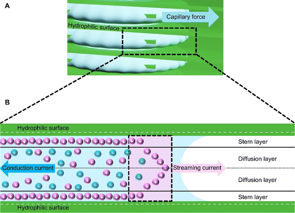 |
| | Fig. 1 The power generation mechanism in HENGs. (A) Hydrophilic surface and capillary force on HENG nanochannels. (B) Schematic diagram of the interaction between water and the hydrophilic surface and bilayer formation at the solid–water interface. | |
2 Materials and methods
Numerical simulations using COMSOL Multiphysics 5.5 were performed to gain insights into the electricity generation process in HENGs. The constructed domain was 0.5 × 4 cm2 which was the actual dimension of the HENG device (Fig. S1 and S2A†).3,7 Voltage generation in HENGs was simulated by three modules including current, Darcy's law, and phase transfer in porous media. Realistic parameter values or literature values were used in the simulations (Table S1†).13,14,24 The phase transfer in the porous medium module was used to determine density changes and evaporation status by using eqn (1)–(6). The unsaturated status in the HENGs' channels is considered as a two-phase (liquid water and water vapor) porous medium (water/air) (eqn (1)).| |  | (1) |
where s1 is the volume fraction of the water phase. The relative transient equations are expressed as eqn (2) and (3).| |  | (2) |
| |  | (3) |
where εp is the porosity of the media, ρi (kg m−3) is the solution density, s1i is the volume fraction of the ith water phase, vi (m3 s−1) is the volume flux of the ith water phase, μi (Pa s) is the ith dynamic viscosity of the solution, Qi (kg m−3 s−1) is the ith mass source, k is the liquid permeability of the porous media, kri is the relative permeability of the water phase of the porous media, Δpi (Pa) is the ith pressure drop of the capillary pressure in HENGs, and g (m s−2) is the gravity acceleration constant. If the pressure of the water phase in the channels of HENGs is set to be independent, then the pressure of the air phase is the relative pressure compared with it. This can be expressed as pi = pic + pci(s1, …, sN), for i ≠ ic. The Brooks–Corey model was applied to describe water retention in porous media with three boundary conditions (eqn (4)–(6)).25Eqn (4) was used to calculate the capillary force.| | | pcapillary = pec × (s1)−1/λp | (4) |
where pec (Pa) is the inlet capillary pressure and λp is the pore size distribution index. The relative permeabilities of the wetting phase and non-wetting phase are shown in eqn (5) and (6).| | | krs2 = s22(1 − (1 − s2)(1+2/λp) | (6) |
where s2 is the channel volume fraction occupied by the air phase. Also, in this module, the applied non-flux boundary condition was set at the solid–fluid interface in the phase transfer in the porous medium module as ns·ρivi = 0, for x ∈ ∂Ω, where ns is the unit normal vector of the solid surface, and Ω denotes the fluid domain.
The Darcy's law module was used to describe the water movement driven by the capillary force in porous media, and to calculate fluidic velocities by using eqn (7) and (8) due to capillary and evaporative effects:25
| |  | (7) |
| |  | (8) |
where
ρ (kg m
−3) is the solution density,
v (m
3 s
−1) is the volume flux of the water phase,
μ (Pa s) is the dynamic viscosity of the solution,
Q (kg m
−3 s
−1) is the mass source, and Δ
p (Pa) is the drop of capillary pressure between the outlet and inlet in HENGs.
The applied non-flux boundary condition (ns·ρivi = 0, for x ∈ ∂Ω) was set at the solid–fluid interface in the Darcy's law module. In addition, the outlet pressure is affected by relative humidity, capillary pressure, air gravity, and vapor pressure.
The current module was used to calculate the streaming potential difference under open circuit conditions by using Maxwell's equations (eqn (9)–(11)).
| |  | (10) |
where
J (A m
−2) is the total current density,
Qj,ψ (kg m
−3 s
−1) is the current flux,
σ (S m
−1) is the specific conductivity of the solution,
E (V m
−1) is the electric field,
D (C m
−2) is the potential displacement field flux,
Je (A m
−2) is the free current density and ∇
ψ (V m
−1) is the potential difference. The applied electrical boundary conditions are
eqn (12)–(14).
where
ε0 (F m
−1) is the vacuum permittivity and
εr is the relative permittivity of the solution defined as the ratio of the dielectric constant of the solution to the vacuum permittivity (
ε0). The applied electrical insulation boundary condition at the solid–fluid interface is set as
nsJ = 0, for
x ∈ ∂
Ω in this module, where
ns is the unit normal vector of the solid surface, and
Ω denotes the fluid domain.
The Helmholtz–Smoluchowski (HS) equation (eqn (15)) was used to calculate the fluidic velocities to couple with Darcy's law.
| |  | (15) |
where
ζ is the local zeta potential of the solid surface and ψstr is the electric potential within the solution.
The detailed flow chart is shown in Fig. S2B† describing the process of solving equations within these modules.
3 Results and discussion
The streaming potential is impacted by RH, porosity, pore size distribution, temperature, active material loading on the substrate, and ionic concentration.1,26 Active material loading can be controlled by using the concentration of active material in the ink and the number of immersions of the substrate into the ink.1,3 In addition, the number of immersions affects the porosity, pore size, and pore size distribution in HENGs, which in turn affects the electrical performance of HENGs (eqn (2) and (4)). Ionic concentration can be controlled by adjusting the salt concentration. Also, the streaming potential is impacted by salt types because the charge storage behavior of these hydrophilic cations is affected by the solvation energy, charge, and size of the cations. The mixtures of various active materials exhibited different electrical outputs due to the interactions of these materials. In this work, the influence of the various parameters including loading of the active material (by varying the immersion times of the substrate (wool cloth) into the ink of an active material), salt (NaCl) concentration, salt type, and properties of the active materials (KB, SMX and their mixtures) on the power generation of HENGs was simulated.
3.1 Immersion times
In the KB-based HENGs, ketjen black nanoparticles (active material) were loaded onto wool cloth, and the loading amount of KB nanoparticles increased with the immersion time.3 As the number of immersions increased, the size of nanochannels decreased. A narrow nanochannel leads to a decrease in the open-circuit voltage (VOC) (Fig. 2 and S3†) based on the Stern model (eqn (16)).18,27,28| |  | (16) |
where ψstr (V) is the electric potential within the solution and d (m) is the thickness of the inner layer.
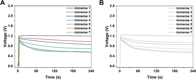 |
| | Fig. 2 Numerical simulations of the electrical performance of KB-based HENGs with various immersions by using 5 M NaCl. Experimental (A) and simulated (B) real-time open-circuit voltages (VOC); (A) is reprinted with permission from ref. 3, copyright 2023, Elsevier. | |
Simultaneously, the internal resistance of KB-based HENGs decreased from 82.67 kΩ (1 immersion) to 1.16 kΩ (6 immersions). Then, wool cloth was saturated with KB reflected by a slight decrease in internal resistance from 6 to 7 immersions. As a result, the output current increased from 1 to 6 immersions, and then remained constant at 7 immersions. Thus, there is a KB concentration boundary for electricity output performance. After 5 immersions, the size of the nanochannels tends to be relatively stable while the loading amount of KB nanoparticles keeps increasing (Fig. 3A and B). The output current density increases with the number of immersion times of the wool cloth (Fig. 3), which increases the load of active materials. A possible reason for the slight increase in the maximum output current (from 6 to 7 immersions) is that the newly added porous structure acts as a secondary capacitor, absorbing charge at the beginning of the liquid flow and slowly releasing the charge to contribute to the output current. The simulated results are consistent with the experimental data both qualitatively and quantitatively. For example, the simulated maximum voltage alteration corresponded well with the voltage generated by KB-based HENGs using 5 M NaCl (Fig. 2). The slight differences in Fig. S3B, C, E, and F† may be attributed to the uneven distribution of KB nanoparticles.
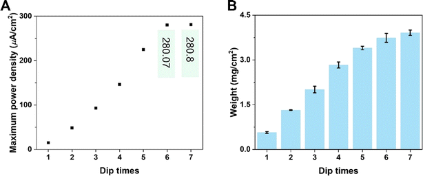 |
| | Fig. 3 Electrical performance of KB-based HENGs. (A) The output maximum power density of KB/W with various immersion times (Zn electrodes and 5 M NaCl were used). (B) KB loading with various immersions on wool cloth. | |
The voltages initially increase rapidly and then decrease (Fig. 2). A possible reason might be that water molecules are absorbed in the HENG channels upon the introduction of the solution. Water molecules interact with active materials in HENGs, dissociating into positive (H+) and negative ions (OH−), thus forming an electric double layer (EDL).29 The EDL consists of a diffusion and a Stern layer (Fig. 1). In the Stern layer, ions remain immobilized and firmly bound to the surface of active materials due to the electrostatic attraction. Within the diffusion layer, ions move directionally under the influence of thermodynamic and electrostatic force effects.30 The evaporation process leads to the motion of water in the active layer due to the capillary forces, resulting in asymmetric wetting of the active layer. Asymmetric wetting causes the directional movement of charge carriers in the external circuit, thereby generating current. This process is accompanied by a potential difference, the streaming potential, which is a continuous and unidirectional voltage. The motion of charge carriers is rapidly driven by capillary forces at the beginning. However, the subsequent evaporation force may not be enough to support the rapid motion of charge carriers, thereby leading to a decrease in voltage.
3.2 NaCl concentration
KB-based HENGs with 6 immersions (KB6/W-based HENGs) output a maximum VOC of 1.018 V by using 2.1 M NaCl, which is much higher than that generated by DI water (0.371 V) (Fig. 4A). This means that NaCl concentration is a key factor impacting the output electrical performance of HENGs. A consequential increase in the surface charge density (σ) occurs as the concentration of NaCl within the solution increases. Meanwhile, the relative dielectric constant of the electrolyte decreases (εr becomes smaller). These alterations collectively contribute to an elevation in the electrical potential VOC (Fig. S4†). Furthermore, the increase in NaCl concentrations in HENGs leads to a decline in the internal resistance of HENGs, ultimately contributing to the amplification of ISC. For example, the maximum output ISC of KB6/W-based HENGs utilizing 2.1 M NaCl solution (683 μA) is around 12.5 times that of KB6/W-based HENGs utilizing DI water (54.65 μA).3
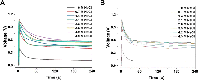 |
| | Fig. 4 Numerical simulations of the electrical performance of KB6/W-based HENGs with NaCl solutions of various concentrations. Experimental (A) and simulated (B) real-time open-circuit voltages (VOC); (A) is reprinted with permission from ref. 3, copyright 2023, Elsevier. | |
Both the experimental (Fig. 4A) and simulation results (Fig. 4B) show that the voltage dropped quickly within the first minute and then approached constant values. However, the experimental values were slightly higher than the simulated values when the salt concentration was higher than a threshold (2.1 M). At this concentration, a VOC of ca. 0.55 V was obtained experimentally, while a lower simulated VOC of ca. 0.51 V was obtained (Fig. S4D†). It is particularly obvious that at a NaCl concentration of 2.8 M, the experimental VOC (ca. 0.69 V) was much larger than the simulated VOC (ca. 0.46 V) after 1 min (Fig. S4E†). A possible reason is the uneven accumulation of KB nanoparticles in HENGs, resulting in more porous structures that work as a secondary capacitor to slowly release charges. Thus, this kind of porous structure (Fig. S4E†) is good for electricity storage. In addition, there is a NaCl concentration boundary for electricity output performance. Higher NaCl concentrations (>2.1 M) can result in a shorter Debye screening length, which obstructed the intercalative diffusion of ions into nanochannels. The EDL performance will be impacted, leading to similar electric outputs (VOC) (Fig. S4D–F†).
3.3 Salt type
The output electrical performance of KB6/W-based HENGs is also influenced by the size, charge, and solvation energy of salt ions.31 Compared to monovalent (alkali) elements such as Li and Na, divalent (alkaline earth) elements such as Mg and Ca provide a higher steady voltage and current, and for monovalent elements, one with a smaller radius benefits from a higher transient voltage and current (Fig. 5). This finding corresponds to the energy-generation mechanism which involves an electric double layer. The charge density of ions positively correlates with the output steady-state current and voltage.32–34 By comparing with Li and Na, Mg and Ca show a greater capacity to bind to the functionalized surface of nanochannels in HENGs, leading to a higher resistance and a lower output voltage. Effective interactions occur in HENGs due to the high charge density, leading to a high steady-state current and voltage. Also, the ionic radius shows a negative correlation with the transient current and voltage.33 Ions with small radii have quick and free motion in the nanochannels in HENGs with a low resistance, resulting in a high transient current and voltage. Nevertheless, hydronium ions with Li+ may have a weaker interaction with KB compared to hydronium ions with Na+, resulting in a lower output electrical performance because the hydronium ions with Li+ (0.094 e·Å2) have a larger hydronium ion radius than that of hydronium ions with Na+ (0.083 e·Å2) (Fig. S5†).35 KB-based HENGs with 2.1 M NaCl solution have the highest transient VOC (1.018 V), but MgCl2 and CaCl2 gave a higher long-term output potential (0.558 V and 0.556 V at 240 s, respectively) than NaCl (0.465 V) as shown both in the experimental (Fig. 5A) and simulation results (Fig. 5B). Our study suggests that the specific interaction between KB and alkaline earth elements could stabilize the ionic adsorption of multi-layered KB, leading to the higher long-term output voltages of MgCl2 and CaCl2 solutions compared to NaCl solution. Nevertheless, this study also found that the lower current generated by MgCl2 and CaCl2 may be due to the partial hydrolysis reaction of the alkaline solution during capillary wicking through the wool cloth.
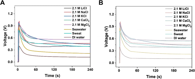 |
| | Fig. 5 Numerical simulation of the electrical performance of KB6/W-based HENGs with various salts of 2.1 M. Experimental (A) and simulated (B) real-time open-circuit voltages (VOC); A is reprinted with permission from,3 copyright 2023, Elsevier. | |
3.4 Properties of the nanomaterial
To improve the output power density of HENGs, single-layer MXenes were employed as the functional nanomaterials. Although SMX-based HENGs exhibited a high transient output power, the steady-state power was too low to be sufficient for long-term use. To improve the steady-state power, a carbon-based conductive material such as KB was used to improve the steady-state power. KB has good conductivity and can be employed individually in HENGs.3 While KB-based HENGs gave lower transit powers, the steady-state powers were higher than those from SMX-based HENGs. Thus, KB is an excellent candidate to incorporate with SMX to improve the steady-state power. The KB@SMX-based HENG was prepared by mixing 10 mg mL−1 KB ink and 23 mg mL−1 SMX (Fig. 6 and S6†). As the SMX content in the ink increased, the transient voltage and current of KB@SMX-based HENGs increased, but their steady voltage decreased significantly (Fig. 6A and B). In addition, fewer KB particles were shed. This indicates that the presence of SMX significantly improved the stability of KB on wool. Fig. 6 and S7† show that KB@SMX-based HENGs (1![[thin space (1/6-em)]](https://www.rsc.org/images/entities/char_2009.gif) :
:![[thin space (1/6-em)]](https://www.rsc.org/images/entities/char_2009.gif) 1) have the highest steady-state and transient-state output voltages. This is because SMX fills the dead space around the KB nanoparticles. Although KB@SMX-based HENGs (1
1) have the highest steady-state and transient-state output voltages. This is because SMX fills the dead space around the KB nanoparticles. Although KB@SMX-based HENGs (1![[thin space (1/6-em)]](https://www.rsc.org/images/entities/char_2009.gif) :
:![[thin space (1/6-em)]](https://www.rsc.org/images/entities/char_2009.gif) 0, 1
0, 1![[thin space (1/6-em)]](https://www.rsc.org/images/entities/char_2009.gif) :
:![[thin space (1/6-em)]](https://www.rsc.org/images/entities/char_2009.gif) 1, and 1
1, and 1![[thin space (1/6-em)]](https://www.rsc.org/images/entities/char_2009.gif) :
:![[thin space (1/6-em)]](https://www.rsc.org/images/entities/char_2009.gif) 2) have a higher voltage output both in the steady state and in the transient state, KB@SMX inks are difficult to apply in practical applications. KB nanoparticles precipitated when the amount of SMX was increased during the preparation of the solution. A possible reason is that SMX adsorbs CTAB, which affects the dispersion of KB in water.
2) have a higher voltage output both in the steady state and in the transient state, KB@SMX inks are difficult to apply in practical applications. KB nanoparticles precipitated when the amount of SMX was increased during the preparation of the solution. A possible reason is that SMX adsorbs CTAB, which affects the dispersion of KB in water.
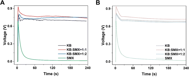 |
| | Fig. 6 Numerical simulation results of the electrical performance of KB@SMX-based HENGs with various ratios of KB![[thin space (1/6-em)]](https://www.rsc.org/images/entities/char_2009.gif) : :![[thin space (1/6-em)]](https://www.rsc.org/images/entities/char_2009.gif) SMX. Experimental (A) and simulated (B) real-time open-circuit voltages (VOC) (sweat was used). SMX. Experimental (A) and simulated (B) real-time open-circuit voltages (VOC) (sweat was used). | |
3.5 Relative humidity
Relative humidity has been previously found to have no significant impact on the electrical current.36 Our study also confirmed this by showing that RH has negligible effects on streaming potential output and solution velocity.7 The partial pressure of vapor in saturated air (pVA) is around 2310 Pa. The partial pressure of vapor in air  is a product of RH and the partial pressure of vapor in saturated air. The capillary pressure is higher than the ambient pressure (105 Pa). Thus, the pressure induced by a change in RH is much lower than the capillary pressure. This implies that electricity generation in HENGs is not mainly induced by evaporation, given that RH can significantly influence the evaporation process.36,37
4 Conclusion
To sum up, the electricity generation mechanism of HENGs was investigated by studying the streaming potential in the diffusion layer and surface potential in the stern layer, which was overlooked in previous studies. Through COMSOL Multiphysics, a new model was proposed using Darcy's Law, phase transfer in porous media, and current modules, using macroscopic methods to simulate electricity generation. The Robin-type boundary condition in this model accounted for the shortcomings of Neumann- and Dirichlet-type boundary conditions. This model is the first to simulate evaporation as a variable of streaming potential, while the streaming potential in previous studies was a steady flow. Based on streaming potential and EDL effects, the simulation calculations can be carried out based on actual water flow conditions, exploring the mechanism of hydroelectric electricity generation, while the calculation of streaming potentials in previous studies was based on the Helmholtz–Smoluchowski equation and required the provision of pressure difference conditions. The model was validated through our experimental studies showing the significant impact of surface functional groups, penetration, ion concentration, and ion types on HENGs' performance. The simulated results are consistent with the experimental data both qualitatively and quantitatively. In contrast, it has been shown that the relative humidity has a slight impact on electricity generation in HENGs. The model will pave the way to design and fabricate a new class of HENGs with enhanced performance and long-term stability. The versatility of the model to different active materials is worthy of exploration in the future, and apart from the materials, the influence of other factors such as porosity and pore size is also important to investigate.
Data availability
The data supporting this study are in the paper and the ESI† or available from the corresponding authors on reasonable request.
Author contributions
Hongli Su: conceptualization, investigation, characterization, simulation, writing – original draft preparation, figure edition. Azadeh Nilghaz: conceptualization, supervision, writing – reviewing & editing, funding acquisition. Kunning Tang: writing – reviewing & editing. Shuaifei Zhao: writing – reviewing & editing. Dan Liu: formal analysis. Junfei Tian: writing – reviewing & editing. Yiming Bu: writing – reviewing & editing. Jingliang Li: conceptualization, supervision, writing – reviewing & editing.
Conflicts of interest
There are no conflicts to declare.
Acknowledgements
AN would like to express her gratitude and deepest thanks to Deakin University for giving her financial support through the Alfred Deakin Research Fund. HL Su would like to express deepest thanks to image items by pikisuperstar, vector_corp, and motoviurii on freepik in abstract figure. HL Su thanks Jingfei Hong (University of Sheffield) for drawing abstract figures.
References
- H. Su,
et al., Harnessing the Power of Water: A Review of Hydroelectric Nanogenerators, Nano Energy, 2023, 116, 108819 CrossRef CAS.
- H. Su,
et al., Degradation of Phenolic Pollutants by Persulfate-Based Advanced Oxidation Processes: Metal and Carbon-Based Catalysis, Rev. Chem. Eng., 2023, 39(8), 1269 CrossRef CAS.
- H. Su,
et al., Self-Operating Seawater-Driven Electricity Nanogenerator for Continuous Energy Generation and Storage, Chem. Eng. J. Adv., 2023, 14, 100498 CrossRef CAS.
- A. Midilli, I. Dincer and M. Ay, Green Energy Strategies for Sustainable Development, Energy Policy, 2006, 34(18), 3623 CrossRef.
- Z. Liang,
et al., Next-Generation Energy Harvesting and Storage Technologies for Robots across All Scales, Adv. Intell. Syst., 2023, 5(4), 2200045 CrossRef.
- S. Chu and A. Majumdar, Opportunities and Challenges for a Sustainable Energy Future, Nature, 2012, 488(7411), 294 CrossRef CAS PubMed.
- H. Su,
et al., Efficient Energy Generation from a Sweat-Powered Wearable Mxene-Based Hydroelectric Nanogenerator, Device, 2024, 2(5), 100356 CrossRef.
- G. Xue,
et al., Water-Evaporation-Induced Electricity with Nanostructured Carbon Materials, Nat. Nanotechnol., 2017, 12(4), 317 CrossRef CAS PubMed.
- X. Li,
et al., A Green and Sustainable Water Evaporation-Induced Electricity Generator with Woody Biochar, Nano Energy, 2023, 112, 108491 CrossRef CAS.
- X. Zhao,
et al., Water-Enabled Electricity Generation: A Perspective, Adv. Energy Sustainability Res., 2022, 3(4), 2100196 CrossRef.
- L. Gong, J. K. Wu and B. Chen, Electrokinetic Flow and Measure Method in Microfluidic, Appl. Mech. Mater., 2013, 275, 649 Search PubMed.
- W. Olthuis,
et al., Energy from Streaming Current and Potential, Sens. Actuators, B, 2005, 111, 385 CrossRef.
- H. Ko,
et al., Why Does Water in Porous Carbon Generate Electricity? Electrokinetic Role of Protons in a Water Droplet-Induced Hydrovoltaic System of Hydrophilic Porous Carbon, J. Mater. Chem. A, 2023, 11(3), 1148 RSC.
- M. S. Kang,
et al., Understanding the Electrokinetic Role of Ions on Electricity Generation in Droplet-Based Hydrovoltaic Systems, J. Phys. Chem. C, 2023, 127(34), 16811 CrossRef CAS.
- J. Yin,
et al., Hydrovoltaic Energy on the Way, Joule, 2020, 4(9), 1852 CrossRef.
- P. Guan,
et al., Recent Development of Moisture-Enabled-Electric Nanogenerators, Small, 2022, 18(46), 2204603 CrossRef CAS PubMed.
- S. G. Yoon,
et al., Natural Evaporation-Driven Ionovoltaic Electricity Generation, ACS Appl. Electron. Mater., 2019, 1(9), 1746 CrossRef CAS.
- L. Wan,
et al., Self-Consistent Approach to Global Charge Neutrality in Electrokinetics: A Surface Potential Trap Model, Phys. Rev. X, 2014, 4(1), 011042 CAS.
- Z. Xu,
et al., Digital Flow Control of Electroosmotic Pump: Onsager Coefficients and Interfacial Parameters Determination, Solid State Commun., 2011, 151(6), 440 CrossRef CAS.
- S. H. Behrens and D. G. Grier, The Charge of Glass and Silica Surfaces, J. Chem. Phys., 2001, 115(14), 6716 CrossRef CAS.
- C. Gentil, D. Côte and U. Bockelmann, Transistor Based Study of the Electrolyte/SiO2 Interface, Phys. Status Solidi A, 2006, 203(14), 3412 CrossRef CAS.
- L. Wan and N.-H. Tong, Poisson–Boltzmann Equation with a Random Field for Charged Fluids, J. Phys.: Condens. Matter, 2019, 31(37), 375101 CrossRef CAS PubMed.
-
S. P. Venkateshan and P. Swaminathan, Computational Methods in Engineering, Elsevier Science, 2014, p. 536 Search PubMed.
- K. Tang,
et al., A Pore-Scale Model for Electrokinetic In Situ Recovery of Copper: The Influence of Mineral Occurrence, Zeta Potential, and Electric Potential, Transp. Porous Media, 2023, 150(3), 601 CrossRef CAS.
- R. H. Brooks and A. T. Corey, Properties of Porous Media Affecting Fluid Flow, J. Irrig. Drain. Div., 1966, 92(2), 61 CrossRef.
- Y. Qin,
et al., Constant Electricity Generation in Nanostructured Silicon by Evaporation-Driven Water Flow, Angew. Chem., Int. Ed., 2020, 132(26), 10706 CrossRef.
- Y. Li,
et al., Spontaneous and Sustainable Multifunctional Transpiration Generator for Simultaneous Harvesting of Electricity, Freshwater
and Salt, Appl. Energy, 2023, 341, 121110 CrossRef.
- M. A. Brown, A. Goel and Z. Abbas, Effect of Electrolyte Concentration on the Stern Layer Thickness at a Charged Interface, Angew. Chem., Int. Ed., 2016, 128(11), 3854 CrossRef.
- F. H. Van der Heyden,
et al., Electrokinetic Energy Conversion Efficiency in Nanofluidic Channels, Nano Lett., 2006, 6(10), 2232 CrossRef CAS PubMed.
- D. C. Grahame, The Electrical Double Layer and the Theory of Electrocapillarity, Chem. Rev., 1947, 41(3), 441 CrossRef CAS PubMed.
- Q. Gao,
et al., Tracking Ion Intercalation into Layered Ti3C2 Mxene Films across Length Scales, Energy Environ. Sci., 2020, 13(8), 2549 RSC.
- J. Veerman,
et al., Resistance of Ion Exchange Membranes in Aqueous Mixtures of Monovalent and Divalent Ions and the Effect on Reverse Electrodialysis, Membranes, 2023, 13(3), 322 CrossRef CAS PubMed.
- J. Veerman, Concepts and Misconceptions Concerning the Influence of Divalent Ions on the Performance of Reverse Electrodialysis Using Natural Waters, Membranes, 2023, 13(1), 69 CrossRef CAS PubMed.
- Ö. Tekinalp,
et al., Cation Exchange Membranes and Process Optimizations in Electrodialysis for Selective Metal Separation: A Review, Membranes, 2023, 13(6), 566 CrossRef PubMed.
- J. Bae,
et al., Towards Watt-Scale Hydroelectric Energy Harvesting by Ti3C2T X-Based Transpiration-Driven Electrokinetic Power Generators, Energy Environ. Sci., 2022, 15(1), 123 RSC.
- K. Ni,
et al., Ion Diode-Like Heterojunction for Improving Electricity Generation from Water Droplets by Capillary Infiltration, Adv. Mater., 2023, 35(40), 2305438 CrossRef CAS PubMed.
- L. Li,
et al., A Hydrovoltaic Power Generation System Based on Solar Thermal Conversion, Nano Energy, 2022, 99, 107356 CrossRef CAS.
|
| This journal is © The Royal Society of Chemistry 2024 |
Click here to see how this site uses Cookies. View our privacy policy here.  a,
Azadeh
Nilghaz
*ab,
Kunning
Tang
c,
Dan
Liu
a,
Shuaifei
Zhao
a,
Azadeh
Nilghaz
*ab,
Kunning
Tang
c,
Dan
Liu
a,
Shuaifei
Zhao
 a,
Junfei
Tian
 d,
Yiming
Bu
a and
Jingliang
Li
 *a
*a


![[thin space (1/6-em)]](https://www.rsc.org/images/entities/char_2009.gif) :
:![[thin space (1/6-em)]](https://www.rsc.org/images/entities/char_2009.gif) 1) have the highest steady-state and transient-state output voltages. This is because SMX fills the dead space around the KB nanoparticles. Although KB@SMX-based HENGs (1
1) have the highest steady-state and transient-state output voltages. This is because SMX fills the dead space around the KB nanoparticles. Although KB@SMX-based HENGs (1![[thin space (1/6-em)]](https://www.rsc.org/images/entities/char_2009.gif) :
:![[thin space (1/6-em)]](https://www.rsc.org/images/entities/char_2009.gif) 0, 1
0, 1![[thin space (1/6-em)]](https://www.rsc.org/images/entities/char_2009.gif) :
:![[thin space (1/6-em)]](https://www.rsc.org/images/entities/char_2009.gif) 1, and 1
1, and 1![[thin space (1/6-em)]](https://www.rsc.org/images/entities/char_2009.gif) :
:![[thin space (1/6-em)]](https://www.rsc.org/images/entities/char_2009.gif) 2) have a higher voltage output both in the steady state and in the transient state, KB@SMX inks are difficult to apply in practical applications. KB nanoparticles precipitated when the amount of SMX was increased during the preparation of the solution. A possible reason is that SMX adsorbs CTAB, which affects the dispersion of KB in water.
2) have a higher voltage output both in the steady state and in the transient state, KB@SMX inks are difficult to apply in practical applications. KB nanoparticles precipitated when the amount of SMX was increased during the preparation of the solution. A possible reason is that SMX adsorbs CTAB, which affects the dispersion of KB in water.
 is a product of RH and the partial pressure of vapor in saturated air. The capillary pressure is higher than the ambient pressure (105 Pa). Thus, the pressure induced by a change in RH is much lower than the capillary pressure. This implies that electricity generation in HENGs is not mainly induced by evaporation, given that RH can significantly influence the evaporation process.36,37


