 Open Access Article
Creative Commons Attribution 3.0 Unported Licence
Pt single atom alloyed sub-1 nm thick Fe overlayer on supported Cu nanoparticles for methylcyclohexane dehydrogenation†
Akira
Oda
 *a,
Kosei
Ichihashi
a,
Yuta
Yamamoto
b,
Takeshi
Ohtsu
a,
Wei
Shi
 a,
Kyoichi
Sawabe
a and
Atsushi
Satsuma
 a
a
aDepartment of Materials Chemistry, Graduate School of Engineering, Nagoya University, Furo-cho, Chikusa-ku, Nagoya, 464-8603, Japan. E-mail: akira@chembio.nagoya-u.ac.jp
bInstitute of Materials and Systems for Sustainability, Nagoya University, Nagoya, 464-8603, Japan
First published on 23rd July 2024
Abstract
There is an urgent need for the development of a precious metal-conserving catalyst having high activity, selectivity, and durability for methylcyclohexane (MCH) dehydrogenation, a significant aspect of hydrogen storage and transportation. A Pt-single atom alloyed Fe catalyst with sub-1 nm size is a good candidate for this purpose because of meeting site requirements for enhancement of activity, durability, selectivity, and utilization efficiency of Pt. However, this design is challenging due to the high surface energy of Fe. In this study, to break the limitation of catalyst design, we used a combination of two phenomena spontaneously taking place at the solid surface, i.e., (1) Fe dispersion on Cu, and (2) substitution of metallic Fe atoms with Pt cations. Here, we report a Pt single-atom alloyed sub-1 nm thick Fe overlayer on Cu nanoparticles. The Fe overlayer serves as the host metal to restrict Pt single atoms at the surface and provides an optimal coordination environment for MCH dehydrogenation. Furthermore, the sub-1 nm thick Fe overlayer features low crystallinity and superior decoking properties, which imparts product/coke poisoning resistance to the Pt single atom site, resulting in enhancements of both durability and activity. The H2-evolution rate per Pt mass was at least 133 times higher than that of state-of-the-art catalysts: Pt-based intermetallic compounds. This research demonstrates the significance of a single-atom-alloying approach with unique nanostructures specifically formed at the solid surface for the development of more efficient sustainable catalytic transformation processes.
1. Introduction
With the development of society, the consumption of fossil fuels has increased and environmental problems have become more serious.1 Hydrogen is a clean energy that can be utilized as a renewable energy source and has about three times the mass-specific energy of gasoline and a high energy conversion efficiency.2–4 The conversion from fossil fuels to hydrogen energy will contribute to the reduction of environmental impact, revitalization of industry, and disaster preparedness. However, hydrogen is in a gaseous state at room temperature and atmospheric pressure, and has extremely low volume specific energy, making storage and transportation difficult and problematic for safety. Therefore, the establishment of hydrogen storage and transportation technology is one of the challenges in the social use of hydrogen.Liquid organic hydrogen carriers (LOHC) are a technology for storing and transporting hydrogen by chemically bonding it to liquid organic compounds,5 allowing for the storage and transportation of hydrogen as if it were a liquid. In particular, toluene/methylcyclohexane (TOL/MCH) is considered a promising LOHC because of a high gravimetric and volumetric density of hydrogen (6.1 wt%, 47.0 kg-H2 per m3).6 Furthermore, it can be stored and transported using fossil fuel infrastructure, making it easy to handle as a LOHC for social uses.6–8 However, the hydrogen-releasing process, that is the dehydrogenation of MCH, is an endothermic reaction and generally requires external energy (temperatures of 300–400 °C). The development of efficient dehydrogenation catalysts is necessary for reducing energy costs.
It is well known that the active sites with more than one Pt atom (ensemble of Pt atoms) present at the surface of supported Pt nanoparticles have excellent properties to activate C–H bonds but poor properties to activate C–C bonds.9,10 Therefore, a considerable number of researchers focus on Pt-based materials for the development of MCH dehydrogenation catalysts.11–19 However, the ensemble of only Pt atoms exhibits a strong affinity for the aromatic ring and suffers product poisoning which increases the opportunity for side reactions between adsorbed TOLs and promotes coke deposition relevant to catalyst deactivation.6 Alloying a second metal with the supported Pt nanoparticles is a well-known modification procedure to improve both durability and activity.15,17,19–21 Alloying effects include the (1) dilution of the ensemble of Pt atoms, (2) electronic structure modifier to reduce affinity for TOL and (3) imparting coke poisoning resistance to the Pt ensemble.17 Nevertheless, it has yet to create catalytic performances that meet industrial demand. To reduce the cost of hydrogen carriers, it is important to develop catalysts with high activity, selectivity, durability, and Pt-utilization efficiency.22 For this purpose, chemistry related to heteroatom ensemble design should be further advanced.
One approach to maximize Pt utilization efficiency is to alloy Pt atomically on the base metal surface.23–25 Despite the atomic form, it has metallic properties with unique electronic states and local structures through interactions with the surface of base metals, generating highly active sites and developing challenging reaction mechanisms. It is called single-atom alloy (SAA) catalysts. In this paper, we use the term SAA as “lonely atoms alloyed to the surface of the host metal”. Pt SAA catalysts have been reported to exhibit remarkable performance in many catalytic reactions23–25 including dehydrogenation of light alkane.26 In spite of that, Pt SAA catalysts have not been applied to the MCH dehydrogenation reaction. It has been reported that the Fe sites of Pt–Fe alloys exhibit decoking properties and good durability in MCH dehydrogenation.17 Considering this, Pt–Fe SAA using Fe as a host metal is expected to create active sites (ensemble of a Pt single atom and few Fe atoms) having both superior durability and Pt utilization efficiency. In addition, based on the basic knowledge of the structure–activity relationship of Pt-based catalysts for alkane dehydrogenation, a dramatic improvement in activity can be expected by controlling the coordination environment of Pt SAA sites.26–28 As the disadvantage of the use of Fe as the host metal, the crystalline surface of Fe strongly interacts with the aromatic ring,29 which will lead to product poisoning in MCH dehydrogenation. Downsizing to sub-1 nm is a possible approach for the reduction of the crystallinity and improvement of performances in catalytic dehydrogenation;30,31 however, it is challenging for the design of Pt–Fe SAA due to the high surface energy of Fe.
Here, we report a Pt single atom alloyed sub-1 nm thick Fe overlayer grown on the supported Cu nanoparticles for MCH dehydrogenation. Our approach used the strong interactions between supported bimetal (Cu and Fe) for designing the ideal structure. It has been reported that a FeCu-based water–gas shift (WGS) catalyst produces a FeOx overlayer covering the Cu surface, where Cu acts as a support and stabilizes FeOx overlayers via strong metal support interaction (SMSI).32,33 By reduction of the supported FeCu bimetal and subsequent galvanic replacement with Pt atoms, we successfully developed the novel Pt–Fe SAA overlayer catalyst. The Fe overlayers restricted Pt single-atoms on the surface and provided an optimal coordination environment for the MCH dehydrogenation reaction, resulting in an extremely high H2 generation rate per Pt weight (22![[thin space (1/6-em)]](https://www.rsc.org/images/entities/char_2009.gif) 929 mmolH2 gPt−1 min−1), 133 times higher than that of state-of-the-art catalysts, i.e., Pt-based intermetallic compounds.17 The superior activity is maintained for a longer time than binary Pt–M SAAs (M = Cu and Fe) due to the homogeneous atomic size of strong Pt–Fe bonds capable of synergy between the atomic Pt (excellent dehydrogenation activity) and the low crystalline Fe surface (decoking properties and enhancement of TOL desorption).
929 mmolH2 gPt−1 min−1), 133 times higher than that of state-of-the-art catalysts, i.e., Pt-based intermetallic compounds.17 The superior activity is maintained for a longer time than binary Pt–M SAAs (M = Cu and Fe) due to the homogeneous atomic size of strong Pt–Fe bonds capable of synergy between the atomic Pt (excellent dehydrogenation activity) and the low crystalline Fe surface (decoking properties and enhancement of TOL desorption).
The purpose of this study is to demonstrate the significance of a single atom-alloying approach with the unique structure of the supported bimetal for creating substantially high activity, selectivity, durability, and Pt-utilization efficiency in MCH dehydrogenation. We first design a variety of binary Pt–MA SAA catalysts (MA = Cu, Fe, Zn, Co, Ni, Sn, Ga, Ag) and examine their catalytic performances. Given the superior performance of Pt–Fe SAA, we aim to further improve its functionality through the interaction with Cu; the research is extended to ternary Pt–FeCu SAA catalysts and proves their excellent activity and durability. In situ synchrotron Powder X-ray diffraction (PXRD), X-ray absorption fine structure (XAFS), Fourie transform infrared spectroscopy using CO as a probe molecule (CO-FTIR), X-ray photoelectron spectroscopy (XPS), transmission electron microscopy (TEM), and high-angle annular dark-field scanning transmission electron microscopy (HAADF-STEM) are used to identify the novel nanostructure, i.e., a Pt–Fe SAA-overlayer grown on Cu nanoparticles. The key properties in MCH dehydrogenation, i.e., TOL releasing property, coke deposition resistance, and hydrogen abstraction efficiency, of the designed Pt–Fe SAA-overlayer catalyst are evaluated by in situ Raman spectroscopy, temperature-programmed oxidation (TPO), TOL breakthrough curves, MCH temperature-programmed reaction (MCH-TPR), and kinetic experiments. Through comparison with binary Pt–Fe and Pt–Cu SAAs, we demonstrate the sub-1 nm thick Pt–Fe SAA overlayer grown on Cu nanoparticles is the ideal structure for catalyzing MCH dehydrogenation.
2. Results and discussion
2.1 Composition dependent catalytic performances of supported Pt-based SAA catalysts in MCH dehydrogenation
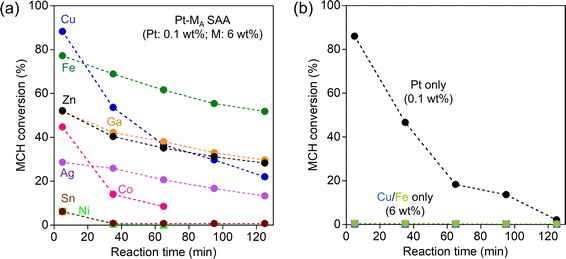
Fig. 1a shows the change in MCH dehydrogenation activity of Pt–MA SAA over time. The Pt–Cu SAA, known as a good dehydrogenation catalyst, displayed remarkable initial activity, achieving an 88.3% conversion at 5 min. However, its performance diminished rapidly within the 125 min reaction (22.0% at 125 min), indicating poor durability. Conversely, the Pt–Fe SAA exhibited moderate initial activity (77.2% at 5 min) and superior durability (51.8% at 125 min). The performance of other Pt–MA SAAs was notably inferior in terms of both initial activity and durability. Therefore, the choice of Fe as a host metal is crucial for enhancing both the activity and durability in methylcyclohexane (MCH) dehydrogenation.
To verify the impact of the Pt single-atom alloying approach, the activity of the catalysts loaded only with Pt, Fe, or Cu were also evaluated (Fig. 1b). Supported Pt showed initial activity similar to that of Pt–Cu SAA, but its deactivation was significant; the MCH conversion decreased from 86.0% to 2.1% during the 125 min reaction. No activity was observed for catalysts loaded only with Fe or Cu (<1% conversion). The activity comparison with Pt–MA SAAs shows that the Pt single atom alloying to the surface of the supported metal, especially Fe, is a good strategy for designing Pt-conserving catalysts with high activity and durability.
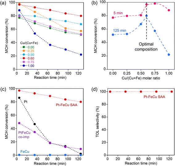
The activity of the ternary Pt–FeCu SAA catalysts was evaluated under the same conditions as for the binary Pt–MA SAA catalysts. The MCH dehydrogenation activity on the Pt–FeCu SAAs is shown in Fig. 2a. Time courses of concentrations of MCH and TOL are also shown in Fig. S2.† MCH dehydrogenation activity and durability were dependent on the Cu/(Cu + Fe) molar ratio. It is noteworthy that Pt–FeCu SAA showed higher initial activity and/or greater durability than binary Pt–MA SAAs. To quantify the composition dependence of the decay of the activity, the MCH conversions at 5 min and 125 min were compared as a function of the Cu/(Cu + Fe) molar ratio (Fig. 2b). Maxima activities were observed at Cu/Cu + Fe = 0.6 for both reaction times, suggesting the formation of the unique structure at this composition. On the other hand, neither high activity nor durability was observed for catalysts designed by simple co-impregnation of Pt, Fe, and Cu (PtFeCu-co-imp) or only base metals (FeCu), despite the similar compositions (Fig. 2c). Furthermore, other kinds of ternary Pt–MBCu SAA (MB = Ga, Zn, Sn) were not effective (Fig. S3†). These indicate that the alloying of Pt single atom on the surface of supported FeCu bimetal with a specific molar ratio is essential for creating high activity and durability. The Pt–FeCu SAA with the optimal Cu/(Cu + Fe) molar ratio had a TOL selectivity of almost 100%, making it useful for the desired hydrogen carrier application (Fig. 2d).
The Pt–FeCu SAA catalysts provided an exceptionally high H2 evolution rate per Pt mass (22![[thin space (1/6-em)]](https://www.rsc.org/images/entities/char_2009.gif) 929 mmolH2 gPt−1 min−1, responsible for turnover number frequency (TOF) of 4473 molH2 molPt−1 min−1) which 133-fold enhancement of the activity of the reported Pt3Fe0.75Zn0.25 intermetallic compound (171.8 mmolH2 gPt−1 min−1). Even if the H2 evolution rate of the Pt3Fe0.75Zn0.25 intermetallic compound is normalized with the surface Pt content, it is 757 mmolH2 gPt,surf−1 min−1, far from the activity of Pt–FeCu SAA, indicating that Pt–FeCu SAA possesses the unique heteroatom ensemble with higher activity. Due to the exceptionally high activity per weight of Pt, the H2 evolution rate per catalyst-weight is also remarkable (13.8 mmolH2 gcat−1 min−1) which is higher than that of Pt3Fe0.75Zn0.25 intermetallic compounds (5.2 mmol gcat−1 min−1), despite 2/100 less than Pt loading.17 Therefore, Pt–FeCu SAA is a noteworthy Pt-conserving catalyst for MCH dehydrogenation.
929 mmolH2 gPt−1 min−1, responsible for turnover number frequency (TOF) of 4473 molH2 molPt−1 min−1) which 133-fold enhancement of the activity of the reported Pt3Fe0.75Zn0.25 intermetallic compound (171.8 mmolH2 gPt−1 min−1). Even if the H2 evolution rate of the Pt3Fe0.75Zn0.25 intermetallic compound is normalized with the surface Pt content, it is 757 mmolH2 gPt,surf−1 min−1, far from the activity of Pt–FeCu SAA, indicating that Pt–FeCu SAA possesses the unique heteroatom ensemble with higher activity. Due to the exceptionally high activity per weight of Pt, the H2 evolution rate per catalyst-weight is also remarkable (13.8 mmolH2 gcat−1 min−1) which is higher than that of Pt3Fe0.75Zn0.25 intermetallic compounds (5.2 mmol gcat−1 min−1), despite 2/100 less than Pt loading.17 Therefore, Pt–FeCu SAA is a noteworthy Pt-conserving catalyst for MCH dehydrogenation.
2.2 Identification of structure of the best catalyst
We next identify the unique structure of Pt–FeCu SAA with an optimal composition of Cu/(Cu + Fe) = 0.6. In situ synchrotron-based PXRD of Pt–FeCu SAA catalysts with different Cu/(Cu + Fe) molar ratios are shown in Fig. 3a. In addition to diffraction lines attributed to the r-TiO2 support, fcc-Cu and bcc-Fe derived-diffraction lines were observed. Their strengths depended on the Cu/(Cu + Fe) molar ratio, as plotted in Fig. 3b. The fcc-Cu was dominant for Cu/(Cu + Fe) = 0.6, 0.75, and 1.0, while the bcc-Fe was dominant for Cu/(Cu + Fe) = 0.0, 0.25, and 0.33. Since the position of the diffraction lines of fcc-Cu and bcc-Fe were independent on the Cu/(Cu + Fe) molar ratios, the formation of binary fcc-FeCu alloy can be ruled out. The Pt–FeCu SAA with Cu/(Cu + Fe) = 0.6, where the best catalytic performance was observed, had the highest intensity of diffraction lines of fcc-Cu and negligible intensity of bcc-Fe. This indicates that the best catalysts include both a highly crystalline Cu and a less crystalline Fe species (e.g., highly dispersed state with size at sub-1 nm scale).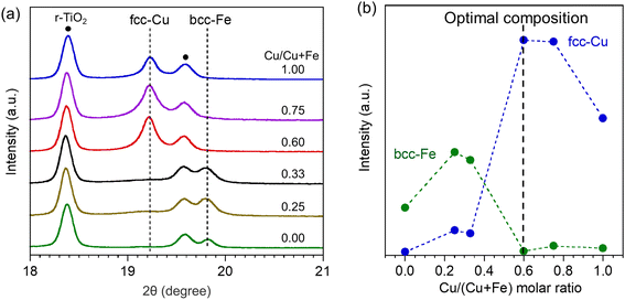 | ||
| Fig. 3 (a) Synchrotron-based PXRD patterns of Pt–FeCu SAA catalysts with different Cu/(Cu + Fe) molar ratios. (b) Plots of the diffraction line intensity of fcc-Cu and bcc-Fe against Cu/(Cu + Fe) molar ratio. Note that Pt–FeCu SAA with Cu/(Cu + Fe) = 0.0 and 1.0, i.e., Pt–Fe SAA and Pt–Cu SAA, were prepared with Fe/Cu loadings of 6 wt% each. On the other hand, for Cu/(Cu + Fe) = 0.25, 0.6, and 0.75, the total Fe/Cu content was adjusted to 12 wt% for the construction of bimetallic nanostructures (the actual loadings were determined by inductively coupled plasma emission spectrometry (ICP-AES) and summarized in Table S1†). Therefore, the supported Fe/Cu species aggregate more easily at Cu/(Cu + Fe) = 0.25–0.75, resulting in stronger diffraction lines attributed to bcc-Fe or fcc-Cu as compared with bimetallic systems (Cu/(Cu + Fe) = 0.0 and 1.0). | ||
The local structures of Pt, Cu, and Fe were characterized by XAFS spectroscopy. Fig. 4a and b show the Cu/Fe K-edge XANES spectra of Pt–FeCu SAA with Cu/(Cu + Fe) = 0.6. These spectra closely resemble those of Cu and Fe foils. Notably, the Fe K-edge XANES spectrum of Pt–FeCu SAA was significantly different from that of the Fe-containing alloy with a fcc crystal structure,35,36 ruling out the formation of fcc-FeCu alloy, consistent with the results of synchrotron-based PXRD. Linear combination fitting (LCF) of the experimental data indicated that 97.4% of the loaded Cu exists in the Cu0 state, while 72.6% of the loaded Fe exists in the Fe0 state (Fig. S5†).
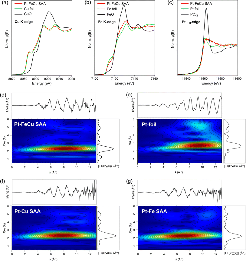 | ||
| Fig. 4 XANES spectra of Pt–FeCu SAA at (a) Cu K (b) Fe K, and (c) Pt LIII-edge. Pt LIII-edge WT-EXAFS of (d) Pt–FeCu SAA, (e) Pt foil, (f) Pt–Cu SAA, and (g) Pt–Fe SAA. | ||
Fig. 4c shows the Pt LIII-edge XANES spectrum of Pt–FeCu SAA. The spectral feature was unique to Pt SAA.34,37 The white line intensity was comparable to that of Pt-foil, indicating a near zero valence state of Pt constrained by the interactions with Fe/Cu atoms at the host bimetal. To demonstrate the Pt SAA, EXAFS functions were wavelet-transformed using a Morlet wavelet (κ = 15, σ = 1). This kind of analysis, called wavelet-transformed EXAFS (WT-EXAFS) allows us to picture whether Pt atoms interact with Cu/Fe or other Pt atoms. This is a powerful technique to identify the SAA catalysts.37 In Fig. 4d, WT-EXAFS of Pt–FeCu SAA is shown. The Pt–Fe/Cu bonds were directly detected for Pt–FeCu SAA. A lobe was observed at (R, k) = 2.2 Å and k = 7–8 Å−1. This is assignable to Pt–Fe/Cu backscattering based on the literature concerning structural analyses on Pt–M SAAs (M is 3d transition metals).34,37 Pt–Pt backscattering characteristic to higher R and k regions was not observed (compare with WT-EXAFS of Pt-foil shown in Fig. 4e), indicating that Pt single-atom sites are proved to be dominantly formed. SAA signature remained upon the activity test; thus, the Pt single atom sites are stable via strong interactions with Fe/Cu atoms (Fig. S6†). Furthermore, similar WT-EXAFS were observed also for binary Pt–Cu and Pt–Fe SAAs (Fig. 4f and g). Thus, all catalysts possess the Pt single atom sites. So far, there is no report concerning Pt–Fe SAA because of the design difficulty. We then computationally checked whether the Fe surface can stabilize Pt single atoms or not (ESI Discussion 3.1 and Fig. S7†). Our calculations revealed that the Fe surface provides an environment that stabilizes Pt in an atomic state and inhibits aggregation. Dealloying was thermodynamically unfavorable, and the SAA state was the most stable even when Pt single atoms bonded to each other.
CO-FTIR spectroscopy was employed to characterize the unique structures of the surface of Pt–FeCu SAA. This method has high surface sensitivity and, unlike bulk techniques (XAFS spectroscopy), provides information only on the surface. As demonstrated in the literature, coordination environments of the surface Pt single-atoms can be discussed based on CO-FTIR.26,37–39Fig. 5 shows the CO-FTIR spectrum of Pt–FeCu SAA. For comparison, the results of Pt–Cu SAA, Pt–Fe SAA, and FeCu are also given. The peak positions were determined by deconvolution of the spectra as summarized in Fig. S8–S10.† Pt–FeCu SAA gave mainly νCO bands at 2036 cm−1 and 1890 cm−1. The former is attributed to the CO species on top of Pt single atoms and the latter to the CO species on two-fold bridge sites.38,39 The similarities and differences in spectra are obvious when compared to Pt–Cu and Pt–Fe SAAs, representing the unique surface structure of the Pt–FeCu SAA (Fig. 5, schemes). First, the surface structure of the host metals is discussed. Most importantly, an atop band of Cu0–CO is observed for the Pt–Cu SAA at 2109 cm−1,38,39 but not for the Pt–FeCu SAA despite the higher Cu loading. This indicates a negligibly small fraction of the surface Cu0 species on Pt–FeCu SAA. Similar results have been observed for FeCu. These observations suggest that the surface of the supported Cu0 was covered by the Fe0 species (Fig. 5, scheme for Pt–FeCu SAA). A similar phenomenon was reported in the high-temperature WGS catalysts composed of Fe and Cu, where FeOx species is spontaneously dispersed on the Cu surface by strong interactions.32,33 In the present system, the higher-temperature reduction was performed in the catalyst preparation process; thus, the FeOx species is reduced to the Fe0 state as evidenced by Fe K-edge XAFS spectroscopy. In synchrotron-based PXRD, a bcc diffraction line was observed in Pt–Fe SAA, but not observed for Pt–FeCu SAA. A combination of synchrotron-based PXRD and CO-FTIR spectroscopy suggests that Fe0 is highly dispersed on Cu0 to the extent that it loses crystallinity.
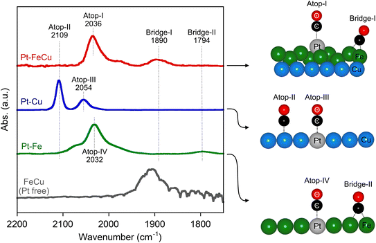 | ||
| Fig. 5 CO-FTIR spectra of Pt SAAs and FeCu. For comparison, the intensities of the spectra were normalized by the highest intensity. Proposed surface models upon the CO adsorptions are also given. | ||
The two-fold bridge band at 1890 cm−1 also offers insight into the characteristics of the low-crystalline Fe0 species specifically formed in Pt–FeCu SAA. In the literature, it has been shown that an ultrathin Fe layer on Cu(100) or Cu(111)40–42 and a Pt–Fe carbonyl complex with a cluster size43,44 have been shown to give a νCO band at around 1900 cm−1, near the measurement temperature applied in this study, which is closely similar to that observed in Pt–FeCu SAA. A similar band was observed also for FeCu; therefore, the 1890 cm−1 band is assigned to the two-fold bridged CO species on the Fe0 species highly dispersed on Cu. On the other hand, Pt–Fe SAA provided a two-fold bridge band at 1794 cm−1. A notable energy difference between Pt–FeCu SAA (1890 cm−1) and Pt–Fe SAA (1794 cm−1) suggests the difference in their surface structures. Considering the synchrotron-based PXRD data, the 1794 cm−1 band is assigned to the two-fold bridge CO species adsorbed on the surface of crystalline bcc-Fe.
We now turn to a discussion of the atop site-derived bands that give information about the local structures of Pt single-atom sites: 2100–2000 cm−1 regions. The νCO of the atop CO species in Pt–Cu SAA (2054 cm−1) was 18 cm−1 higher than that of Pt–FeCu (2036 cm−1), which evidences a different local structure of Pt single atom. On the other hand, the atop peak positions for Pt–FeCu SAA and Pt–Fe SAA were closely similar. The order of νCO was Pt–Fe SAA (2032 cm−1) ≈ Pt–FeCu SAA (2036 cm−1) < Pt–Cu SAA (2054 cm−1). This indicates that Pt–FeCu SAA creates the Pt single-atom site using surface Fe as a host metal, which is not inconsistent with the proposed model (Fig. 5, scheme for Pt–FeCu SAA). Due to the negligible contribution of the spectral feature of Pt–Cu SAA to the CO-FTIR spectrum of Pt–FeCu SAA, we can reasonably claim that the fraction of Pt atoms interacting with the Cu surface is negligibly small. Slightly higher νCO of Pt–FeCu SAA than that of Pt–Fe SAA indicates the different coordination environments of the Pt single atoms (vide infra).
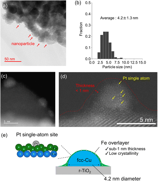
Direct observations with microscopy were carried out for Pt–FeCu SAA to confirm the novel structures. Fig. 6a shows in situ TEM images of the Pt–FeCu SAA catalyst (additional images are shown in Fig. S11†). Nanoparticles were observed on the r-TiO2 support. The average particle size was estimated as 4.2 ± 1.3 nm (Fig. 6b). When the nanoparticle was magnified by HAADF-STEM, bright spots were observed; these are Pt single atoms (Fig. 6c and d, additional images are shown in Fig. S12–S13†). This observation is consistent with the results of WT-EXAFS and CO-FTIR (Fig. 4 and 5) and literature findings.26,37 The lattice spacing of the nanoparticles was 0.21 nm (Fig. S14b,† regions i and ii), which is in good agreement with that of Cu(111);26,37 thus, the nanoparticles can be assigned to fcc-Cu nanoparticles. Furthermore, a thin layer was observed on the fcc-Cu nanoparticles (Fig. 6d, red dot line). The thickness was in a sub-1 nm scale; refer to the line scan profiles shown in Fig. S14a,† regions i–iii. Unfortunately, the nanostructures are extremely sensitive to electron beams, leading to their immediate disintegration during observation, thus preventing visualization of elemental distribution via energy-dispersive X-ray and electron energy-loss spectroscopy. However, combined with the results of in situ synchrotron PXRD, XAFS, and CO-FTIR, the thin layer is reasonably assigned to the low-crystalline Fe overlayer grown on the Cu nanoparticles. One may argue that there are other possibilities for the assignment. For example, the TiOx layer-derived from the strong metal support interaction45 or Cu layer can be considered (Fig. S15†). However, these possibilities can be excluded from the considerations based on the CO-FTIR results (refer to ESI Discussion 3.2†). Furthermore, we can see that the thin layer spreads also over the surface of the r-TiO2 support. The presence of such a wet structure can be clearly seen in the line scan profile shown in Fig. S14b,† region iii. Consistently, the Fe K-edge XANES spectrum showed the formation of positively charged Fe via the electron transfer interaction between the spread Fe overlayer and r-TiO2 surface (Fig. S5†). The fraction of the oxide forms was more prominent for Pt–Fe SAA because of the absence of the supported metallic Cu nanoparticles essential for the stabilization of the metallic Fe0 (refer to Fig. S16 and S17†).
To further support the unique structure, i.e., sub-1 nm thick Fe overlayer grown on Cu nanoparticles, surface atomic ratios of Fe and Cu were quantified by XPS which is sensitive to the surface depth of 2–3 nm (Fig. S18 and Table S2†). The surface Cu/(Cu + Fe) molar ratio was estimated as 0.52 which was smaller than the theoretical ratio estimated from the contents of Fe and Cu in catalyst preparation (0.6) and the experimental ratio determined by ICP-AES (0.64). This indicates that not all the Cu atoms were detected by XPS because of the diameter larger than 4 nm of the supported Cu nanoparticles. On the other hand, all Fe atoms would be detected due to the unique structure: Fe overlayer with a sub-1 nm thickness. Therefore, it is reasonable that a value smaller than the theoretical Cu/(Cu + Fe) molar ratios was estimated by XPS. Accordingly, a new class of Pt SAA catalyst, i.e., Pt single atom alloyed sub-1 nm thick Fe overlayer grown on the supported Cu nanoparticles was identified experimentally (Fig. 6e).
2.3 Origin of the exceptionally high catalytic performances of sub-1 nm thick Pt–Fe SAA overlayer grown on Cu nanoparticles
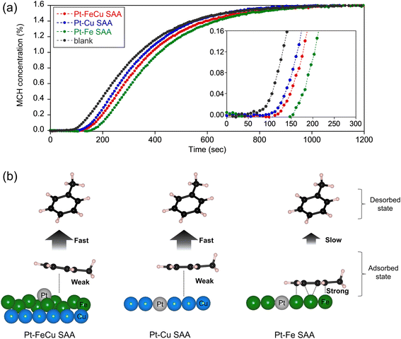
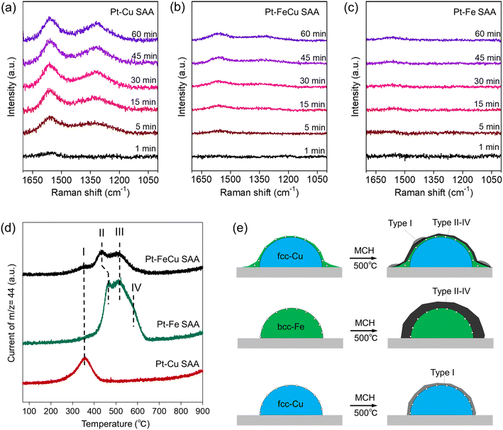
Structure–function relationships of supported Pt catalysts in MCH dehydrogenation reaction have been investigated so far.17,19 The key structural factors that create high activity and durability are related to an ensemble of surface metal atoms, because it determines the efficiencies of product poisoning, coke formation, and hydrogen abstraction from MCH. In this section, we address the origin of the remarkable catalytic performances of Pt–FeCu SAA based on the experiments that allow the evaluation of the above important properties of the heteroatom ensemble specifically formed at the Pt–Fe SAA overlayer.To further correlate the catalyst surface structure with coke deposition behavior, each SAA catalyst was reacted with MCH at a higher temperature (500 °C) to intentionally deposit coke, and the catalysts were calcined under oxygen. The CO2 formed in the combustion of the cokes was tracked by on-line mass spectroscopy along the calcination temperatures, and TPO spectra were obtained (Fig. 8d). The difference in the temperature required for the combustion of the cokes was observed among Pt–FeCu, Pt–Fe, and Pt–Cu SAAs. Pt–Cu SAA gave only one peak in the 300–400 °C range (band I). Pt–FeCu and Pt–Fe SAAs gave four peaks in the 300–650 °C range (bands I–IV). It is well known that TPO spectral features are dependent on the surface composition of the supported metal and the type of support, although the mechanism is under debate.47 The observation of similarity in TPO spectra of Pt–FeCu and Pt–Fe SAAs is reasonable by consideration of the proposed models with Fe-enriched surfaces. However, a difference was also observed; that is, the amount of coke deposited in Pt–FeCu SAA was substantially lower than in Pt–Fe SAA. The surface-structure-dependent coke-deposition phenomena were schematically described in Fig. 8e. The obtained results mean that the low crystalline Pt–Fe SAA layer has superior resistance to coke-deposition than crystalline Pt–Fe SAA with the bcc crystal structure. One possible factor is the difference in the fraction of Fe ensembles that are effective in the fixation and activation of TOLs. This ensemble effect contributes to the increase in the rate of side-reaction of TOL, i.e., condensation reactions with the coke deposition. Accordingly, the sub-1 nm thick Fe0 layer on the Cu nanoparticles promoted TOL desorption and reduced the coke deposition rate, resulting in superior durability.
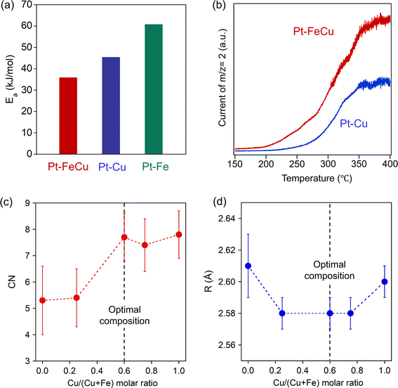
The coordination environments of the Pt site, e.g. neighboring elements, coordination number, and bond length, have a massive influence on the stability of the reaction intermediates and thereby strongly related to the hydrogen abstraction activity.26–28 In this study, we have designed highly active Pt single-atom sites using sub-1 nm thick Fe overlayer as a host metal; thus, its coordination environment should be unique. To substantiate it, curve fittings were carried out for the EXAFS functions attributed to the Pt–Fe/Cu backscattering observed on a series of Pt–FeCu SAA catalysts (Fig. S19, S20 and Table S3†). The obtained EXAFS parameters (Pt–Fe/Cu coordination number (CN) and distance (R)) are plotted against the Cu/(Cu + Fe) molar ratio in Fig. 9c and d. The CN increased with the increase in the Cu/(Cu + Fe) molar ratio, reaching 7.7 almost equivalent to that of Pt–Cu SAA but higher than Pt–Fe SAA. On the other hand, R was 2.58 Å in a range of Cu/(Cu + Fe) molar ratio of 0.25–0.75, which was shorter than Pt–Fe and Pt–Cu SAAs by 0.02–0.03 Å. Therefore, the Pt–FeCu SAA with the optimal composition possesses shorter Pt–Fe bonds with higher coordination numbers; it is a unique coordination environment among Pt-based SAAs. Pt LIII-edge XANES spectra showed near zero valence state of Pt in all catalysts (Fig. S21†). Taking account of the highest hydrogen abstraction activity, it was suggested that the Fe overlayer restricts Pt0 single atoms at the surface and provides an optimal coordination environment for MCH dehydrogenation.
3. Conclusions
In this study, we have successfully designed a novel Pt–Fe SAA overlayer with sub-1 nm thickness on the supported fcc-Cu nanoparticles and established the structure–function relationship in MCH dehydrogenation. The sub-1 nm thick Fe overlayer features low crystallinity and superior decoking properties, which imparts product/coke poisoning resistance to the Pt single atom site, resulting in enhancements of both durability and activity. The finely optimized local structure of the Pt single-atom site enables dehydrogenation with an H2-evolution rate per Pt-weight approximately 133 times higher than previously reported state-of-the-art catalysts, i.e., Pt-based intermetallic compounds.17 The findings of this study provide a new direction for the development of precious metal-conserving catalysts that contribute to the reduction of the cost of the catalytic applications relevant to hydrogen storage and transportation.SAA catalysts have high potential in a wide range of catalytic applications.23–25 Developments of strategy to rationally design SAAs with novel geometric/electronic structures will contribute to accelerating the discovery of exceptionally high catalytic performances while substantially reducing the number of precious metals required for catalysis. However, the existing strategy of designing SAA catalysts utilizes one kind of host metal, limiting the design flexibility. On the other hand, this study demonstrates not only the coordination environment of the single atoms but also the crystallinity, dispersibility, and morphology of the host metal can be further controlled by expanding from binary to ternary SAA systems. In other words, the unique nanostructures, which self-organize through strong interactions between the supported metals, can be used as the host metal to design unprecedented structures of SAA. Since the mechanism of interaction between supported metals depends on diverse parameters, the design flexibility of multi-element host metals is extremely high.51–53 Utilizing the unique self-organized metal nanostructures will expand the exploration space of SAA catalysts and develop more efficient sustainable catalytic transformation processes. This research outcome lays the foundation for further progress in this area.
Data availability
All data supporting this article have been included in the main text and the ESI.†Author contributions
A. O. supervised the project, performed XAFS, analyzed experimental data, and wrote the manuscript. K. I., T. O., and W. S. performed catalyst preparation, CO-FTIR, XAFS, and activity tests. Y. Y. performed HAADF-STEM and in situ TEM. In preparation of manuscript, all authors contributed to the discussions.Conflicts of interest
There are no conflicts to declare.Acknowledgements
This work was supported by the DAIKO FOUNDATION, ENEOS Hydrogen Trust Fund and Japan Society for the Promotion of Science (JSPS) Grant-in-Aid for Scientific Research (B) (No. 22H01866 and No. 23H01759) and JSPS Grant-in-Aid for Transformative Research Areas (B) (No. 22H05045). XAFS and PXRD measurements were performed at the synchrotron radiation facilities of the Aichi synchrotron radiation center.References
- N. S. Lewis and D. G. Nocera, Proc. Natl. Acad. Sci. U. S. A., 2006, 103, 15729–15735 CrossRef CAS PubMed.
- J. A. Turner, Science, 2004, 305, 972–974 CrossRef CAS PubMed.
- M. Z. Jacobson, W. Colella and D. Golden, Science, 2005, 308, 1901–1905 CrossRef CAS PubMed.
- J. Zhu, L. Hu, P. Zhao, L. Y. S. Lee and K.-Y. Wong, Chem. Rev., 2019, 120, 851–918 CrossRef PubMed.
- D. Teichmann, W. Arlt, P. Wasserscheid and R. Freymann, Energy Environ. Sci., 2011, 4, 2767–2773 RSC.
- F. Alhumaidan, D. Cresswell and A. Garforth, Energy Fuels, 2011, 25, 4217–4234 CrossRef CAS.
- Y. Okada, E. Sasaki, E. Watanabe, S. Hyodo and H. Nishijima, Int. J. Hydrogen Energy, 2006, 31, 1348–1356 CrossRef CAS.
- R. Atsumi, X. Cui, H. Matsumoto, K. Kobayashi, K. Matsuda, T. Tsujimura and T. Nanba, J. Jpn. Pet. Inst., 2019, 62, 28–36 CrossRef CAS.
- J. J. Sattler, J. Ruiz-Martinez, E. Santillan-Jimenez and B. M. Weckhuysen, Chem. Rev., 2014, 114, 10613–10653 CrossRef CAS PubMed.
- O. O. James, S. Mandal, N. Alele, B. Chowdhury and S. Maity, Fuel Process. Technol., 2016, 149, 239–255 CrossRef CAS.
- C. Zhang, X. Liang and S. Liu, Int. J. Hydrogen Energy, 2011, 36, 8902–8907 CrossRef CAS.
- S. Nagatake, T. Higo, S. Ogo, Y. Sugiura, R. Watanabe, C. Fukuhara and Y. Sekine, Catal. Lett., 2016, 146, 54–60 CrossRef CAS.
- A. Nakano, S. Manabe, T. Higo, H. Seki, S. Nagatake, T. Yabe, S. Ogo, T. Nagatsuka, Y. Sugiura and H. Iki, Appl. Catal., A, 2017, 543, 75–81 CrossRef CAS.
- J. Yan, W. Wang, L. Miao, K. Wu, G. Chen, Y. Huang and Y. Yang, Int. J. Hydrogen Energy, 2018, 43, 9343–9352 CrossRef CAS.
- K. Mori, Y. Kanda and Y. Uemichi, J. Jpn. Pet. Inst., 2018, 61, 350–356 CrossRef CAS.
- W. Wang, L. Miao, K. Wu, G. Chen, Y. Huang and Y. Yang, Int. J. Hydrogen Energy, 2019, 44, 2918–2925 CrossRef CAS.
- Y. Nakaya, M. Miyazaki, S. Yamazoe, K.-i. Shimizu and S. Furukawa, ACS Catal., 2020, 10, 5163–5172 CrossRef CAS.
- X. Zhang, N. He, L. Lin, Q. Zhu, G. Wang and H. Guo, Catal. Sci. Technol., 2020, 10, 1171–1181 RSC.
- K. Murata, N. Kurimoto, Y. Yamamoto, A. Oda, J. Ohyama and A. Satsuma, ACS Appl. Nano Mater., 2021, 4, 4532–4541 CrossRef CAS.
- A. Fung, M. Kelley, D. Koningsberger and B. Gates, J. Am. Chem. Soc., 1997, 119, 5877–5887 CrossRef CAS.
- J. J. Sattler, A. M. Beale and B. M. Weckhuysen, Phys. Chem. Chem. Phys., 2013, 15, 12095–12103 RSC.
- J. Meng, F. Zhou, H. Ma, X. Yuan, Y. Wang and J. Zhang, Top. Catal., 2021, 64, 509–520 CrossRef CAS.
- G. Giannakakis, M. Flytzani-Stephanopoulos and E. C. H. Sykes, Acc. Chem. Res., 2018, 52, 237–247 CrossRef PubMed.
- R. T. Hannagan, G. Giannakakis, M. Flytzani-Stephanopoulos and E. C. H. Sykes, Chem. Rev., 2020, 120, 12044–12088 CrossRef CAS PubMed.
- T. Zhang, A. G. Walsh, J. Yu and P. Zhang, Chem. Soc. Rev., 2021, 50, 569–588 RSC.
- G. Sun, Z.-J. Zhao, R. Mu, S. Zha, L. Li, S. Chen, K. Zang, J. Luo, Z. Li and S. C. Purdy, Nat. Commun., 2018, 9, 4454 CrossRef PubMed.
- X. Chen, M. Peng, X. Cai, Y. Chen, Z. Jia, Y. Deng, B. Mei, Z. Jiang, D. Xiao and X. Wen, Nat. Commun., 2021, 12, 2664 CrossRef CAS PubMed.
- Y. Deng, Y. Guo, Z. Jia, J.-C. Liu, J. Guo, X. Cai, C. Dong, M. Wang, C. Li and J. Diao, J. Am. Chem. Soc., 2022, 144, 3535–3542 CrossRef CAS PubMed.
- A. J. Hensley, R. Zhang, Y. Wang and J.-S. McEwen, J. Phys. Chem. C, 2013, 117, 24317–24328 CrossRef CAS.
- Q. Sun, N. Wang, Q. Fan, L. Zeng, A. Mayoral, S. Miao, R. Yang, Z. Jiang, W. Zhou and J. Zhang, Angew. Chem., Int. Ed., 2020, 59, 19450–19459 CrossRef CAS PubMed.
- X. Chen, M. Peng, D. Xiao, H. Liu and D. Ma, ACS Catal., 2022, 12, 12720–12743 CrossRef CAS.
- M. Zhu, T. C. Rocha, T. Lunkenbein, A. Knop-Gericke, R. Schlögl and I. E. Wachs, ACS Catal., 2016, 6, 4455–4464 CrossRef CAS.
- M. Zhu, P. Tian, R. Kurtz, T. Lunkenbein, J. Xu, R. Schlögl, I. E. Wachs and Y. F. Han, Angew. Chem., Int. Ed., 2019, 58, 9083–9087 CrossRef CAS PubMed.
- A. Oda, T. Fujita, Y. Yamamoto, K. Sawabe and A. Satsuma, ACS Catal., 2023, 13, 10026–10040 CrossRef CAS.
- P. Schilling, J. He, R. Tittsworth and E. Ma, Acta Mater., 1999, 47, 2525–2537 CrossRef CAS.
- T. Hirakawa, Y. Shimokawa, W. Tokuzumi, T. Sato, M. Tsushida, H. Yoshida, J. Ohyama and M. Machida, ACS Appl. Nano Mater., 2020, 3, 9097–9107 CrossRef CAS.
- X. Zhang, G. Cui, H. Feng, L. Chen, H. Wang, B. Wang, X. Zhang, L. Zheng, S. Hong and M. Wei, Nat. Commun., 2019, 10, 5812 CrossRef CAS PubMed.
- D. L. Molina, M. Inagaki, E. Kazuma, Y. Kim and M. Trenary, J. Phys. Chem. C, 2023, 127, 9796–9806 CrossRef CAS.
- A. Mohammadpour and S. Kaya, J. Phys. Chem. C, 2024, 128, 5480–5489 CrossRef CAS.
- T. Tanabe, Y. Suzuki, T. Wadayama and A. Hatta, Surf. Sci., 1999, 427, 414–418 CrossRef.
- T. Tanabe, R. Buckmaster, T. Ishibashi, T. Wadayama and A. Hatta, Surf. Sci., 2001, 472, 1–8 CrossRef CAS.
- T. Wadayama, K. Kubo, T. Yamashita, T. Tanabe and A. Hatta, Appl. Surf. Sci., 2002, 199, 254–258 CrossRef CAS.
- A. Siani, B. Captain, O. S. Alexeev, E. Stafyla, A. B. Hungria, P. A. Midgley, J. M. Thomas, R. D. Adams and M. D. Amiridis, Langmuir, 2006, 22, 5160–5167 CrossRef CAS PubMed.
- A. Siani, O. S. Alexeev, B. Captain, G. Lafaye, P. Marécot, R. D. Adams and M. D. Amiridis, J. Catal., 2008, 255, 162–179 CrossRef CAS.
- S. Zhang, P. N. Plessow, J. J. Willis, S. Dai, M. Xu, G. W. Graham, M. Cargnello, F. Abild-Pedersen and X. Pan, Nano Lett., 2016, 16, 4528–4534 CrossRef CAS PubMed.
- A. Sadezky, H. Muckenhuber, H. Grothe, R. Niessner and U. Pöschl, Carbon, 2005, 43, 1731–1742 CrossRef CAS.
- Z. Lian, C. Si, F. Jan, S. Zhi and B. Li, ACS Catal., 2021, 11, 9279–9292 CrossRef CAS.
- W. Zhao, C. Chizallet, P. Sautet and P. Raybaud, J. Catal., 2019, 370, 118–129 CrossRef CAS.
- C. Mi, Y. Huang, F. Chen, K. Wu, W. Wang and Y. Yang, Int. J. Hydrogen Energy, 2021, 46, 875–885 CrossRef CAS.
- X. Liu, X. Wang, S. Zhen, G. Sun, C. Pei, Z.-J. Zhao and J. Gong, Chem. Sci., 2022, 13, 9537–9543 RSC.
- X. Jiang, X. Nie, X. Guo, C. Song and J. G. Chen, Chem. Rev., 2020, 120, 7984–8034 CrossRef CAS PubMed.
- Y. Nakaya and S. Furukawa, Chem. Rev., 2022, 123, 5859–5947 CrossRef PubMed.
- L. Liu and A. Corma, Chem. Rev., 2023, 123, 4855–4933 CrossRef CAS PubMed.
Footnote |
| † Electronic supplementary information (ESI) available. See DOI: https://doi.org/10.1039/d4ta03453h |
| This journal is © The Royal Society of Chemistry 2024 |

