
 Open Access Article
 This Open Access Article is licensed under a
 Creative Commons Attribution 3.0 Unported Licence
In situ synthesis of cobalt-embedded gadolinia-doped ceria nanocatalysts for high-temperature solid oxide cells†
Hagyeong
Cho‡
ab,
Haewon
Seo‡
 a,
Jihong
Min
ab,
Ji-eun
Won
ab,
Jongsup
Hong
*b and
Kyung Joong
Yoon
*a
a,
Jihong
Min
ab,
Ji-eun
Won
ab,
Jongsup
Hong
*b and
Kyung Joong
Yoon
*a
aCenter for Energy Materials Research, Korea Institute of Science and Technology, 5, Hwarang-ro 14-gil, Seongbuk-gu, Seoul 02792, Republic of Korea. E-mail: kjyoon@kist.re.kr
bSchool of Mechanical Engineering, Yonsei University, 50, Yonsei-ro, Seodaemun-gu, Seoul 03722, Republic of Korea. E-mail: jongsup.hong@yonsei.ac.kr
First published on 3rd October 2024
Abstract
High-temperature solid oxide cells (SOCs) provide a highly efficient route for power generation and hydrogen production. In this study, we develop cobalt-embedded gadolinia-doped ceria nanocatalysts that significantly enhance the performance of nickel-based fuel electrodes of SOCs. These nanocatalysts are synthesized in situ within the pores of the electrode using a urea-based infiltration process. Doping gadolinia into the ceria lattice improves the oxygen ionic conductivity, and uniform gadolinia-doped ceria nanoparticles, 20–30 nm in size, consistently form within both symmetric and full cells. Meanwhile, a portion of the cobalt also forms discrete nanoparticles, less than 10 nm in size, further boosting catalytic activity. The electrochemical performance of the full cells is improved by approximately 30% and 60% in fuel cell and electrolysis mode operations, respectively. Additionally, the cell operates stably for 300 h under a constant electrolysis current of −1.0 A cm−2 at 700 °C, demonstrating that the nanocatalysts remain stable under harsh high-temperature conditions.
Introduction
Solid oxide cell (SOC) technology is considered a vital component of future energy systems because of its unique advantages associated with high operating temperatures.1,2 The term SOC jointly refers to solid oxide fuel cells (SOFCs) and solid oxide electrolysis cells (SOECs), meaning that SOCs can operate reversibly for both power generation and hydrogen production. SOCs use an oxygen-ion-conducting ceramic membrane as the electrolyte and typically operate above 700 °C, providing exceptionally high energy conversion efficiency and operational versatility. Since SOCs entered the market, their commercial feasibility has been successfully demonstrated, and their market share has rapidly increased in recent years.3,4 However, further improvements in performance and stability are still required for the widespread adoption of SOC technology.Traditionally, it was believed that the overall performance of SOCs was dominated by the air electrode because the ceramic materials used for this component are less catalytically active and have lower electrical conductivity than the metallic Ni used for the fuel electrode.5 Consequently, research efforts primarily focused on improving the air electrode, leading to significant advancements.6–15 These improvements to the air electrode also increased the fuel electrode's contribution to overall performance, providing an impetus for more recent efforts to enhance the fuel electrode performance.16 Unfortunately, modifying Ni-based fuel electrodes, especially in fuel-electrode-supported cells, has proven challenging. Fuel-electrode-supported cells offer higher performance than electrolyte-supported cells owing to their thin electrolyte. However, during fabrication, the fuel electrode is co-sintered with the electrolyte at high temperatures, typically above 1400 °C,17–22 restricting material choices to Ni and a few others because of chemical compatibility issues with the yttria-stabilized zirconia (YSZ) electrolyte.
One of the most practical and effective methods for modifying the properties of fuel electrodes is the infiltration of nanocatalysts. In infiltration process, a precursor solution is injected into the pores of the pre-sintered electrode, followed by thermal treatment to form nanocatalysts. However, controlling the infiltration process is challenging owing to the difficulty in managing the migration behavior of the liquid. In our earlier work, we developed a urea-based infiltration technique, where urea serves both as a complexing agent and a precipitation agent.6 As a complexing agent, urea provides two coordination sites—one carbonyl oxygen and two amide nitrogen atoms—ensuring a strong complexing effect that prevents phase separation during the drying process. As a precipitation agent, urea decomposes thermally at around 80 °C, leading to the homogeneous precipitation of the constituent elements while releasing ammonia and carbon dioxide. This dual role enables the formation of phase-pure nanocatalysts with uniform size and distribution.
Ceria-based materials are known as effective catalysts for the fuel electrode,23 and partially substituting cerium with gadolinium introduces additional oxygen vacancies, further promoting oxygen exchange kinetics.24 In previous studies, the infiltration of ceria-based nanocatalysts has demonstrated improvements in both performance and stability.25–28 Cobalt nanoparticles also increase the catalytic activity of the fuel electrode.29
In this study, we infiltrated cobalt-embedded ceria nanocatalysts into Ni-based fuel electrodes to improve its performance while avoiding chemical compatibility issues. Highly active nanocatalysts were synthesized on the inner surface of the pores of the standard Ni–YSZ fuel electrode, greatly improving performance in both fuel cell and electrolysis modes. The thermal stability of these nanomaterials was also evaluated by long-term testing under harsh electrolysis conditions.
Experimental
The precursor solutions for infiltration were prepared by dissolving Ce(NO3)3·6H2O (Merck KGaA, Germany), Gd(NO3)3·6H2O (Merck KGaA), and Co(NO3)2·6H2O (Merck KGaA) in a mixture of purified water and ethanol at a ratio of 25![[thin space (1/6-em)]](https://www.rsc.org/images/entities/char_2009.gif) :75 vol%. The precursors were mixed in the stoichiometric ratio specified for each Co content, and urea (Merck KGaA) was added to the solution at a urea-to-cation ratio of 10:1.6,30,31 Powder samples were produced by heat treating the solution at 80 °C for 1 h, followed by a further heat treatment at 700 °C for 1 h in air. Then, the powders were reduced in 5% H2 balanced with N2 at 700 °C for 1 h and analyzed using X-ray diffraction (XRD; D8 Advance, Bruker Corp., USA) and transmission electron microscopy (TEM; Titan 80-300, FEI Company, USA).
:75 vol%. The precursors were mixed in the stoichiometric ratio specified for each Co content, and urea (Merck KGaA) was added to the solution at a urea-to-cation ratio of 10:1.6,30,31 Powder samples were produced by heat treating the solution at 80 °C for 1 h, followed by a further heat treatment at 700 °C for 1 h in air. Then, the powders were reduced in 5% H2 balanced with N2 at 700 °C for 1 h and analyzed using X-ray diffraction (XRD; D8 Advance, Bruker Corp., USA) and transmission electron microscopy (TEM; Titan 80-300, FEI Company, USA).
Symmetric cells were fabricated using a 3 mm-thick dense YSZ substrate. To prepare the pastes for the Ni–YSZ functional layer and the Ni current collecting layer, NiO (Sumitomo Metal Mining Co., Ltd, Japan) and (Y2O3)0.08(ZrO2)0.92 (8YSZ) (TZ-8Y, Tosoh Corp.) powders (NiO/8YSZ = 66:34 wt%) were mixed with a dispersant (Hypermer KD15, Croda International plc, UK) and binder (ethyl cellulose (45 cP), Kanto Chemical Co., Inc., Japan) in an organic solvent (α-terpineol, Kanto Chemical Co., Inc.) by planetary ball milling at 450 rpm for 12 h. The functional and current collecting layers were sequentially applied to both sides of the substrate by screen printing and sintered at 1200 °C for 2 h. Nanocatalysts were then infiltrated into the electrodes. The concentration of the precursor solution was 0.5 mol L−1. For each infiltration, volumes of 5 μl cm−2 were used. After infiltration, the cells were heat-treated at 80 °C for 1 hour and then at 700 °C for 1 hour. This process was repeated three times.
Next, the fabricated symmetric cells were electrochemically characterized using impedance measurements. The cells were placed in an alumina testing fixture and heated in an electric furnace. Humidified H2 (3% H2O) was supplied at a flow rate of 200 sccm, with Pt mesh and Pt wires used as electrical connections. Impedance spectra were collected at 650–750 °C using a Solartron 1260A frequency response analyzer and a Solartron 1287A potentio/galvanostat electrochemical interface (Solartron Analytical, UK).
To fabricate full cells, a multilayered ceramic structure, consisting of a fuel electrode support layer, fuel electrode functional layer, and electrolyte, was formed by sequential tape casting (Fig. S1†). 51 wt% NiO (FUJIFILM Wako Pure Chemical Corp., Japan), 34 wt% (Y2O3)0.03(ZrO2)0.97 (3YSZ) (TZ-3Y-E, Tosoh Corp., Japan), and 15 wt% poly(methyl methacrylate) (SUNPMMA-S50, Sunjin Beauty Science Co., Ltd, Korea) powders were mixed in ethanol and milled with zirconia balls at 150 rpm for 24 h, along with a dispersant (Triton X-100, Daejung Chemicals & Metals Co., Ltd, Korea). A binder (Butvar B-76, Eastman Chemical Company, USA) and plasticizers (polyethylene glycol 400 & glycerin, Daejung Chemicals & Metals Co., Ltd) were then added, and the mixture was ball-milled for another 24 h to obtain a homogeneous slurry.10,22,31 Similarly, slurries were prepared for a NiO–8YSZ (NiO/YSZ = 66:34 wt%) fuel electrode functional layer and an 8YSZ electrolyte, following the same mixing procedure. To create fine pores, 1 wt% carbon black nanopowder (N550, OCI Company Ltd, Korea) was added to the NiO–8YSZ slurry.31,32 Each slurry was degassed under 0.15 atm for 10 min with magnetic stirring in a vacuum desiccator before being cast onto a glass substrate at a speed of 20 mm s−1. After drying, the layered tape was co-sintered at 1350 °C for 3 h and cut into 20 × 20 mm2 squares using a fiber laser cutter. Next, a gadolinia-doped ceria (GDC) interlayer (GDC10-TC, Nexceris LLC, USA) was applied by spin coating at 6000 rpm for 60 s and sintering at 1250 °C for 2 h. Finally, a (La0.6Sr0.4)CoO3 (LSC) air electrode (LSC64, Kceracell Co., Ltd, Korea) was screen-printed onto the surface of the GDC interlayer, followed by sintering at 950 °C for 2 h. The effective area of the LSC air electrode was 1 cm2. Nanocatalysts were subsequently infiltrated into the fuel electrodes using the same precursor solution as that used for the symmetric cells. For each injection, a volume of 40 μl cm−2 was applied, followed by the same heat treatment as performed on the symmetric cells. The infiltration process was repeated three times.
For electrochemical testing, the fabricated full cells were placed in a metallic testing fixture made of Inconel. A glass–ceramic composite sealant was used for sealing, and Ni foam and Pt mesh were used to collect current in the fuel and air electrodes, respectively. The leak-tight seal was formed at 850 °C for 1 h. A gas mixture of 97% H2–3% H2O was supplied to the fuel electrode to test in fuel cell mode, and 50% H2O–50% H2 was used for electrolysis mode testing. In both testing modes, dry air was supplied to the air electrode. All gas flow rates were fixed at 200 sccm. The current–voltage (i–V) characterization and AC impedance measurements were performed at 650–750 °C. Long-term testing was conducted for 300 h in electrolysis mode at a constant current density of −1.0 A cm−2 at 700 °C. After cooling in a reducing atmosphere, the tested cells were impregnated with epoxy resin (EpoFix, Struers, Denmark).19,32 The cured samples were cut and polished with sandpapers and diamond pastes, and their cross-sections were observed using field-emission (FE)-SEM (Regulus8230, Hitachi High-Tech Corp., Japan).
Results and discussion
In this study, we introduced cobalt and ceria catalysts using an infiltration technique. In this process, a precursor solution for the target materials is injected into the pores of the already fabricated fuel electrode, and the desired catalyst phase is formed through calcination at a temperature significantly lower than the co-firing temperature. First, we synthesized 10 mol% GDC with various cobalt contents (0, 3, 5, and 7 wt%) using a urea-based chemical solution, and we analyzed their phases using XRD after reduction treatment at in 5% H2 balanced with N2 at 700 °C, as shown in Fig. 1(a). Given that the radii of cobalt ions (79 and 69 pm for Co2+ and Co3+, respectively) are smaller than those of cerium ions (115 and 101 pm for Ce3+ and Ce4+, respectively),33 cobalt oxides can be incorporated into the ceria lattice according to the solubility principle.34–36 After calcination at 700 °C, GDC was formed in all compositions, and no phase separation between ceria and gadolinia was observed. The main peak of GDC at 47°–48° shifted to lower angles with the increasing cobalt content, indicating cobalt incorporation into the ceria lattice and consequent lattice expansion. The change in the lattice parameter of GDC with cobalt substitution is influenced by two factors: the difference in ionic radii and the formation of oxygen vacancies. Cobalt has a smaller ionic radius compared to cerium, which would result in a decrease in the lattice parameter. However, substituting cerium with lower-valence cobalt creates oxygen vacancies, which causes lattice expansion. These opposing effects make it difficult to predict the direction of the lattice parameter change with cobalt doping, which was also reported in previous study.37 In our XRD study, the peaks shifted to a lower angle with cobalt doping, indicating an increase in the lattice parameter. The XRD pattern of GDC with 7 wt% cobalt showed small cobalt peaks at 44°–45°, suggesting that the solubility limit of cobalt in GDC was exceeded, leading to a separate cobalt phase detectable by XRD. TEM images of GDC containing 3, 5, and 7 wt% cobalt are shown in Fig. 1(b)–(d), respectively. The GDC particles were approximately 30 nm in size, and smaller cobalt nanoparticles, ∼10 nm in size, could be identified among the GDC nanoparticles in energy-dispersive X-ray spectroscopy (EDS) mapping data. In contrast, cerium and gadolinium are uniformly distributed throughout the entire powder sample, confirming the formation of the GDC phase without the separation of gadolinium and cerium oxides. The reported solubility limit of cobalt in ceria varies considerably in the literature, but it is generally considered to be below 1 mol% within the typical operating temperature range.38 Accurately determining the solubility limit using our XRD results is difficult owing to the detection limit. However, TEM analysis in Fig. 1(b)–(d) clearly shows that cobalt forms nanoparticles in samples with cobalt content above 3 wt%. In addition to the segregation of cobalt nanoparticles, the XRD peaks for GDC gradually shift to a lower angle as the cobalt content increases up to 5 wt%, suggesting that a portion of cobalt is still incorporated into the GDC lattice. This shift becomes less pronounced when the cobalt content reaches 7 wt%, likely because the GDC becomes saturated with cobalt, and the excess cobalt segregates entirely rather than being incorporated into the lattice. The number of cobalt nanoparticles increased with the increasing cobalt content up to 5 wt% cobalt. In the powder sample with 7 wt% cobalt, unusually larger cobalt particles were observed (Fig. S2†), consistent with the cobalt peak in its XRD pattern. Aside from these abnormal particles, the size of nanoparticles is similar to other samples. In the 7 wt% cobalt sample, fewer cobalt nanoparticles are observed compared to the 5 wt% cobalt. In the 7 wt% cobalt–GDC sample, a substantial amount of cobalt was consumed to form large cobalt particles, resulting in fewer cobalt nanoparticles in regions other than large particles. Additional TEM-EDS results are presented in Fig. S3.†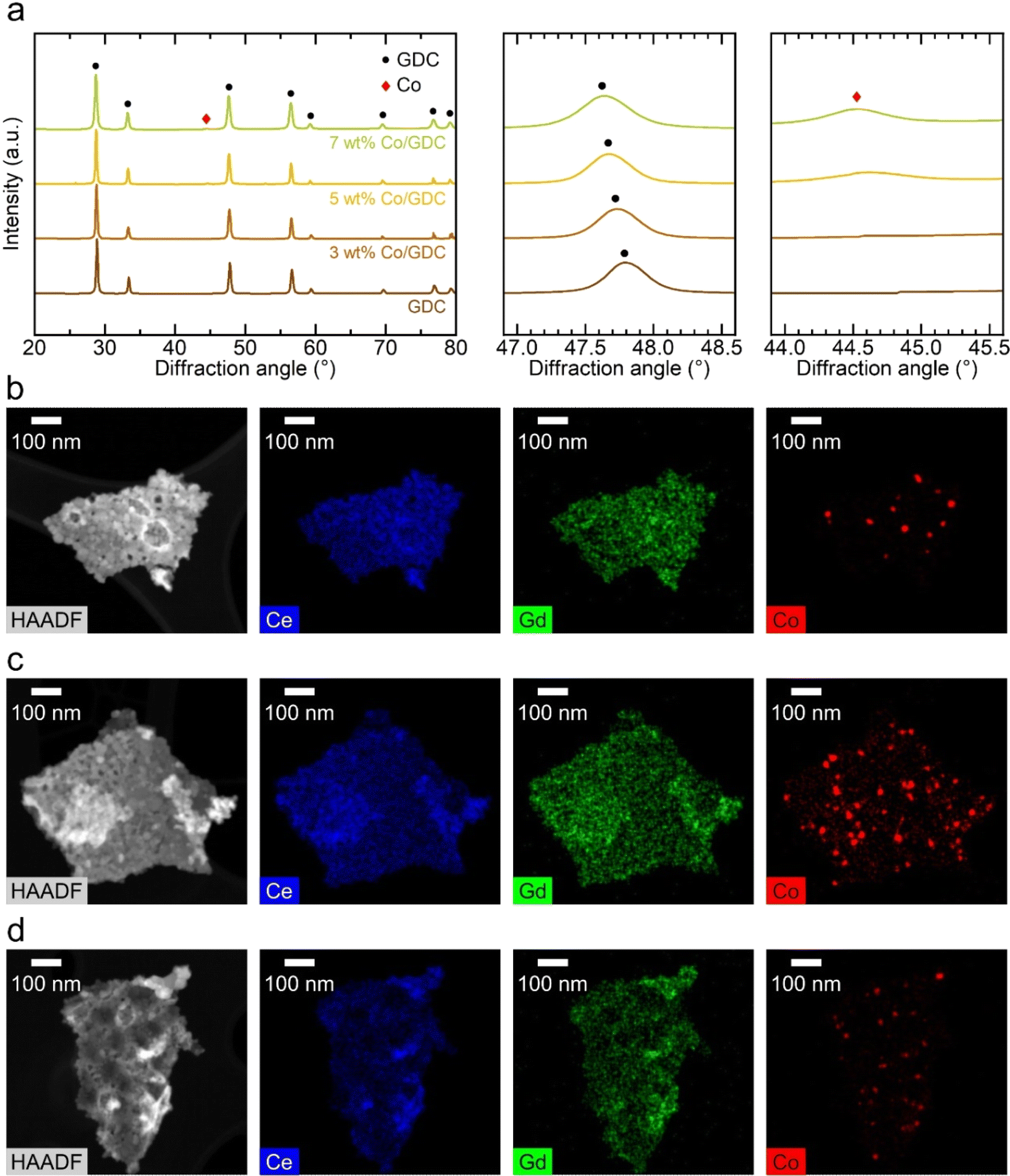 | ||
| Fig. 1 Structural analysis of cobalt-embedded GDC. (a) XRD patterns and (b–d) HAADF-STEM and TEM-EDS mapping images of GDC containing (b) 3 wt%, (c) 5 wt%, and (d) 7 wt% Co showing the chemical distributions of the constituent elements. | ||
To evaluate the electrocatalytic performance of nanocatalysts, we fabricated symmetric cells and characterized them electrochemically using impedance spectroscopy. In these symmetric cells, the electrolyte substrate was ∼3 mm thick, with a ∼20 μm-thick Ni–YSZ electrode and a ∼5 μm-thick Ni current collecting layer sequentially deposited on both sides of the YSZ substrate. In the microstructure of the symmetric cell shown on the left side of Fig. 2(a), the electrode thickness is uniform, and all interfaces are intact, showing no signs of processing defects. The right side of Fig. 2(a) displays the inner surface of the porous Ni–YSZ electrode, composed of approximately 500 nm particles, with the surface bare before infiltration. After infiltration, nanocatalysts uniformly covered the entire surface, and the size and morphology of the infiltrated particles were similar for the GDC nanocatalysts with various cobalt contents (0, 3, 5, and 7 wt%, as shown in Fig. 2(b)–(e), respectively). The particle size was approximately 30 nm, which matches the TEM observations in Fig. 1(b)–(d), and the majority of the inner surface area was covered with infiltrated particles. The infiltration was carried out prior to the reduction of NiO, and no significant changes were observed following the conversion of NiO to metallic Ni, as illustrated in Fig. S4.† Furthermore, SEM-EDS analysis in Fig. S5† confirmed that the infiltrated nanoparticles retained consistent sizes and distributions, whether formed on Ni or YSZ.
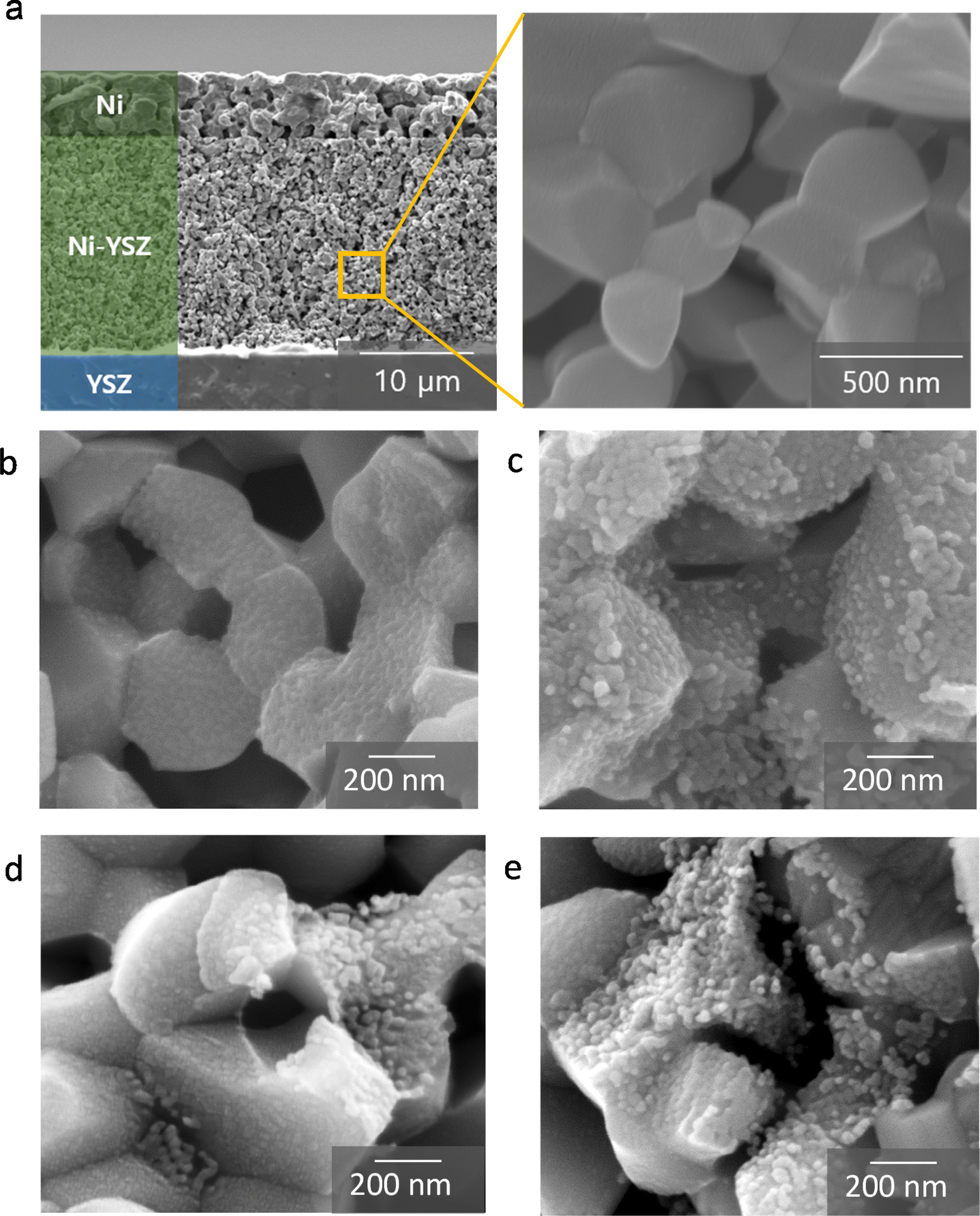 | ||
| Fig. 2 Fabrication of symmetric cells with cobalt-embedded GDC. (a) SEM images of the entire fuel electrode and bare inner surface before infiltration. (b–e) SEM images of the inner surface infiltrated with GDC containing (b) 0 wt%, (c) 3 wt%, (d) 5 wt%, and (e) 7 wt% Co. | ||
The Nyquist plots of the impedance spectra for the symmetric cells measured at 700 °C are shown in Fig. 3(a). In a Nyquist plot, the size of the arc represents the polarization resistance. For the bare Ni–YSZ electrode, the polarization resistance was 0.23 Ω cm2, and it decreased to 0.14 Ω cm2 after the infiltration of GDC nanocatalysts. The polarization resistance further decreased with the various additions of cobalt. The impedance spectra for cells infiltrated with cobalt-embedded GDC nanocatalysts can be more clearly seen in Fig. 3(b). The polarization resistance of the GDC nanocatalysts with 3 wt% cobalt was 0.13 Ω cm2, which decreased to 0.10 Ω cm2 as the cobalt content increased to 5 wt%. However, further increasing the cobalt content to 7 wt% increased the polarization resistance back to 0.13 Ω cm2. These results indicate that the addition of cobalt nanoparticles to GDC enhances its catalytic activity, but excessive cobalt is detrimental to the electrochemical reaction and increases the polarization resistance, likely because of particle aggregation.
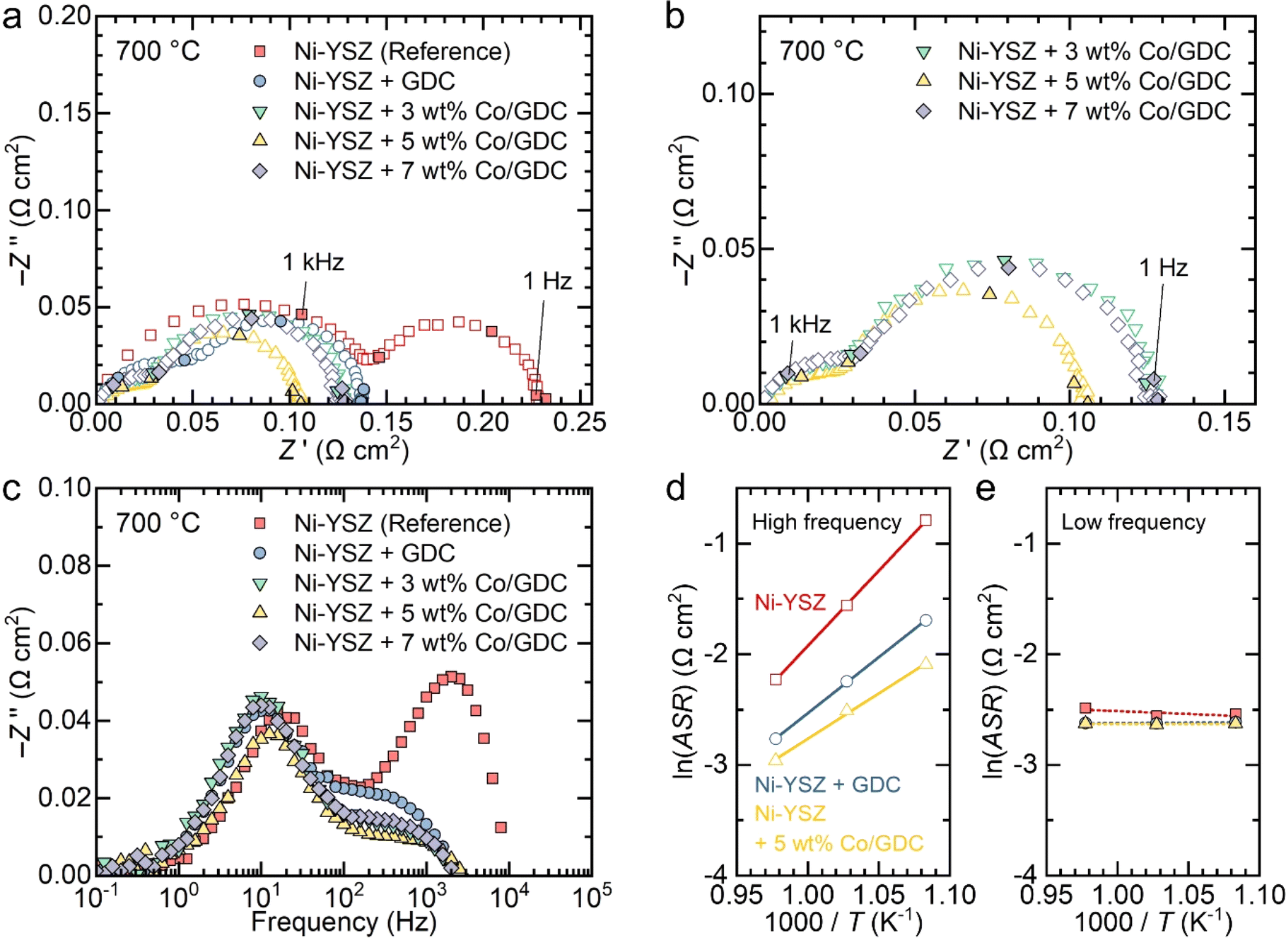 | ||
| Fig. 3 Electrochemical performance of symmetric cells. (a–b) Nyquist and (c) Bode plots of impedance spectra of the symmetric cells with and without 0, 3, 5, and 7 wt% cobalt-embedded GDC at 700 °C with 3% H2O. (d–e) Arrhenius plots of (d) high- and (e) low-frequency impedance arcs of bare Ni–YSZ, GDC-infiltrated Ni–YSZ, and 5 wt% cobalt-embedded GDC-infiltrated Ni–YSZ electrodes. | ||
The Bode plots of the imaginary part of the impedance spectra in Fig. 3(c) indicate that high-frequency impedance is predominantly affected by the infiltration of nanocatalysts, whereas the low-frequency impedance is insensitive to it. The impedance spectra of the fuel electrode consist of multiple arcs with different characteristic frequencies, each representing individual rate-limiting processes. Typically, the high-frequency arc corresponds to the charge transfer reaction, and the low-frequency arc corresponds to gas diffusion.17,39–44 The Bode plots in Fig. 3(c) clearly show that the charge transfer reaction is significantly enhanced by the infiltration of nanocatalysts and is sensitive to the cobalt content, while gas diffusion remains unaffected by infiltration. GDC is a reducible 4f oxide with mixed ionic and electronic conductivity in reducing environments, which enables the access of both types of carriers to solid–gas interface. It also possesses excellent redox properties with high oxygen storage capacity, which provides high electrocatalytic activity.23 Incorporating cobalt over ceria further promote electrocatalytic reaction by providing adsorption sites for reactants, facilitating hydrogen spillover and promoting strong metal–support interactions.45 The dispersion of cobalt on ceria significantly influences the catalytic properties,46,47 and we achieved an excellent uniform distribution of cobalt nanoparticles on ceria, resulting in superior electrocatalytic properties and substantial performance improvements. We also measured the impedance of symmetric cells with different numbers of infiltration cycles. As shown in Fig. S6,† high-frequency impedance was more sensitive to the number of infiltration cycles compared to low-frequency impedance. This suggests that the charge transfer reaction, which dominates high-frequency impedance, is significantly enhanced by the infiltrated nanoparticles and is sensitive to the amount of nanocatalyst loading. In contrast, the low-frequency impedance arc was less sensitive to the nanocatalyst loading content, possibly because the infiltrated nanoparticles occupy only a small volume fraction and have minimal impact on gas diffusion. The impedance spectra of the symmetric cells measured at 750 and 650 °C are shown in Fig. S7.† The spectra were deconvoluted into two arcs using an equivalent circuit fitting with a circuit composed of two resistance (R)–constant phase element (CPE) units, as shown in Fig. S8.† The obtained polarization resistance values for the high- and low-frequency arcs are listed in Table S1.† Using these values, an Arrhenius plot was constructed to determine the activation energies for the two arcs in each electrode, as shown in Fig. 3(d) and (e). The activation energy for the high-frequency impedance in the bare Ni–YSZ electrode was found to be 113 kJ mol−1, which agrees well with the reported values for the charge transfer reaction in the H2 oxidation reaction.48–51 Introducing GDC nanocatalysts decreased the activation energy to 84.1 kJ mol−1, and further addition of 5 wt% cobalt nanoparticles to GDC decreased it to 68.2 kJ mol−1 (Fig. 3(d)). In contrast, the low-frequency impedance depended negligibly on temperature, which is characteristic of gas diffusion (Fig. 3(e)).
Next, we examined the nanocatalyst performance in full cells supported by the fuel electrode in both fuel cell and electrolysis modes. Specifically, we infiltrated the electrode with the GDC nanocatalyst containing 5 wt% cobalt, which demonstrated the highest performance in symmetric cell measurements. The cell was composed of ∼100 μm-thick Ni–YSZ substrate, a ∼12 μm-thick Ni–YSZ fuel electrode functional layer, a ∼5 μm-thick YSZ electrolyte, a ∼1 μm-thick GDC diffusion barrier layer, and a ∼15 μm-thick LSC air electrode. The microstructure of the fabricated cell is shown in Fig. 4(a) and (b) provides a high-magnification image of the functional layer after infiltration. In fuel-electrode-supported cells, infiltrating nanocatalysts into the fuel electrode poses two main challenges. First, the presence of the thick fuel electrode substrate makes it difficult for the precursor solution to penetrate the entire fuel electrode support. Second, although nanocatalysts are needed in the functional layer where electrochemical reactions occur, the functional layer is dense before the reduction of NiO to metallic Ni, allowing only limited penetration of the chemical solution into the few pores present. In this study, we addressed the first challenge by making a thin fuel electrode. As shown in Fig. 4(a), we used a thin substrate with a thickness of ∼100 μm to ensure thorough infiltration of the chemical solution throughout the entire structure. To maintain the mechanical strength, we used 3 mol% YSZ for the Ni–YSZ substrate, while 8 mol% YSZ was used for the functional layer and electrolyte to ensure high oxygen ion conductivity. To mitigate the second challenge related to the functional layer density, we increased the porosity of this layer before reduction by sintering the substrate at a relatively low temperature of 1350 °C and introducing additional porosity using carbon black nanopowder as a pore former.32 The porous structure of our functional layer is compared with a conventional dense functional layer in Fig. S9.† Then, we applied our urea-based infiltration process, which produces uniformly distributed nanoparticles throughout the porous electrode, with urea acting as a precipitation agent.52 In particular, in our urea-based infiltration solution, urea thermally decomposes at around 80 °C, releasing ammonia and carbon dioxide into the solution. This decomposition leads to homogeneous precipitation with minimal liquid migration, ensuring a uniform distribution of infiltrated nanoparticles with little aggregation or spatial segregation. As a result, the chemical solution successfully infiltrated the functional layer where electrocatalysts are needed, and the nanocatalysts formed uniformly over the inner surface of the pores in the functional layer, as illustrated in Fig. 4(b). The size of the infiltrated particles in the full cell is estimated to be ∼50 nm, which is slightly larger than those in symmetric cells. This difference is attributed to the different thermal history because the full cells were subjected to a higher temperature of 850 °C during the sealing process.
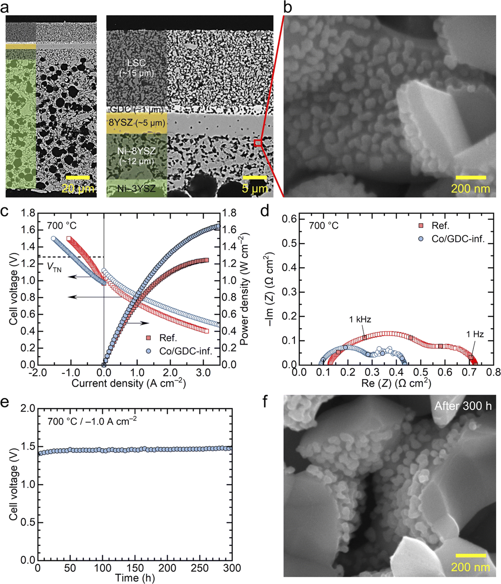 | ||
| Fig. 4 Practical application of 5 wt% cobalt-embedded GDC nanocatalysts in a fuel-electrode-supported full cell. (a and b) Cross-sectional SEM images of the tested full cell infiltrated with cobalt-embedded GDC. (c) i–V curves in fuel cell and electrolysis modes and (d) Nyquist plots of the impedance spectra of full cells operating in fuel cell mode at 700 °C with and without Co/GDC infiltration. (e) Long-term stability test at 700 °C at −1.0 A cm−2 in a 50% H2O environment. (f) Postmortem analysis of cobalt-embedded GDC nanocatalysts in the Ni–YSZ fuel electrode functional layer. | ||
The cell infiltrated with 5 wt% cobalt-embedded GDC nanocatalysts was electrochemically tested in both fuel cell and electrolysis modes, and its performance was compared with a reference cell without nanocatalysts. Fig. 4(c) presents the i–V curves and corresponding power densities of the two cells measured at 700 °C. In fuel cell mode, the cells were tested using 3% humidified hydrogen as fuel and dry air as the oxidant. Both cells exhibited near-theoretical open circuit voltages (OCVs), confirming that the cells and seals were leak-tight in all experiments. The reference cell achieved a maximum power density of ∼1.2 W cm−2, which is slightly higher than the typical performance of regular fuel-electrode-supported cells with LSC air electrodes.32,53 This higher performance was likely due to the thinner substrate used in our study compared with that of typical cells reported in the literature. With the infiltration of nanocatalysts, the performance of the cell significantly improved, with the maximum power density increasing to ∼1.7 W cm−2 under the same conditions. Performance in electrolysis mode also improved substantially with nanocatalyst infiltration. The electrolysis performance was measured with a supply of 50% H2O–50% H2 to the fuel electrode and dry air to the air electrode. The electrolysis current density, which corresponds to the hydrogen production rate, increased from 0.54 to 0.94 A cm−2 at the thermoneutral voltage of 1.28 V, indicating that nanocatalyst infiltration increased the hydrogen production rate by approximately 74% at fixed cell voltage. Alternatively, if we compare the cell voltage at a fixed current density, nanocatalyst infiltration results in a lower voltage and, consequently, higher efficiency. The results in Fig. 4(c) suggest that cobalt-embedded GDC nanocatalysts are highly active for both hydrogen oxidation and steam decomposition reactions. Additional i–V curves for the two cells measured at 750 and 650 °C are shown in Fig. S10.†
The impedance spectra of the two cells measured at 700 °C in fuel cell mode (97% H2–3% H2O) are compared in Fig. 4(d). Consistent with the symmetric cell measurements, the cell infiltrated with nanocatalysts exhibits significantly lower polarization resistance, and its Bode plot shows a lower high-frequency impedance (Fig. S11†), also agreeing with the symmetric cell results. In addition, the ohmic resistance, indicated by the high-frequency intercept in the Nyquist plots, slightly decreased with nanocatalyst infiltration. The ohmic resistance also decreased in previous studies, which could be attributed to the formation of additional local conduction paths, particularly at interfaces with poor connectivity.10,31 The impedance spectra of the two cells measured at 750 and 650 °C are shown in Fig. S12.†
The long-term stability of the cell infiltrated with nanocatalysts is presented in Fig. 4(e). The thermal stability of nanoparticles is a major concern during high-temperature operation because they are highly active and tend to aggregate when exposed to high temperatures for extended periods. The cell infiltrated with nanocatalysts was tested at a constant current density of −1.0 A cm−2 in electrolysis mode, with 50% H2O–50% H2 supplied to the fuel electrode at 700 °C for 300 h. During the first 50 hours, the cell voltage increased by 14 mV from 1.431 to 1.445 V, and then remained very stable over the next 250 hours, with a minimal increase in cell voltage from 1.445 to 1.453 V. This corresponds to a degradation rate of 2.2% kh−1. Given that the cell was operated under harsh conditions, including high current density and voltage, and that we used realistic metallic interconnects without protective coatings, this degradation rate is very low, demonstrating the stability of our infiltrated nanoparticles. While the initial increase in cell voltage during the first 50 hours is not significant, this early-stage degradation is believed to be primarily caused by Cr poisoning of the air electrode, as observed in previous studies.32 We used a metallic interconnect made of Inconel, which causes substantial Cr evaporation during the initial stages of operation. Over time, Cr evaporation decreases as an oxide scale forms on the surface of the Inconel. The impedance spectra of the cell before and after long-term operation, shown in Fig. S13(a),† indicate a slight increase in ohmic resistance, while changes in polarization resistance were relatively minimal. Post-mortem SEM analysis in Fig. S13(b)† revealed the localized formation of a dense layer on the air electrode surface, with significant amounts of Sr and Cr detected by EDS analysis. This suggests the formation of Sr–Cr oxide resulting from the reaction between Cr vapor and Sr segregated from the LSC air electrode. The insulating Sr–Cr oxide layer formed at the electrical contact between the air electrode and the current collector increased the ohmic resistance, causing the slight rise in cell voltage during the initial operation. The long-term test results in Fig. 4(e) indicates that the nanocatalysts in the fuel electrode were thermally stable, even under the extremely harsh conditions of electrolysis mode, which exposed the nanocatalysts to large amounts of steam. Furthermore, the structural characteristics of these nanocatalysts did not significantly change after long-term operation, with the estimated particle size of ∼50 nm (Fig. 4(f)), further proving their excellent thermal stability.
Conclusions
With the remarkable advancement of air electrode materials, the importance of the fuel electrode is now widely recognized. However, replacing Ni-based materials with other high-performance alternatives is challenging because of the constraints imposed by the high-temperature co-firing process. In this study, we enhanced the performance of conventional Ni-based fuel electrodes by decorating their surface with nanocatalysts using an infiltration technique. Cobalt-embedded GDC nanocatalysts effectively improved cell performance and demonstrated thermal stability under harsh operating conditions. This infiltration process is simple, cost-effective, and scalable, making it a promising approach for enhancing the performance and stability of SOCs in practical applications.Data availability
The data supporting this article have been included as part of the ESI.†Author contributions
H. Cho: investigation, data curation, formal analysis, methodology, validation, writing – original draft; H. Seo: investigation, formal analysis, methodology, resources, visualization, writing – original draft, writing – review & editing; J. Min: investigation, resources; J. Hong: funding acquisition, supervision; K. J. Yoon: conceptualization, funding acquisition, supervision, writing – original draft, writing – review & editing.Conflicts of interest
There are no conflicts to declare.Acknowledgements
This work was supported by the National Research Foundation (NRF) of the Korean Ministry of Science & ICT through the Technology Development Program to Solve Climate Changes (No. 2020M1A2A2080862) and the institutional research program of the Korea Institute of Science and Technology (KIST). We thank Lauren Plavisch for English Editing.References
- S. Y. Gómez and D. Hotza, Renew. Sustain. Energy Rev., 2016, 61, 155–174 CrossRef
.
- A. Hauch, R. Küngas, P. Blennow, A. B. Hansen, J. B. Hansen, B. V. Mathiesen and M. B. Mogensen, Science, 2020, 370, eaba6118 CrossRef CAS
- H. Nirasawa, ECS Trans., 2017, 78, 33–40 CrossRef CAS
- H. Sumi, S. Nakabayashi, T. Kawada, Y. Uchiyama, N. Uchiyama and K. Ichihara, ECS Trans., 2019, 91, 149–157 CrossRef CAS
- S. B. Adler, Chem. Rev., 2004, 104, 4791–4844 CrossRef CAS
- K. J. Yoon, M. Biswas, H. J. Kim, M. Park, J. Hong, H. Kim, J. W. Son, J. H. Lee, B. K. Kim and H. W. Lee, Nano Energy, 2017, 36, 9–20 CrossRef CAS
- D. W. Joh, A. Cha, J. H. Park, K. J. Kim, K. T. Bae, D. Kim, Y. K. Choi, H. An, J. S. Shin, K. J. Yoon and K. T. Lee, ACS Appl. Nano Mater., 2018, 1, 2934–2942 CrossRef CAS
- S. P. Jiang, Int. J. Hydrogen Energy, 2019, 44, 7448–7493 CrossRef CAS
- H. Shimada, T. Yamaguchi, H. Kishimoto, H. Sumi, Y. Yamaguchi, K. Nomura and Y. Fujishiro, Nat. Commun., 2019, 10, 5432 CrossRef
- H. Seo, M. Kishimoto, C. Ding, H. Iwai, M. Saito and H. Yoshida, Fuel Cells, 2020, 20, 570–579 CrossRef CAS
- X. F. Tong, S. Ovtar, K. Brodersen, P. V. Hendriksen and M. Chen, J. Power Sources, 2020, 451, 227742 CrossRef CAS
- K. Develos-Bagarinao, T. Ishiyama, H. Kishimoto, H. Shimada and K. Yamaji, Nat. Commun., 2021, 12, 3979 CrossRef CAS PubMed
- J. Shin, S. Yang, H. I. Ji, S. Park, H. Kim, J. W. Son, J. H. Lee, B. K. Kim, J. Hong and K. J. Yoon, J. Alloys Compd., 2021, 868, 159092 CrossRef CAS
- M. Y. Park, J. Shin, S. Y. Park, J. E. Won, J. Y. Hwang, S. K. Hong, S. W. Kim, J. H. Jang and K. J. Yoon, Chem. Eng. J., 2023, 476, 146924 CrossRef
- H. Shimada, H. Sumi, Y. Yamaguchi, K. Nomura, Y. Mizutani, Y. Fujishiro and W. Shin, J. Power Sources, 2023, 563, 232781 CrossRef CAS
- Y. Zhang and J. D. Nicholas, J. Electrochem. Soc., 2021, 168, 034513 CrossRef CAS
- H. Sumi, T. Yamaguchi, K. Hamamoto, T. Suzuki, Y. Fujishiro, T. Matsui and K. Eguchi, Electrochim. Acta, 2012, 67, 159–165 CrossRef CAS
- H. Shimada, T. Suzuki, T. Yamaguchi, H. Sumi, K. Hamamoto and Y. Fujishiro, J. Power Sources, 2016, 302, 53–60 CrossRef CAS
- H. Seo, H. Iwai, M. Kishimoto, C. S. Ding, M. Saito and H. Yoshida, J. Power Sources, 2020, 450, 227682 CrossRef CAS
- A. Hussain, R. H. Song, M. Z. Khan, T. H. Kim, J. E. Hong, D. W. Joh, H. A. Ishfaq, S. B. Lee and T. H. Lim, J. Power Sources, 2023, 573, 233160 CrossRef CAS
- H. Sumi, H. Shimada, Y. Yamaguchi, K. Nomura and K. Sato, Electrochim. Acta, 2023, 443, 141965 CrossRef
- C. Ding, H. Seo, M. Kishimoto and H. Iwai, Fuel Cells, 2023, 23, 264–272 CrossRef
- W. C. Chueh, Y. Hao, W. Jung and S. M. Haile, Nat. Mater., 2012, 11, 155–161 CrossRef PubMed
- J. A. Lane and J. A. Kilner, Solid State Ionics, 2000, 136–137, 927–932 CrossRef
- J. Grimes, J. Hong and S. A. Barnett, J. Power Sources, 2022, 551, 232189 CrossRef
- S. Ovtar, X. Tong, J. J. Bentzen, K. T. S. Thydén, S. B. Simonsen and M. Chen, Nanoscale, 2019, 11, 4394–4406 RSC
- B.-K. Park, R. Scipioni, D. Cox and S. A. Barnett, J. Mater. Chem. A, 2020, 8, 4099–4106 RSC
- X. Tong, P. V. Hendriksen, A. Hauch, X. Sun and M. Chen, J. Electrochem. Soc., 2020, 167, 024519 CrossRef
- C. Xu, W. Sun, R. Ren, X. Yang, M. Ma, J. Qiao, Z. Wang, S. Zhen and K. Sun, Appl. Catal., B, 2021, 282, 119553 CrossRef
- J. Shin, Y. J. Lee, A. Jan, S. M. Choi, M. Y. Park, S. Choi, J. Y. Hwang, S. Hong, S. G. Park, H. J. Chang, M. K. Cho, J. P. Singh, K. H. Chae, S. Yang, H. I. Ji, H. Kim, J. W. Son, J. H. Lee, B. K. Kim, H. W. Lee, J. Hong, Y. J. Lee and K. J. Yoon, Energy Environ. Sci., 2020, 13, 4903–4920 RSC
- J. Min, H. Seo, J. Shin, M. Y. Park, S. Y. Park, H. Choi, S. Park, S. Yang, H. J. Chang, J. Hong and K. J. Yoon, J. Mater. Chem. A, 2023, 11, 25298–25307 RSC
- H. Seo, S. Jang, W. Lee, K. T. Bae, K. T. Lee, J. Hong and K. J. Yoon, Chem. Eng. J., 2024, 481, 148532 CrossRef
- R. D. Shannon, Acta Crystallogr. A, 1976, 32, 751–767 CrossRef
- M. Chen, B. Hallstedt, A. N. Grundy and L. J. Gauckler, J. Am. Ceram. Soc., 2003, 86, 1567–1570 CrossRef
- J. Q. Wang, M. Q. Shen, J. Wang, J. D. Gao, J. Ma and S. X. Liu, Catal. Today, 2011, 175, 65–71 CrossRef
- S. H. Song, J. Moon, J. H. Kim, J. Hong, J. H. Lee, H. W. Lee, B. K. Kim and H. Kim, Acta Mater., 2016, 113, 206–212 CrossRef
- G. S. Lewis, A. Atkinson, B. C. H. Steele and J. Drennan, Solid State Ionics, 2002, 152–153, 567–573 CrossRef
- E. Jud, Z. Zhang, W. Sigle and L. J. Gauckler, J. Electroceram., 2006, 16, 191–197 CrossRef
- P. Holtappels, L. G. J. de Haart and U. Stimming, J. Electrochem. Soc., 1999, 146, 1620–1625 CrossRef
- R. Barfod, M. Mogensen, T. Klemenso, A. Hagen, Y. L. Liu and P. V. Hendriksen, J. Electrochem. Soc., 2007, 154, B371–B378 CrossRef
- S. Gewies, W. G. Bessler, V. Sonn and E. Ivers-Tiffiée, Solid Oxide Fuel Cells, 2007, 7, 1573–1582 Search PubMed
- A. Leonide, V. Sonn, A. Weber and E. Ivers-Tiffee, J. Electrochem. Soc., 2008, 155, B36–B41 CrossRef
- M. Vogler, A. Bieberle-Hütter, L. Gauckler, J. Warnatz and W. G. Bessler, J. Electrochem. Soc., 2009, 156, B663–B672 CrossRef
- C. Endler, A. Leonide, A. Weber, F. Tietz and E. Ivers-Tiffee, J. Electrochem. Soc., 2010, 157, B292–B298 CrossRef
- A. Parastaev, V. Muravev, E. Huertas Osta, A. J. F. van Hoof, T. F. Kimpel, N. Kosinov and E. J. M. Hensen, Nat. Catal., 2020, 3, 526–533 CrossRef
- H. Song, B. Mirkelamoglu and U. S. Ozkan, Appl. Catal., A, 2010, 382, 58–64 CrossRef
- G. Grzybek, P. Stelmachowski, S. Gudyka, P. Indyka, Z. Sojka, N. Guillén-Hurtado, V. Rico-Pérez, A. Bueno-López and A. Kotarba, Appl. Catal., B, 2016, 180, 622–629 CrossRef
-
B. de Boer, PhD thesis, University of Twente, The Netherland, 1998
- A. Bieberle, L. P. Meier and L. J. Gauckler, J. Electrochem. Soc., 2001, 148, A646–A656 CrossRef
- B. Hua, M. Li, B. Chi and L. Jian, J. Mater. Chem. A, 2014, 2, 1150–1158 RSC
- M. Kishimoto, H. Onaka, H. Iwai, M. Saito and H. Yoshida, J. Power Sources, 2019, 431, 153–161 CrossRef
- K. J. Yoon, M. Biswas, H.-J. Kim, M. Park, J. Hong, H. Kim, J.-W. Son, J.-H. Lee, B.-K. Kim and H.-W. Lee, Nano Energy, 2017, 36, 9–20 CrossRef
- M. Young Park, J. Shin, S.-Y. Park, J.-e. Won, J. Yeon Hwang, S. Hong, S.-W. Kim, J.-H. Jang and K. Joong Yoon, Chem. Eng. J., 2023, 476, 146924 CrossRef
Footnotes |
| † Electronic supplementary information (ESI) available: TEM and SEM images, impedance spectra, equivalent circuit model, polarization resistance analysis. See DOI: https://doi.org/10.1039/d4ta03979c |
| ‡ These authors equally contributed to this work. |
| This journal is © The Royal Society of Chemistry 2024 |