 Open Access Article
Sn–carbon nanocomposite anode for all-solid-state chloride-ion batteries operating at room temperature†
Hyeonsu
Yang
 ab,
Seonghee
Kim
a,
Sungho
Lee
a,
Liwei
Zhao
c,
Atsushi
Inoishi
 *c,
Hikari
Sakaebe
 *c,
Ken
Albrecht
 *c and
Oi Lun
Li
 *a
*a
aDepartment of Materials Science and Engineering, Pusan National University, 2 Busandaehak-ro 63beon-gil, Geumjeong-gu, Busan 46241, Republic of Korea. E-mail: helenali@pusan.ac.kr
bInterdisciplinary Graduate School of Engineering Sciences, Kyushu University, 6-1 Kasuga-Koen, Kasuga-shi, Fukuoka 816-8580, Japan
cInstitute for Materials Chemistry and Engineering, Kyushu University, Kasuga-koen 6-1, Kasuga, Fukuoka 816-8580, Japan. E-mail: inoishi@cm.kyushu-u.ac.jp; sakaebe@cm.kyushu-u.ac.jp; albrecht@cm.kyushu-u.ac.jp
First published on 31st December 2024
Abstract
All-solid-state chloride-ion batteries promise high theoretical energy density and room-temperature operation. However, conventional Sn anodes suffer from low material utilization attributed to large particle size and volume expansion. Here, nano-sized Sn particles in an N-doped carbon framework are used as an anode, resulting in ∼12% higher capacity compared to conventional Sn, due to improved Sn utilization and suppression of volume expansion.
Lithium-ion batteries (LIBs) have been the dominant energy storage technology for several decades, known for their high energy density and reliability.1,2 However, with advances in energy storage technology and increasing demand for higher performance, LIBs are nearing their theoretical energy density limits.3,4 This limitation is becoming a significant challenge in applications that require greater energy storage capacity, such as electric vehicles and large-scale grid energy storage. Additionally, the use of liquid electrolytes in LIBs poses a significant fire risk due to their low thermal stability.5 To address these challenges, efforts are ongoing to develop alternative battery systems.6–8 Among these, all-solid-state batteries, with solid electrolytes and components, offer notable advantages in safety and energy density.9
Halogen-ion-based batteries have attracted attention due to their high energy density.10 Anion-based systems, including those utilizing Cl−, F−, and PF6−, differ from metal cation-based systems in that anions can form hybrid covalent-ionic bonds with the electrode materials.11–13 This interaction introduces additional redox sites, enhancing electrochemical performance.14 Chloride ions, in particular, stand out due to their high theoretical volumetric and gravimetric energy densities.15 Moreover, chloride ions are abundant and inexpensive, contributing to the potential for large-scale, cost-effective energy storage solutions.
Recently, a solid electrolyte based on the perovskite-type CsSnCl3, which exhibits high chloride ionic conductivity, has been developed.16 This solid electrolyte, when paired with a BiCl3 cathode and a Sn anode, provides promising cycling performance in ASS chloride-ion batteries. However, CsSnCl3 is metastable and undergoes phase transitions at room temperature, transforming into a stable phase with lower conductivity.17,18 To improve its phase stability at room temperature, elements with smaller ionic radii, such as Mn, In, or Y can be introduced.18,19 These elements stabilize the structure and prevent phase transitions, allowing for better performance in all-solid-state batteries under ambient conditions. We have recently discovered that CsSn0.95Y0.05Cl3.05 (CSYC) exhibits a high chloride ionic conductivity of 4.9 mS cm−1 at room temperature, and we have demonstrated excellent charge–discharge performance by combining a Sn anode with a BiCl3 cathode.19 Despite these benefits, a significant challenge remains: the volume expansion of metal electrodes during charge and discharge.20 This volume change leads to increased interfacial resistance, reducing the battery's efficiency and long-term stability. The performance of solid-state batteries is especially susceptible to these issues, as the solid–solid interface between the electrode and electrolyte can degrade over time.21
Many studies have focused on engineering electrode materials at the nanoscale to address this issue.22,23 By reducing the size of metal particles used in the anode and embedding them into a conductive matrix, such as nitrogen-doped (N-doped) carbon, the effects of volume expansion can be mitigated.24 The N-doped carbon not only provides structural support to reduce mechanical stress but also enhances electron transport, leading to improved overall performance.25 These composite materials are expected to offer superior cycling stability and higher capacity retention compared to conventional metal anodes.
In this study, a composite of Sn nanoparticles dispersed in N-doped carbon (Sn@NC) is synthesized using a one-step plasma engineering. By combining nano-sized Sn with N-doped carbon, this work aims to suppress the volume expansion that occurs during SnCl2 formation. The electrochemical performance of the synthesized material is evaluated as an anode for all-solid-state chloride-ion batteries at room temperature, and its performance is compared to that of a conventional Sn anode.
As shown in Fig. 1(a), Sn@NC was synthesized via plasma engineering. The synthesis route was composed of a N,N-dimethylformamide (DMF) solution and two Sn electrodes facing each other in a plasma reactor. When a pulse power was applied between the electrodes, plasma was generated and the precursor vaporized due to Joule heating. Radicals are formed depending on the type of precursors and electrodes, and these can be observed using optical emission spectroscopy (OES).26Fig. 1(b) shows the spectra from the plasma region during synthesis. The main radical species, such as CN, CH, C2, and Hα, show strong intensity peaks. These radicals are important intermediates in the polymerization and carbonization of the organic solution. In addition, clear Sn related peaks appeared at around 580, 645, and 690 nm, indicating that Sn is involved in the carbon polymerization caused by the CN, CH, and C2 radicals. Therefore, DMF serves as both a carbon source and nitrogen dopant through its decomposition into reactive intermediates, while the Sn electrode provides Sn nanoparticles that integrate into the carbon matrix to form Sn@NC.
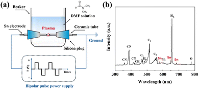 | ||
| Fig. 1 (a) Schematic of the experimental setup for plasma engineering; (b) OES spectrum during the plasma engineering. | ||
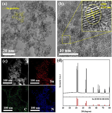
The morphology and microstructure of the synthesized Sn@NC material were observed using scanning electron microscope (Fig. S1, ESI†) and transmission electron microscope (TEM) images. Through the TEM image (Fig. 2(a) and Fig. S2, ESI†), it is shown that spherical Sn@NC particles are uniformly distributed, with an overall size of 3–5 nm. The high-resolution TEM image (Fig. 2(b)) shows that the particles have lattice spacing corresponding to the (200) planes of metallic Sn. Additionally, the energy dispersive X-spectrometry (EDS) mapping result (Fig. 2(c)) confirms that Sn particles are distributed within the carbon matrix. The elemental composition from TEM-EDS analysis reveals Sn, C, N, and O at 43.5, 37.0, 5.3, and 14.2 wt%, respectively. While TEM images indicate that Sn nanoparticles are generally well-distributed within the N-doped carbon framework, partial agglomeration is observed, likely due to the high-temperature and electric field conditions of the plasma synthesis process, which can cause localized clustering during rapid vaporization and condensation. To further confirm the Sn content in Sn@NC, inductively coupled plasma optical emission spectrometry (ICP-OES) was conducted, showing a Sn weight percentage of 46.4 wt%. Additionally, thermogravimetric analysis was used to calculate the Sn content, which was found to be approximately 46.2 wt% (Fig. S3, ESI†). These values are all in close agreement, indicating that nano-sized Sn particles are successfully integrated with the N-doped carbon matrix through plasma engineering. Fig. 2(d) shows the X-ray diffraction (XRD) pattern of Sn@NC. A distinct Sn peak is observed, indicating the successful incorporation of Sn into the synthesized material. However, due to the strong Sn metal peak, observing the peak of carbon was challenging. Raman spectra of Sn@NC, given in Fig. S4 (ESI†), exhibit the characteristic peaks for disordered (D band) and graphitic carbon (G band). The ID/IG ratio for Sn@NC is 1.04, suggesting the presence of a significant fraction of the amorphous structure in the carbon framework.
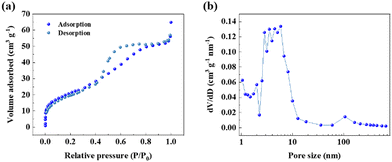
The pore structure and surface area of the Sn@NC were examined using N2 adsorption–desorption isotherms, as shown in Fig. 3(a). The isotherm exhibited a type-IV hysteresis, suggesting the presence of abundant mesopores within the material.27 According to the pore size distribution confirmed by the Barrett–Joyner–Halenda method (Fig. 3(b)), most of the pores are distributed in the range of 2 to 10 nm. The surface area of Sn@NC was measured to be 76.35 m2 g−1, the total pore volume was 0.0856 cm3 g−1, and the average pore size was 4.485 nm. This large surface area and pore structure of the carbon shell act as a buffer, reducing volume expansion when Sn complexes with chloride ions.
To evaluate the electrochemical performance of Sn@NC as an anode for all-solid-state chloride-ion batteries operated at room temperature, a battery cell (Sn@NC/CSYC/BiCl3) was assembled, and the schematic is shown in Fig. 4(a). BiCl3-based material was used as the cathode, while the synthesized Sn@NC material was used as the anode. CSYC was employed as a solid electrolyte. Fig. 4(b) compares the charge/discharge profiles of the first two cycles for cells assembled with the Sn@NC anode and an equivalent amount of the conventional Sn anode. The profiles suggest the following redox reactions at each electrode. At the BiCl3 cathode, Bi3+ is reversibly reduced and oxidized (BiCl3 + 3e− ↔ Bi + 3Cl−), while at the Sn-based anode, Sn undergoes reversible oxidation and reduction (Sn + 2Cl− ↔ SnCl2 + 2e−). These redox reactions, driven by the migration of Cl− ions between the electrodes, maintain charge balance during cycling.16,18 The capacity of the cell was presented based on the cathode. The Sn@NC anode exhibited a discharge capacity of 188.5 mA h g−1 in the first cycle, followed by a charge capacity of 135.8 mA h g−1, resulting in an efficiency of about 72%. In the second cycle, the discharge and charge capacities of Sn@NC were 140.1 mA h g−1 and 128.9 mA h g−1, respectively, with an average voltage of ∼0.3 V. In contrast, the conventional Sn anode showed a discharge capacity of 153 mA h g−1 and a charge capacity of 108 mA h g−1 in the first cycle. In the second cycle, the discharge and charge capacities were 118 mA h g−1 and 107 mA h g−1, respectively. Such capacities are more than 15% lower compared to Sn@NC from the perspective of the anode. These results indicate that the nano-sized Sn particles in Sn@NC contribute to the improved capacity of the anode. However, the slightly lower capacity retention of Sn@NC in the early cycles may be due to larger volume changes associated with its higher utilization rate of BiCl3.
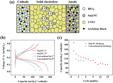 | ||
| Fig. 4 (a) Schematic diagram of the all-solid-state Cl-ion battery; (b) charge–discharge profiles; and (c) cycling performance of the Sn@NC/CSYC/BiCl3 and conventional Sn/CSYC/BiCl3 cells. | ||
Fig. 4(c) shows the cycling performance of Sn@NC and conventional Sn anode. Over 15 cycles, the discharge capacity of the Sn@NC anode decreases to about 95.6 mA h g−1. This capacity reduction is due to the increase in interfacial resistance between the electrolyte and the anode, as well as between the electrolyte and the cathode, caused by the volume expansion of Sn and BiCl3. In contrast, the conventional Sn anode exhibited a discharge capacity of approximately 110 mA h g−1 by the 5th cycle, which is 12% lower than the 5th discharge capacity of Sn@NC (125 mA h g−1). This improvement in the Sn@NC anode can be attributed to the enhanced capacity from the nano-sized Sn particles and the carbon shell, which mitigates the volume expansion during charge and discharge. While the Sn@NC anode achieves a higher initial utilization of the BiCl3 cathode compared to the conventional Sn anode (74.1% vs. 60.4%), this may lead to greater volume changes and interfacial degradation. Future studies should focus on optimizing electrode composition and interface stability. It is also noted that the performance of the battery using the conventional Sn anode this time is lower than in our previous report.19 However, this is because the amount of Sn has been reduced to match the amount of Sn@NC, compared to the previous report.
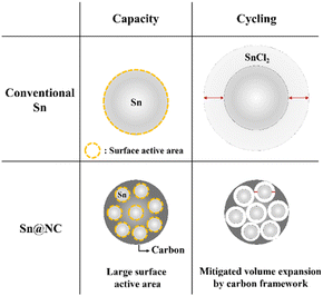
The key point in these results is that, despite the same amount of Sn being used in the anode for both cases, there is a noticeable difference in capacity and cycling performance. The differences in capacity and cycling performance between Sn@NC and conventional Sn are summarized in Scheme 1. Regarding capacity, the conventional Sn powder used in this experiment has a size of ∼75 μm. Therefore, during battery discharge, when Sn is converted to SnCl2, the conventional Sn anode cannot utilize all of its Sn source, and only the exposed surface is actively used. In contrast, Sn@NC, with its nano-sized Sn distribution, allows for a higher proportion of the Sn source to participate in the redox reactions, significantly enhancing capacity. This highlights the nanoscale Sn distribution as the dominant factor contributing to the increased capacity. In terms of cycling performance, metals commonly experience significant volume changes during the formation of metal chlorides through conversion reactions, and this is also the case for Sn.10,28 As this phenomenon repeats, the interfacial resistance between the electrode material and the solid electrolyte increases, resulting in performance degradation. However, in Sn@NC, the carbon framework encapsulates the Sn nanoparticles, reducing the volume expansion of Sn and mitigating the performance loss during cycling.
In summary, a Sn–carbon nanocomposite was successfully synthesized via the plasma engineering. The presence and uniform distribution of nano-sized Sn and C were confirmed through TEM images and XRD analysis. The synthesized material was evaluated as an anode for a chloride-ion all-solid-state battery at room temperature. When Sn@NC was applied as the anode, its full cell performance exhibited a discharge capacity of approximately 90.5 mA h g−1 after 15 cycles, with an average voltage of ∼0.3 V. Meanwhile, the capacity of Sn@NC anode was approximately 12% higher than that of a conventional Sn anode at the 5th cycle, likely due to better Sn utilization from the nano-sized particles and the carbon framework suppressing volume expansion during charge and discharge. These findings highlight the potential of Sn@NC as an anode for all-solid-state chloride-ion batteries. Although the operating voltage of the current system is relatively low, advancements in solid electrolyte technology or the introduction of high-energy electrode materials could greatly improve its energy density and applicability in future systems.
This work was supported by a 2-Year Research Grant from Pusan National University and the “Crossover Alliance to Create the Future with People, Intelligence, and Materials” from MEXT, Japan.
Data availability
The data supporting this article have been included as part of the ESI.†Conflicts of interest
There are no conflicts to declare.Notes and references
- N. Nitta, F. Wu, J. T. Lee and G. Yushin, Mater. Today, 2015, 18, 252–264 CrossRef CAS.
- G. Harper, R. Sommerville, E. Kendrick, L. Driscoll, P. Slater, R. Stolkin, A. Walton, P. Christensen, O. Heidrich, S. Lambert, A. Abbott, K. Ryder, L. Gaines and P. Anderson, Nature, 2019, 575, 75–86 CrossRef CAS PubMed.
- Y. Tian, G. Zeng, A. Rutt, T. Shi, H. Kim, J. Wang, J. Koettgen, Y. Sun, B. Ouyang and T. Chen, Chem. Rev., 2020, 121, 1623–1669 CrossRef PubMed.
- J. W. Choi and D. Aurbach, Nat. Rev. Mater., 2016, 1, 1–16 Search PubMed.
- Y. Xiao, Y. Wang, S.-H. Bo, J. C. Kim, L. J. Miara and G. Ceder, Nat. Rev. Mater., 2020, 5, 105–126 CrossRef CAS.
- H. Ma, M. Jiang, Z. Hou, T. Li, X. Zhang, Y. Gao, J. Peng, Y. Li and J.-G. Wang, Energy Storage Mater., 2024, 70, 103411 CrossRef.
- Z. Luo, L. Ren, Y. Chen, Y. Zhao, Y. Huyan, Z. Hou and J.-G. Wang, Chem. Eng. J., 2024, 481, 148448 CrossRef CAS.
- J. Janek and W. G. Zeier, Nat. Energy, 2023, 8, 230–240 CrossRef.
- L. Fan, S. Wei, S. Li, Q. Li and Y. Lu, Adv. Energy Mater., 2018, 8, 1702657 CrossRef.
- J. Yang, Y. Liu, Y. Zhang, G. Wang, X. Shi, H. Zhang, J. Li, P. Deng and X. Tian, Nano Energy, 2023, 110, 108364 CrossRef CAS.
- X. Zhao, S. Ren, M. Bruns and M. Fichtner, J. Power Sources, 2014, 245, 706–711 CrossRef CAS.
- J. Seel and J. Dahn, J. Electrochem. Soc., 2000, 147, 892 CrossRef CAS.
- H. Jiang, Z. Wei, L. Ma, Y. Yuan, J. J. Hong, X. Wu, D. P. Leonard, J. Holoubek, J. J. Razink and W. F. Stickle, Angew. Chem., 2019, 131, 5340–5345 CrossRef.
- G. Liang, F. Mo, X. Ji and C. Zhi, Nat. Rev. Mater., 2021, 6, 109–123 CrossRef CAS.
- R. Sakamoto, N. Shirai, A. Inoishi and S. Okada, ChemElectroChem, 2021, 8, 4441–4444 CrossRef CAS.
- T. Xia, Y. Li, L. Huang, W. Ji, M. Yang and X. Zhao, ACS Appl. Mater. Interfaces, 2020, 12, 18634–18641 CrossRef CAS.
- Z. Wu, Q. Zhang, B. Li, Z. Shi, K. Xu, Y. Chen, Z. Ning and Q. Mi, Chem. Mater., 2019, 31, 4999–5004 CrossRef CAS.
- R. Sakamoto, N. Shirai, Z. Liwei, A. Inoishi, H. Sakaebe and S. Okada, Electrochemistry, 2023, 91, 077003 CrossRef CAS.
- L. Zhao, A. Inoishi, H. Miki, M. Motoyama, S. Okada, T. Asano, A. Sakuda, A. Hayashi and H. Sakaebe, Adv. Energy Sustainability Res., 2024, 5, 2400198 CrossRef CAS.
- W. Zhang, D. Schröder, T. Arlt, I. Manke, R. Koerver, R. Pinedo, D. A. Weber, J. Sann, W. G. Zeier and J. Janek, J. Mater. Chem. A, 2017, 5, 9929–9936 RSC.
- Y. Pang, J. Pan, J. Yang, S. Zheng and C. Wang, Electrochem. Energy Rev., 2021, 4, 169–193 CrossRef CAS.
- Q. Zhang, G. Peng, J. P. Mwizerwa, H. Wan, L. Cai, X. Xu and X. Yao, J. Mater. Chem. A, 2018, 6, 12098–12105 RSC.
- A. K. Parameswaran, J. Azadmanjiri, N. Palaniyandy, B. Pal, S. Palaniswami, L. Dekanovsky, B. Wu and Z. Sofer, Nano Energy, 2023, 105, 107994 CrossRef.
- J. Wu, Z. Pan, Y. Zhang, B. Wang and H. Peng, J. Mater. Chem. A, 2018, 6, 12932–12944 RSC.
- C. Tang, Q. Zhang, M. Q. Zhao, J. Q. Huang, X. B. Cheng, G. L. Tian, H. J. Peng and F. Wei, Adv. Mater., 2014, 26, 6100–6105 CrossRef CAS.
- T. Morishita, T. Ueno, G. Panomsuwan, J. Hieda, A. Yoshida, M. A. Bratescu and N. Saito, Sci. Rep., 2016, 6, 36880 CrossRef CAS.
- F. Sun, J. Gao, Y. Zhu, X. Pi, L. Wang, X. Liu and Y. Qin, Sci. Rep., 2017, 7, 40990 CrossRef CAS PubMed.
- X. Zhao, Z. Zhao-Karger, D. Wang and M. Fichtner, Angew. Chem., Int. Ed., 2013, 52, 13621–13624 CrossRef CAS.
Footnote |
| † Electronic supplementary information (ESI) available. See DOI: https://doi.org/10.1039/d4cc05595k |
| This journal is © The Royal Society of Chemistry 2025 |

