
 Open Access Article
 This Open Access Article is licensed under a
 Creative Commons Attribution 3.0 Unported Licence
Adsorption hierarchy of surfactants and polymers to a damaged hair model: effect of composition, order and polymer size†
Serena
Cozzolino
 ab,
Philipp
Gutfreund
b,
Alexei
Vorobiev
bc,
Rebecca J. L.
Welbourn
d,
Andrew
Greaves
e,
Francesca
Zuttion
e,
Mark W.
Rutland
*afgh and
Gustavo S.
Luengo
*e
ab,
Philipp
Gutfreund
b,
Alexei
Vorobiev
bc,
Rebecca J. L.
Welbourn
d,
Andrew
Greaves
e,
Francesca
Zuttion
e,
Mark W.
Rutland
*afgh and
Gustavo S.
Luengo
*e
aDivision of Surface and Corrosion Science, School of Engineering Sciences in Chemistry, Biotechnology and Health, KTH Royal Institute of Technology, SE-100 44 Stockholm, Sweden. E-mail: mark@kth.se
bInstitut Laue-Langevin, 71 avenue des Martyrs, CS 20156, 38042 Grenoble Cedex 9, France
cDepartment of Physics and Astronomy, Materials Physics, Uppsala University, SE-751 20 Uppsala, Sweden
dISIS Pulsed Neutron and Muon Facility, Rutherford Appleton Laboratory, Didcot, Oxfordshire OX11 0QX, UK
eL'Oréal Research and Innovation, 1 avenue Eugène Schueller, 93600 Aulnay-sous-Bois, France. E-mail: gluengo@rd.loreal.com
fBioeconomy and Health Department, Materials and Surface Design, RISE Research Institutes of Sweden, SE-114 28 Stockholm, Sweden
gSchool of Chemistry, University of New South Wales, Sydney, NSW 2052, Australia
hLaboratoire de Tribologie et Dynamique des Systèmes, École Centrale de Lyon, 69134 Ecully CEDEX, France
First published on 2nd December 2024
Abstract
A comprehensive understanding of chemical interactions at the surface of hair represents an important area of research within the cosmetic industry and is essential to obtain new products that exhibit both performance and sustainability. This paper aims at contributing to this research by applying a combination of surface techniques (neutron reflectometry, quartz-crystal microbalance and atomic force microscopy) to study adsorption of surface active ingredients onto hair-mimetic surfaces. The surface of hair is not homogeneous due to chemical and physical damage, and this work focuses on partly damaged hair models, in which both hydrophobic and charged moieties are present. Examples of such mixed-surface models are rare in the literature, despite the interest in the topic. The studied actives were an anionic surfactant (sodium dodecyl sulphate, SDS) and a natural polysaccharide (chitosan) of two different molecular weights, to represent soluble polymer-surfactant associations of cosmetic interest in hair-care rinsing applications. The effect of the concentration of SDS, the molecular weight of chitosan, and the order in which SDS and chitosan are introduced are studied, and compared to totally hydrophobic and totally hydrophilic surfaces. Results show that SDS can interact with the hydrophobic portions of the mixed surface, and its adsorption increases if associated with chitosan. Interestingly, differences have been found in the adsorption behaviour of chitosan depending on its chain size. Both types can deposit onto the surface, but when SDS is added, the lower molecular weight chitosan keeps its extended conformation in a ca. 70 Å thick layer, while the higher molecular weight chitosan collapses to form a layer of about 30 Å. This knowledge opens the door to developing hair-care formulations with improved performance and sustainability.
1. Introduction
The main function of a shampoo is, as known, cleaning hair, but formulating a good hair-care product is not straightforward, because of the complexity of the hair surface and the need for additional features to meet consumers' expectations (conditioning effect, appearance, specific functionalities e.g. in anti-dandruff shampoos).1–5 The main components of a shampoo are, thus, a surfactant (cleansing base, 10–20% w/w), usually anionic, and a cationic polyelectrolyte (conditioner, 0.1–1% w/w), but other ingredients are usually added (secondary surfactants and polyelectrolytes, salt, perfume…).4,5Regarding the hair surface, it is originally covered by a layer of lipids – mainly 18-methyleicosanoic acid (18-MEA)6,7 – which are covalently linked to the underlying proteins via a thioester bond to cysteine residues.8 The layer composition and lipid density depend on different factors, such as ethnicity or fibre aging, changing even along the same hair fibre from root to tip.9,10 Hair treatments, such as bleaching, contribute to modifications in the hair lipids profile,3,9 by breaking the thioester linkage and oxidizing cysteines to cysteic acid, i.e., exposing sulphonate groups on the surface.2,4,11 Modifications at the hair surface cause the interaction properties of the fibre to change: the initially hydrophobic surface, after removal of lipids, becomes hydrophilic and negatively charged.2,4,11,12 A detailed knowledge of the surface properties is necessary for the cosmetic industry to improve their products considering both performance and sustainability.13–15 In fact, the current climate issues call for a transition to bio-sourced and/or green chemistry derived ingredients and eco-respectful formulations, to replace the traditional ones. The ongoing research is both experimental, on either hair fibres1–3,11,12,16,17 or biomimetic models,18–23 and theoretical, as many computational approaches have been implemented to predict the interaction of new ingredients with the hair surface.24–26
Hair-mimetic models can be obtained by functionalization of gold surfaces with suitable thiols (e.g., simple alkylthiols to obtain hydrophobic surfaces, sulphonate-terminated ones to mimic damaged hair).27 Their use allows studying the system at the molecular level, by application of various surface techniques, such as quartz-crystal microbalance (QCM)21 or ellipsometry.23 In the literature, however, there is only a very few examples of models produced with a mixture of thiols18,21 in order to investigate the intermediate properties of a “partly damaged” hair fibre.
In this paper, the adsorption of model actives on such a mixed thiol surface is reported. The study was mainly carried out by neutron reflectometry (NR): unlike other surface techniques, NR has a sub-nanometre resolution and offers the possibility of describing hierarchical adsorption from mixtures thanks in part to the hydrogen/deuterium contrast.28 Being (gold-coated) silicon blocks with sub-nanometre roughness commonly employed in NR, the thiol biomimetic models are well-suited for this application. The NR results were complemented by QCM, to provide an independent “slab model” description of the adsorbed layers, and atomic force microscopy (AFM) measurements, to add information on the in-plane structure of the adsorbed layers. Both QCM and NR average this information, and while the results are globally reliable and correct, AFM reveals that the local composition and structure can fluctuate significantly; thus the combination of these complementary techniques is a necessary prerequisite to achieve a full understanding.
The hair model produced here contains, specifically, a sulphonate-terminated alkyl thiol and an alkyl thiol with an antepenultimate methyl branch (18-MEA-like), so to mimic an hair surface where only part of the lipid layer has been removed. The chosen adsorbing species were sodium dodecyl sulphate (SDS), as an example of a widely used cleansing agent, and chitosan, a natural cationic polysaccharide and an interesting sustainable alternative to common polyelectrolytes.15,29 Although sodium laureth sulphate (SLES) would have been a more accurate model active, SDS was preferred for two reasons. Firstly, it is easier to obtain deuterated SDS, which is useful to increase the scattering contrast in NR experiments. Secondly, the variability in the number of ethoxylated spacers in SLES would create ambiguities during the analysis of NR data, where knowledge of the exact atomic composition of the sample is essential. The effect of the concentration of SDS, the molecular weight of chitosan, and the order in which SDS and chitosan are introduced are addressed, and compared to surfaces of the two pure thiols.30
2. Materials and methods
2.1. Materials
The thiols used to produce the hair-mimetic models are sodium 3-mercapto-1-propanesulphonate (PS, presenting the same sulphonate moiety of a damaged hair surface) and 2-methyl-1-butanethiol (MBT, which has a 18-MEA-like methyl branch), both purchased from Sigma-Aldrich. Silicon blocks for NR were coated at ILL with a thin adhesion layer of titanium followed by ≈200 Å gold, while gold-coated chips for QCM and AFM were from OpenQCM and Platypus Technologies, respectively. The hair-mimetic models were then obtained by immersing the gold surfaces in a 1 mM solution of 50![[thin space (1/6-em)]](https://www.rsc.org/images/entities/char_2009.gif) :50 PS:MBT in absolute ethanol (Sigma-Aldrich) overnight, according to known literature protocols.31 We assumed that the ratio of thiols on the surface would be close to that in solution.
:50 PS:MBT in absolute ethanol (Sigma-Aldrich) overnight, according to known literature protocols.31 We assumed that the ratio of thiols on the surface would be close to that in solution.
Hydrogenous (h-) and fully deuterated (d25-) SDS were purchased from Sigma-Aldrich and used without further purification. Two types of (hydrogenous) chitosan were used, both of fungal origin: a polysaccharide of average molecular weight 27 kDa, and an oligosaccharide of average molecular weight 3 kDa. Deacetylation levels are >95% and >98%, respectively. Solutions for NR were prepared by dissolving the appropriate amount of SDS and/or chitosan in gold (neutron) contrast-matched water (GCMW), a mixture of 74% D2O (Sigma-Aldrich) and 26% H2O (deionized water Milli-Q quality, Millipore). The solutions were freshly prepared just before the experiments and contained also 100 mM NaCl (Sigma-Aldrich), as shampoos normally have sodium chloride in the concentration range 100–500 mM.4 Chitosan was used at a concentration of 100 ppm, while SDS was at a concentration of either 2 or 20 times its critical micellar concentration (cmc), whose value, according to the literature,32 is 1.5 mM in the presence of 100 mM NaCl. To dissolve the polymeric chitosan, addition of acetic acid (Sigma-Aldrich) was needed, and the solution had a pH of 4; instead, the 3 kDa chitosan is soluble in water at pH close to neutral. The pH of the SDS and/or oligosaccharide solutions, then, was measured but not modified. It was normally ≈6, which means chitosan was in its cationic form, being its pKa ≈ 6.5.29,33 The chemical structures of the thiols, SDS and chitosan are in Fig. 1.
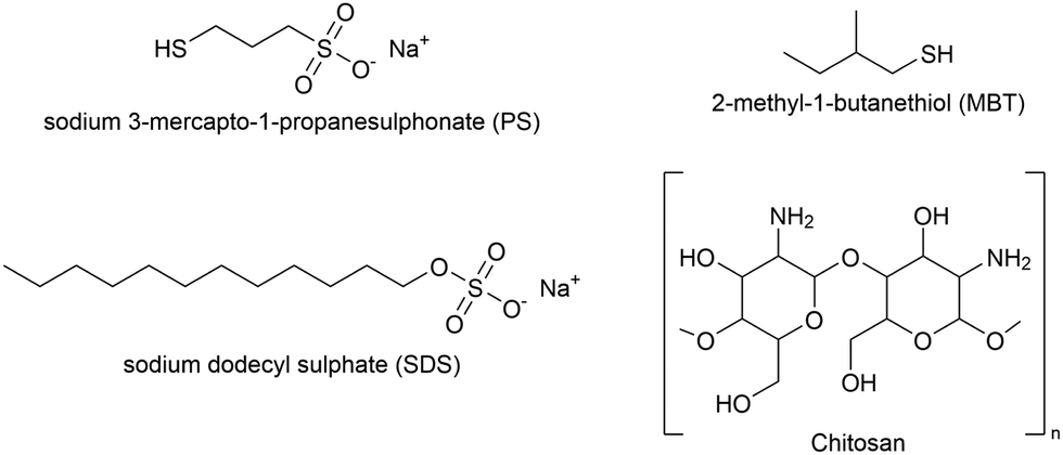 | ||
| Fig. 1 Chemical structures of the molecules used in the adsorption experiments. Top, the thiols (PS and MBT) used to mimic a partially damaged hair surface. Bottom, the anionic surfactant SDS and the polysaccharide chitosan (monomer unit). | ||
2.2. Neutron reflectometry (NR)
Neutron reflectometry allows defining the composition of a layered system along the z-axis, i.e., normal to the surface. Specifically, layer thickness and roughness can be obtained, in addition to the scattering length density (SLD) parameter. The SLD value is calculated from the atomic composition of the layer, and, in the case of adsorption from solutions, it helps to separate the contributions of the solvent and of deuterated and hydrogenous species. The information, however, is averaged in-plane. A detailed theoretical description of the technique can be found in the literature.28,34–37The NR data presented in this paper was obtained from two experiments, one performed at the ISIS Neutron and Muon Source (Oxfordshire, UK) on INTER38 (sequence NR1), and the other one at ILL (Grenoble, France) on the instrument D1739 (sequence NR2). Both instruments are time-of-flight (ToF) reflectometers, so the reflected intensity was recorded as a function of neutron wavelength (λ), and converted as a function of the momentum transfer vector  . On INTER, the incident angles (θ) were set to 0.7° and 2.3°, so to cover a Q-range up to 0.33 Å−1, while on D17 they were set to 0.8° and 3.2° (Q-range up to 0.3 Å−1). Temperature was set at 22 °C. The functionalized gold-coated blocks (with a surface of 50 × 50 and 80 × 50 mm2 for the experiments on INTER and on D17, respectively) were mounted in a solid/liquid cell (Fig. S1 in ESI†). The neutron footprint was controlled to illuminate an area within the liquid trough. The blocks were firstly characterized in GCMW and 100 mM NaCl. GCMW has a neutron SLD of 4.6 × 10⁻⁶ Å−2, similar to gold, and it was chosen because it gives the best contrast to both the hydrogenous thiols and the hydrogenous and deuterated adsorbing species. The adsorption sequences, each performed on a single, separate sample, were the following:
• Sequence NR1:
– 2 and 20 cmc d25-SDS, to check the effect of concentration on adsorption, followed by rinsing to test reversibility;
– 100 ppm chitosan polymer at pH 4, followed by rinsing (at pH 6 as in the other cases);
– 20 cmc d25-SDS, to see how adsorption of SDS changes after exposure of the surface to a cationic species, followed by a final rinsing step;
• Sequence NR2:
– 100 ppm chitosan oligomer, followed by rinsing;
– 2 cmc d25-SDS, to check the effect of the order of injection at the lower SDS concentration (no rinsing was performed after this step);
– A mixture of 100 ppm oligomer and 20 cmc d25-SDS, to see how adsorption changes from a pre-mixed solution compared to sequential injection of the single components. The chitosan/SDS ratio is representative of a (simplified and 10× diluted) shampoo formulation, being 100 ppm chitosan equal to 0.01% w/w and 20 cmc SDS to 1% w/w;4,13
– Final rinsing step.
Data were reduced using the Mantid Workbench40 for INTER and using COSMOS41 for the D17 data, and fitted on RefNX (v. 0.1.32).42 To fit the data in GCMW, a slab model was created to describe the system, then the initial guesses for each layer thickness and roughness, plus the SLD value of the thiol layer, were optimized through a differential evolution algorithm. In the case of INTER data, the background was fitted too as it was not subtracted during data reduction. The validity of the results was checked by running a Markov-Chain Monte Carlo (MCMC) analysis, which returns a covariance matrix and a probability distribution for each parameter.42,43 To run the MCMC analysis, default parameters were used but the number of steps was increased to 5000 and those for burn-in and thinning chains both to 400. After the substrate and thiol layers had been defined, their parameters were fixed so that the successive steps required fitting of the adsorbed layer(s) only. For the latter, no prior assumption was made: if a good fit (firstly by eye then considering the value of Chi2) was not obtained considering one adsorbed layer, a second layer was added; the SLD was fitted in a range chosen to cover the value for the pure substance(s) present in a given step up to the bulk solvent. Values of SLD for the dry substances and their density (used to calculate the SLD on the NIST calculator44) are in Table 1. In the case of chitosan, the density value is taken from ref. 45, but the SLD value is calculated considering that 3 out of the 4 exchangeable protons of each deacetylated monomer exchanged with deuterium (as in GCMW, H/D = 1/3).
| ρ (g mL−1) | SLD (×10−6 Å−2) | |
|---|---|---|
| MBT | 0.85 | −0.25 |
| PS | 1.4 | 1.1 |
| d25-SDS | 1.1 | 6.2 |
| Chitosan | 1.34 | 3.1 |
In order to highlight the adsorbed layer information in fitted SLD profiles we will frequently show the difference in SLD (Δ SLD) between the adsorbed layer and the neat substrate/thiol/solution interface as done previously.30
2.3. Quartz-crystal microbalance (QCM)
Quartz-crystal microbalance (QCM) was used as an independent way of measuring the mass of the adsorbed layer, which can be converted to a thickness by data modeling. The probe is a quartz crystal. Application of a voltage makes the crystal oscillate at its resonance frequency, but the adsorption of material on the crystal causes a shift (Δf) in this frequency, which is proportional to the (hydrated) adsorbed mass (Δm). If there are no changes in the viscoelastic properties of the system, Δm can easily be calculated thanks to the Sauerbrey equation: Δm = −C × Δf/n (C: constant depending on crystal parameters; n: overtone number),46 otherwise more complex models are required.47 A better description of the technique can be found in the literature.48 For the experiments presented here, a Q-sense analyser (Biolin Scientific) was used. This instrument, in addition to the frequency shift, monitors the dissipation energy accompanying the adsorption process (QCM-D). The quartz crystals used for the experiments had a gold coating and a resonance frequency of 5 MHz (OpenQCM). Cleaning involved UV/O3 treatment for 20 min and sonication in solvents of different polarity (acetone, isopropanol, ethanol, MilliQ water, 10 minutes each). The gold surface was first thiolated in situ overnight by injecting in the cell a 1 mM solution of 50:50 MBT:PS in ethanol. Adsorption of polymeric and oligomeric chitosan and their mixtures with SDS was then studied at 22 °C, using as solvent 100 mM NaCl in MilliQ water, similarly to NR experiments (but h-SDS was used instead of d25-SDS). Specifically, three QCM experiments were performed, each one in duplicate on separate substrates (unless specified, solutions and rinsing steps were at pH 6):
• Sequence QCM1:
– 100 ppm chitosan oligomer, followed by rinsing.
– 100 ppm chitosan polymer (pH 4) to check competition/effect of molecular weight, followed by rinsing.
– 100 ppm polymer and 20 cmc SDS (pH 4) to check the effect of SDS, followed by rinsing (here the sample was left overnight in 100 mM NaCl to verify whether desorption was slow or irreversible).
– 100 ppm oligomer and 20 cmc SDS to check competition/effect of molecular weight, followed by rinsing.
• Sequence QCM2:
– 100 ppm chitosan polymer (pH 4) to compare adsorption on a clean surface to the step in sequence QCM1, followed by rinsing (pH 4).
– 20 cmc SDS to compare adsorption to the mixture on sequence QCM1, followed by rinsing.
• Sequence QCM3:
– 2 cmc SDS, 20 cmc SDS, rinsing – to check the adsorption of SDS on a clean surface, as done in sequence NR1 (Section 2.2).
– 100 ppm chitosan oligomer to compare adsorption to sequence QCM1, followed by rinsing.
– 2 cmc SDS to compare to the previous step before chitosan.
– 20 cmc SDS and 100 ppm oligomer as done in sequence NR2 (Section 2.2), followed by rinsing.
Data analysis was carried out using the software QTools (Biolin Scientific), applying a one-layer Maxwell model49 and considering, for the solvent, density and viscosity values of water in the presence of 100 mM NaCl.50 (For diluted chitosan/SDS solutions, the variation in bulk density and viscosity has been reported to be negligible.51,52) No reliable fit could be obtained for sequence QCM3 (even using other models47,48), so the results can only be used for qualitative comparison to the NR data.
2.4. Atomic force microscopy (AFM)
AFM measurements were performed in liquid on a Dimension Icon (Bruker), in PeakForce QNM (Quantitative Nanomechanics) mode, using ScanAsyst Air tips from Bruker. The 50:50 MBT:PS sample was produced in triplicate using template-stripped gold surfaces (Platypus Technologies). AFM images were acquired in 100 mM NaCl, then the solution was replaced first by one containing 100 ppm of low molecular weight chitosan (oligomer) and then by 20 cmc SDS. Before use, solutions were filtered using a 0.2 μm syringe filter. At each adsorption step, three different spots on the surface were imaged, acquiring 2–3 images for each spot (scan size 5 μm, 256 pixels). AFM images were analysed using the software Gwyddion,53 while those presented in the next section were visualised using MountainsSPIP (Digital Surf).
3. Results and discussion
In this section, the characterization of the mixed thiol layer is presented, followed by the study of adsorption of chitosan and SDS. It was chosen to discuss the results of NR, QCM and AFM experiments in terms of the adsorbing species rather than following the order of the adsorption sequences listed in the previous section. Chitosan, the most interesting species from an applicative perspective, is discussed first since most of the experiments start with its adsorption, the only exception being sequence NR1. The adsorption of SDS follows, with a discussion on the order of injection of surfactant and polysaccharide. Finally, adsorption of a pre-mixed SDS/chitosan complex is presented.3.1. Mixing of thiols
Fig. 2(a) shows the NR data obtained for the two samples produced. Fitting of these curves gives the SLD profiles in Fig. 2(b).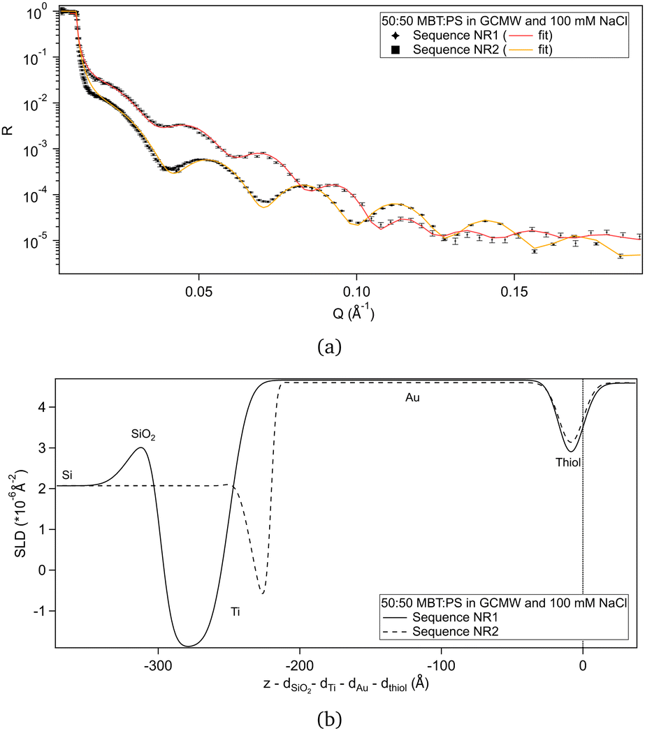 | ||
| Fig. 2 (a) NR curves for the two samples of 50:50 MBT:PS, with best fit lines. Error bars are shown on the data points. Differences in reflectivity are mainly due to the different characteristics of the gold-coated substrates. (b) Corresponding SLD profiles. The layers considered in the slab model are indicated. In the case of the substrate used in sequence NR2, there was some mixing of the Ti and SiO2 layers, as shown by the less defined peaks in the profile. The zero on the x-axis is placed at the thiol/solution interface, so that the portions of the profiles relative to the thiol layer are aligned despite differences in the substrates. | ||
The difference in the profiles at the left of the graph are clearly due to the different substrates: the one used in sequence NR1 has a defined native oxide layer just on top of silicon, and thicker deposited layers of titanium and gold. Nevertheless, the overlap of the SLD profiles just below x = 0 indicates that the two thiol layers are similar, and the fitted parameters (Table 2) are in agreement, within error. According to values in Table 1, a 50:50 mixture of MBT and PS would lead to a layer of SLD ≈ 0.4 × 10⁻⁶ Å−2, so the fitted SLDs in Table 2 indicate that, for both samples, either the thiol layers contain some water of hydration, or that PS adsorbed preferentially over MBT, or both. An independent XPS analysis was performed, leveraging the different binding energies of the two types of sulphur groups.54 It indicates that the average composition was in fact 50:50 (see Section S2 in the ESI†), suggesting that hydration of the sulphonates is responsible for the slightly elevated fitted SLD value in solution. Note though that a certain degree of heterogeneity or variability is to be expected as the layer formation is influenced by multiple factors.31
:50 MBT:PS samples. The error in parenthesis corresponds to 2.5σ
| Thiol layer | Thickness (Å) | SLD (×10−6 Å−2) |
|---|---|---|
| Sequence NR1 | 9 (2) | 0.5 (0.9) |
| Sequence NR2 | 9.00 (0.01) | 0.95 (0.03) |
The thickness obtained by fitting the NR data is slightly higher than previously found for the pure MBT and PS surfaces,30 suggesting the formation of upright chains and the presence of bound water/counterions to the sulphonate moiety.55 As the thiol samples were not measured in another solvent with different contrast, it is not possible to define the relative amount of each component from the NR experiments. Considering that the MBT:PS ratio is the expected one, as suggested by XPS, the hydration percentage would be 2% and 13% for sequence NR1 and sequence NR2, respectively.
3.2. Adsorption of chitosan
The adsorption of chitosan of two molecular weights was studied by NR. Specifically, a 3 kDa molecule (referred to as “oligomer”) was used in sequence NR2 and a 27 kDa molecule (i.e., the “polymer”) in sequence NR1 (see experimental sequences in Section 2.2). It is to be noted that the latter was not adsorbed on a virgin surface but after exposure of the sample to d25-SDS, whose effect is presented in Section 3.3. Results from fitting of NR data relative to chitosan and following rinses are shown in Fig. 3, as depth profiles from which the substrate/solution SLD profiles (Fig. 2b) have been subtracted. The x-axis has its zero at the thiol/adsorbed layer interface, as in the previous graph, but the y-axis indicates the variation of SLD values compared to the substrate/solution interface upon adsorption (as done in our previous study30). The fitted reflectivity curve and the full SLD profiles can be found in Fig. S8, S9, S15 and S16 in the ESI† (the same applies to the other NR data presented in the following sections). Fitted parameters are in Table 3.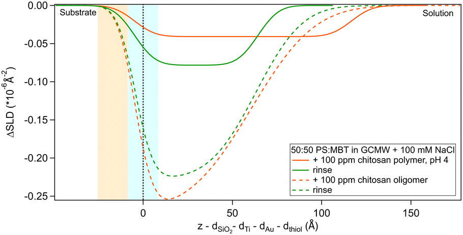 | ||
| Fig. 3 Subtracted SLD profiles of chitosan (in orange), oligomer (dashed line) and polymer (full line), adsorbed on 50:50 MBT:PS. Corresponding rinses are shown in green. The zero of the x-axis is at the thiol/chitosan interface, whose roughness is indicates by the blue panel. Similarly, the yellow panel on the left represents the Au/thiol interface with its associated roughness. | ||
:50 MBT:PS samples. The error in parenthesis corresponds to 2.5σ. The number in italics were fixed
| SLD (×10−6 Å−2) | Thickness (Å) | Roughness (Å) | |
|---|---|---|---|
| Oligomer | 4.21 (0.01) | 65 (3) | 28 (3) |
| Oligomer rinse | 4.41 (0.01) | 68 (2) | 21 (3) |
| Polymer | 4.56 (0.03) | 121 (51) | 9 |
| Polymer rinse | 4.52 (0.03) | 69 (15) | 9 |
The layer formed by the chitosan oligomer is about 60 Å thick but is not well-defined, considering the large value of the roughness. On rinsing, the thickness stays the same and the SLD slightly increases, indicating that only little material is removed. It is possible to calculate a surface excess (Γ) of the oligomer from the fitted SLD values, by multiplying oligomer volume fraction ϕ = (SLDsolvent − SLDlayer)/(SLDsolvent − SLDdrymolecule), layer thickness τ and chitosan density ρ, according to the equation Γ = ϕ × τ × ρ/MW (dividing by the molecular weight MW gives Γ in terms of mol cm−2).56,57 By applying this formula, the oligomer has a surface excess of 1.1 nmol cm−2 (in terms of monomer units, i.e., MW = 162 g mol−1), reduced to 0.8 nmol cm−2 after rinsing. The volume fraction of water in the layer, then, increases from 80% to 85%. Such high hydration levels are in agreement with literature.20 AFM results indicate that the oligomer adsorbs as separate aggregates on the surface. Examples of AFM images in 100 ppm oligomer solution are in Fig. 4. As the two images show, the surface is quite heterogeneous. Particle coverage varies from 13% (Fig. 4a) to 3% (Fig. 4b), and particle height from 1 to several tens of nm, with a median value of ≈3.5 nm. Direct comparison of particle heights from AFM with effective thicknesses from our surface techniques is not straightforward, as has been pointed out for example by Dhopatkar et al.58 Briefly, height thresholds to define individual particles for software recognition need to be defined, AFM images are small and not necessarily globally representative, (see Fig. 4) and are defined in terms of the median value, so particle size distributions can affect the resulting value. Nevertheless, AFM was useful to add topographical information that can be obtained neither with NR nor QCM, and emphasises that the slab interpretations, while capturing the amounts and degrees of hydration, can be intuitively misleading from in-plane averaging. (This may suggest the use of different models to fit the NR data, such as applying a mixed area model that considers the system as the sum of two structures. This approach was eventually rejected due to neutron coherence volume arguments – more details in Section S5 in the ESI.†)
 | ||
| Fig. 4 AFM images of chitosan oligomer adsorbed on 50:50 MBT:PS surfaces at two different positions (a, b) on the same sample. The detected particles are coloured in green. | ||
Regarding the polymer, the layer it forms is more difficult to describe precisely, due to the poor contrast with the bulk solution. The layer roughness was fixed as it could not be defined by fitting. The closeness of the layer SLD to the bulk can be due to a higher hydration but also to the presence of residual d25-SDS from the previous adsorption steps. For this reason, it is not possible to calculate the surface excess of polymer. Rinsing causes the layer to condense: thickness and SLD both decrease, indicating an increase in the volume fraction of chitosan in the adsorbed layer. It is useful to remind here that, while the solution of polymer is at pH 4, the rinse is done at pH 6. The known poor solubility of chitosans of high MW at higher pH, added to enthalpy considerations (e.g., electrostatic interactions) that caused adsorption from the bulk in the first place, can explain the preferential interaction of the polymer with the surface when rinsing. This is in line with previous literature findings on the effect of pH on the properties of chitosan.59,60
Adsorption of chitosan was also studied by QCM-D (see Section 2.3). The fitted experimental curves are shown in Fig. 5 and 6. The discussion is here limited to the first steps in the graph, the effect of SDS will be described in the next sections.
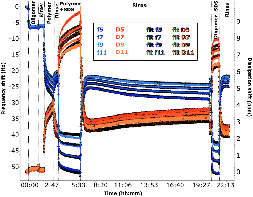 | ||
| Fig. 5 QCM-D data for adsorption on 50:50 MBT:PS (sequence QCM1). The adsorption sequence is indicated on the graph. The pH is ≈6 for all the solutions except those containing the polymer. Frequency shifts are shown in blue and dissipation in red, for the overtones specified in the legend. The darker plots are the corresponding fits. | ||
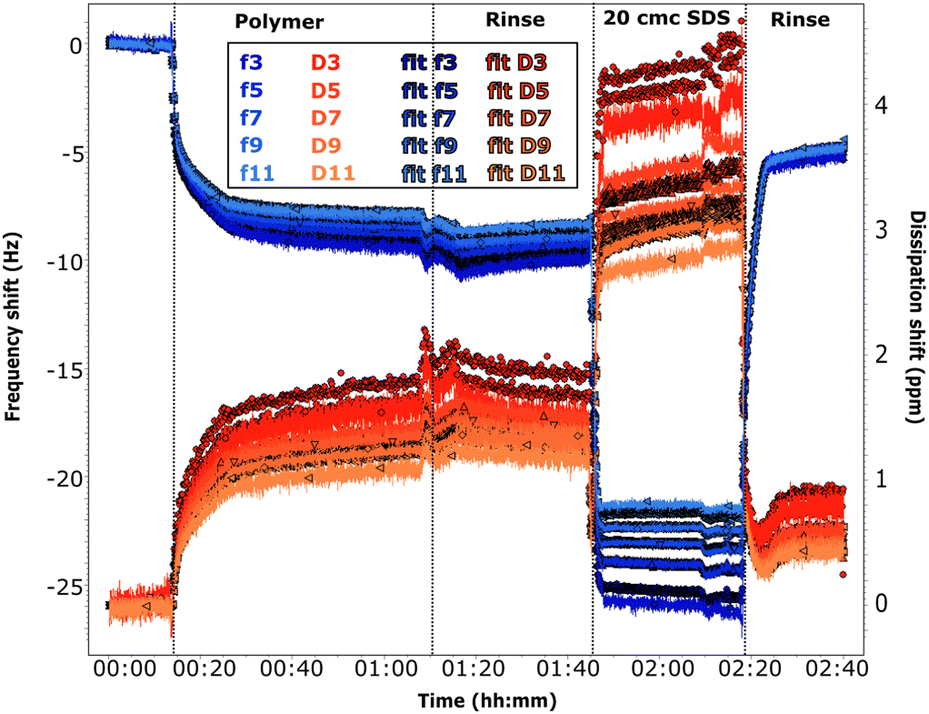 | ||
| Fig. 6 QCM-D data for adsorption on 50:50 MBT:PS (sequence QCM2). The adsorption sequence is indicated on the graph. The pH is ≈6 at the beginning, for the solution of SDS and for the final rinse. It is 4 in the case of the polymer solution and its rinse. Frequency shifts are shown in blue and dissipation in red, for the overtones specified in the legend. The darker plots are the corresponding fits. | ||
The frequency shifts due to adsorption of the oligomer in Fig. 5 and of the polymer in Fig. 6 reach quickly their plateau value. In the case of the polymer in Fig. 5, its adsorption is slower and overtones are more spread. This different behaviour is likely caused by the presence of the oligomer previously adsorbed in sequence QCM1, which modifies the interactions on the surface. Neither the oligomer (Fig. 5) nor the polymer (Fig. 5 and 6) are removed by rinsing, in agreement with NR results. In the case of the polymer, rinsing at pH 6 (Fig. 5) causes a slight reduction in the frequency shift but it is accompanied by a large variation in dissipation. This suggests that there are variations in the viscoelastic properties of the adsorbed layer more than desorption of the polymer, which is compatible with NR findings of a condensed polymer layer upon rinsing. This is also in line with literature data.60 (However, from QCM data only, one cannot rule out the possibility of some desorption of chitosan as the two species, oligomer and polymer, compete for adsorption.) Data fitting indicates that the oligomer adsorbs in a 80 Å thick layer (±10 Å), which slightly decreases to ≈60 Å after rinsing. The polymer, when injected after the oligomer, increases the thickness of the adsorbed layer to ≈450 Å (≈300 Å after rinsing at pH 6). Instead, in sequence QCM2 it forms a ≈270 Å thick layer (not affected by the rinse at pH 4). In general, thickness values obtained by QCM are higher than those found by NR, as the former measures mass, while NR is capable of isolating the contribution of the adsorbed species.
3.3. Adsorption of SDS
Regarding the surfactant, its adsorption was studied at different concentrations and before and after chitosan adsorption. On a clean surface, d25-SDS adsorbs as a hydrated monolayer from a 2 cmc solution. Increasing the concentration 10 times results in almost no change in the adsorbed amount, as shown in Fig. 7.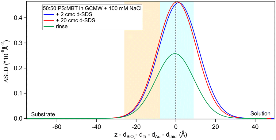 | ||
| Fig. 7 Subtracted SLD profiles of d25-SDS adsorbed on 50:50 MBT:PS, at the concentrations indicated on the graph and after rinsing. The zero of the x-axis is at the thiol/d25-SDS interface, whose roughness is indicates by the blue panel. Similarly, the yellow panel on the left represents the Au/thiol interface with its associated roughness. | ||
The rinse removes part of the adsorbed SDS. It has to be noted that d25-SDS was used as received, so, even though solutions were freshly prepared just before the experiment, it is likely to contain some dodecanol, which is a known contaminant of SDS,61 but it was considered important to work with industrially relevant samples.
Fitted values for SLD, thickness and surface excess of d25-SDS are presented in Table 4. As previously in the case of chitosan polymer, the roughness values had little effect on the fit. For this reason, roughness was fixed to 9 Å, to follow that of gold and consequently of the thiol surface.
:50 MBT:PS sample. The error in parenthesis corresponds to 2.5σ
| Clean surface | SLD (×10−6 Å−2) | Thickness (Å) | Γ (nmol cm−2) |
|---|---|---|---|
| 2 cmc d25-SDS | 5.4 (0.3) | 13 (4) | 0.22 |
| 20 cmc d25-SDS | 5.6 (0.5) | 11 (5) | 0.25 |
| Rinse | 5.3 (0.7) | 9 (8) | 0.13 |
According to Table 4, there is a very slight increase in the adsorbed amount of d25-SDS when increasing the concentration in solution to 20 cmc. The calculated surface excess is about half of the value obtained for adsorption of SDS on pure MBT,30 which correlates well with the presence of 50% PS in the thiol layer. It has been reported that the density of cysteic acid, and thus of sulphonate moieties, on the surface of bleached hair is 2.8 molecules nm−2, the sulphonate group having a lateral length of 2.5 Å.11 The density of a SAM of simple alkyl thiols is typically ≈4.5 molecules nm−2,31 but in this mixed-surface model the sulphonate group of PS and the methyl branch of MBT require both a larger area per molecule, so that the density is likely closer to the value on bleached hair. Converting the surface excess of the adsorbed d25-SDS in terms of molecules nm−2, densities are 1.3, 1.5 and 0.8 molecules nm−2 for 2 cmc, 20 cmc and rinsing step, respectively. This rough estimate corroborates the idea of SDS molecules interacting with the hydrophobic groups on the model surface. The thickness of the adsorbed SDS is compatible with a tilted monolayer, as the SDS chain length is 17 Å.62 The rinse then removes about half of the adsorbed amount; though it should be noted that the error on this fit is significantly higher than in the previous steps, so the calculated surface excess is less reliable in this case. The frequency data from QCM confirms the observation from Fig. 7, as the frequency shift upon changing from 2 cmc SDS to 20 cmc SDS is negligible (see Fig. S3 in the ESI†). It can be noted that, as reported previously for high SDS concentrations,30 the dissipation increases, and there is less agreement between overtones. This behaviour is maintained upon rinsing, while the frequency shift returns to almost zero. This renders the fitting (of any conventional model) more challenging, so it should be at best considered semi-quantitatively. Nonetheless, the Sauerbrey equation46 can be applied, though only to the data from the adsorption of 2 cmc SDS. According to this, the adsorbed mass is ≈200 ng cm−2 (SDS plus bound water). The surface excess of 2 cmc d25-SDS shown in Table 4 corresponds to 70 ng cm−2; the volume fraction of solvent in the layer is 46%, and thus a mass of 60 ng cm−2 for a total of 130 ng cm−2. This is quite a rough estimate based on a density of 1 g cm−3 (the actual value is likely to be higher due to the presence of D2O and salt in the bulk solution). Considering also the uncertainty associated to the Sauerbrey mass, the two values for the adsorbed hydrated mass are reasonably in agreement.
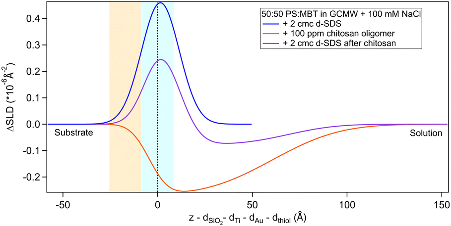
The situation is different when SDS adsorbs on a surface previously exposed to chitosan. The results by NR are in Fig. 8 and 9. Both figures show the depth profiles relative to adsorption of SDS before and after injection of chitosan. The corresponding profiles for chitosan are added. For the polymer, the profile after rinsing was used as this is more representative of the layer present when the SDS injection occurred, and is additionally at the same pH.
 | ||
| Fig. 8 Subtracted SLD profiles of 2 cmc d25-SDS adsorbed on 50:50 MBT:PS, before (same as Fig. 7) and after injection of chitosan oligomer. For comparison, the profile corresponding to pure chitosan (same as Fig. 3) is added. The zero of the x-axis is at the thiol/d25-SDS interface, whose roughness is indicated by the blue panel. Similarly, the yellow panel on the left represents the Au/thiol interface with its associated roughness. | ||
 | ||
| Fig. 9 Subtracted SLD profiles of 20 cmc d25-SDS adsorbed on 50:50 MBT:PS, before (same as Fig. 7) and after injection of chitosan polymer. For comparison, the profile corresponding to the polymer layer after rinsing (same as Fig. 3) is added. The zero of the x-axis is at the thiol/d25-SDS interface, whose roughness is indicates by the blue panel. Similarly, the yellow panel on the left represents the Au/thiol interface with its associated roughness. | ||
Regarding 2 cmc d25-SDS, it adsorbs close to the surface, causing an increase in SLD, compared to the oligomer, to an extent compatible with a monolayer of SDS. The data is best fitted with a two-layer model (see Table 5).
:50 MBT:PS samples exposed to chitosan. The error in parenthesis corresponds to 2.5σ. The values in italics were fixed
| After chitosan | SLD (×10−6 Å−2) | Thickness (Å) | Roughness (Å) |
|---|---|---|---|
| 2 cmc d25-SDS | 5.15 (0.09) | 13 (2) | 10 |
| 4.56 (0.01) | 61 (10) | 20 | |
| 20 cmc d25-SDS | 5.7 (0.2) | 29 (4) | 10 (5) |
The first adsorbed layer has a lower SLD than pure SDS, which can be explained by contrast matching of a fraction of SDS to chitosan. The second layer is formed by the remaining chitosan extending towards the bulk solution. The contrast being poor, the error on the fitted parameters is higher, but the total thickness of the adsorbed layers is compatible with the thickness of the adsorbed (pure) oligomer (Table 3). Again, roughness was fixed as it could not be precisely determined by fitting. QCM data (Fig. S3 in the ESI†) qualitatively agree with NR as the frequency shift of lower order overtones is close to that for 2 cmc SDS adsorbed on a virgin surface (despite dissipation being larger – the complex viscoelastic behaviour of polyelectrolyte/surfactant mixtures is known in the literature, see e.g., ref. 51 and 58).
AFM images indicate a decrease in the area covered by particles, as Fig. 10 shows. Particle coverage is 4% in Fig. 10a and 0.8% in Fig. 10b. The maximum particle height increases to about 100 nm, with an average of ≈4.5 nm. The apparent decrease in adsorbed particles might be an artefact, as the adsorbed surfactant can be masking the smaller particles of chitosan by forming a relatively homogeneous layer.
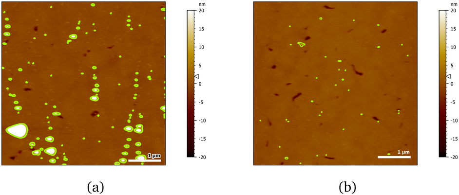 | ||
| Fig. 10 AFM images of 20 cmc SDS adsorbed after chitosan oligomer on 50:50 MBT:PS surfaces at two different positions (a, b). The detected particles are coloured in green. | ||
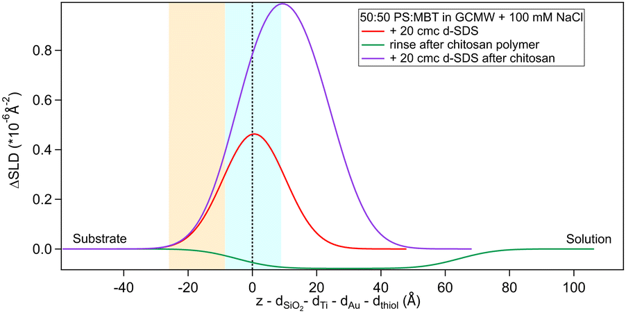
The higher concentration of 20 cmc adsorbed after the polymer in sequence NR1, instead, resulted in the formation of one layer, thicker than a monolayer of SDS molecules. The fitted SLD is almost at the value for SDS adsorbed to pure MBT,30 but here the amount of SDS appears to be mixed with the polymer and distributed further from the surface (see schematic in Fig. 11). Rinsing the surface removed most of the adsorbed species: no adsorbed layer was required in the fitting model but the slab corresponding to the thiol layer was fitted again. It resulted in a slightly larger thickness of 10 ± 1 Å and SLD of 1.7 (±0.3) × 10−6 Å−2, suggesting some residues stayed on the surface. This seems to agree with QCM results (Fig. 6): the thickness of the adsorbed SDS layer does not change compared to the pure polymer, but the fitted viscosity varies from 1.09 to 1.26 mPa s (for reference, water has a viscosity of 0.9 mPa s at 25 °C (ref. 58)). After rinsing, thickness decreases to ≈150 Å, while viscosity goes back to 1.09 mPa s. These results can be interpreted as SDS interacting with the chitosan layer and being preferentially removed upon rinsing. The rinse before injection of SDS was at pH 4, while the final one is at pH 6, and, as seen in the previous section, the decrease in thickness can also indicate a condensation of the residual layer due to the variation of pH. As, differently from Fig. 3, no adsorbed layer is detected by NR upon rinsing, it can be argued that weakly bound chitosan is also desorbed with SDS. The absence of an additional slab on the thiol surface in the NR model, anyway, does not rule out the possibility of irreversibly adsorbed residues in this case: considering the SLDs of the involved species, the contrast between the residual layer and the bulk solution may be too poor to be reliably modelled, and it appears just as a slight variation of the thiol layer.
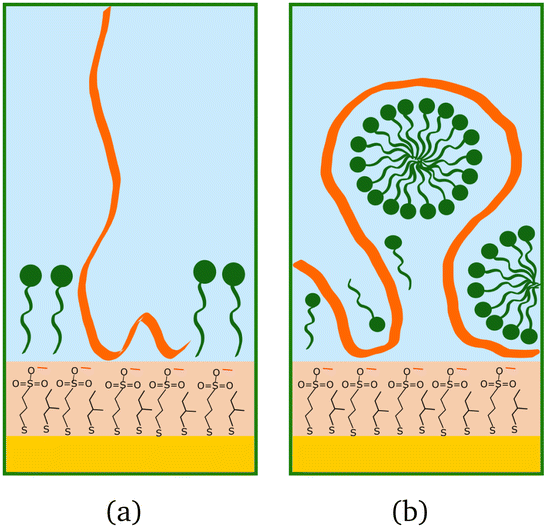 | ||
| Fig. 11 Schematic drawings of SDS (green) adsorbed after chitosan (orange): (a) oligomer, (b) polymer. | ||
3.4. Adsorption of a chitosan/SDS complex
As a final step, the adsorption of a pre-mixed solution of 20 cmc d25-SDS and 100 ppm chitosan oligomer was studied. As mentioned in Section 2.2, this surfactant/polyelectrolyte ratio is representative of that in a cosmetic formulation.4,13 Results are in Fig. 12 and Table 6.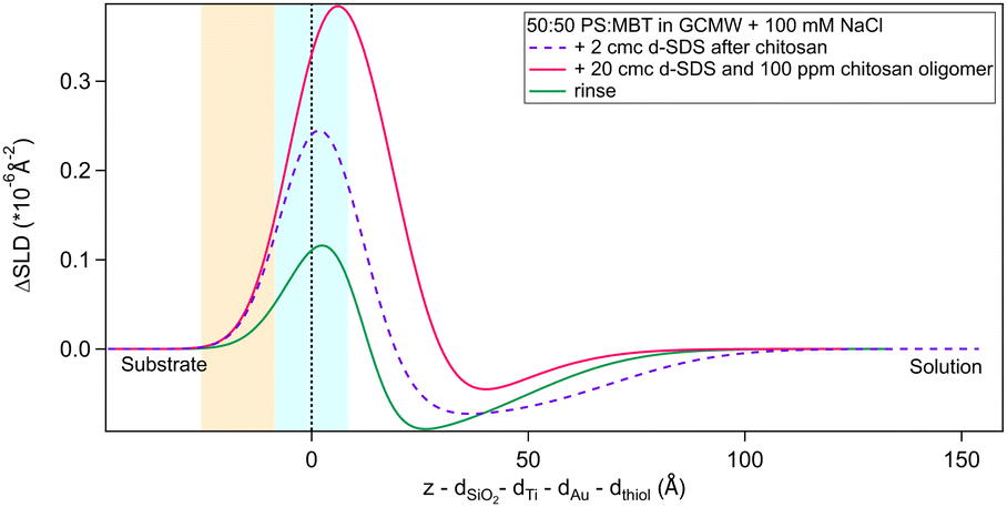 | ||
| Fig. 12 Subtracted SLD profiles of a pre-mixed d25-SDS/chitosan complex adsorbed on 50:50 MBT:PS (magenta line), and the following rinse (green). For comparison, the profile corresponding to the same molecules adsorbed in successive steps (same as Fig. 8) is added (dashed line). The zero of the x-axis is at the thiol/d25-SDS interface, whose roughness is indicates by the blue panel. Similarly, the yellow panel on the left represents the Au/thiol interface with its associated roughness. | ||
:50 MBT:PS samples from a premixed solution. The error in parenthesis corresponds to 2.5σ. The values in italics were fixed
| SLD (×10−6 Å−2) | Thickness (Å) | Roughness (Å) | |
|---|---|---|---|
| d25-SDS/chitosan | 5.13 (0.03) | 23 (10) | 10 |
| 4.52 (0.07) | 20 (11) | 20 | |
| Rinse | 4.81 (0.03) | 16 (2) | 6.2 (0.7) |
| 4.53 (0.03) | 37 (12) | 20 (6) |
The structure of the adsorbed d25-SDS/oligomer complex is reminiscent of that of the two components added sequentially. The total thickness is conserved, within error, and again one layer can be defined closer to surface and enriched in d25-SDS, and one layer formed of excess chitosan extending towards the bulk solution. In this case, though, similarly to d25-SDS adsorbed after chitosan polymer, the SDS-rich layer is thicker than the molecular length, suggesting that SDS molecules interact with chitosan and distribute over a larger distance. Rinsing removes only part of the adsorbed layers, and considering the SLD of the residual layers, it can be argued that SDS is preferentially, even though not completely, removed. QCM results (last steps in Fig. 5) indicate a thicker layer of about 500 Å, but here the oligomer/SDS complex is adsorbed after a polymer/SDS complex, that reached the same thickness. After both rinsing steps, a residual layer of ≈300 Å is left on the surface, the same as after the pure polymer. This suggests that, when injecting the oligomer/SDS complex, the mixture may compete with residual polymer to adsorb to the surface, so the adsorbate structure will be different from the one observed by NR.
4. Conclusions
This study aimed primarily to describe adsorption of SDS and chitosan on a mixed thiol surface. As the surface film is formed by a hydrophobic thiol and a sulphonate-terminated one, it thus mimics the surface of an hair fibre whose lipid layer has been partly removed. NR data, complemented by QCM and AFM measurements, show interesting details about the interaction properties of this model surface, the differences between the different chitosan samples, and their interaction with surfactant:1. SDS is able to adsorb on the surface, likely interacting with the hydrophobic moieties that form ≈50% of the thiol layer. Its surface excess is, in fact, 0.22 nmol cm−2, a value corresponding to about a half of that found on the pure hydrophobic thiol,30 and it does not increase when increasing SDS concentration in the bulk;
2. Both the oligomeric and the polymeric forms of chitosan adsorb on the surface, which NR and QCM interpret as highly hydrated layers, but which AFM clarifies as formed by isolated aggregates spread on the surface. These two views of the interface are entirely compatible. NR provides an integration over sample areas of the order of square centimetres in lateral dimensions, with exquisitely detailed information on the nm scale in the surface normal direction. AFM reveals the discrete nature of the adsorption. While it is not possible to define the exact quantities, NR data seem to suggest that the amount of adsorbed oligomer is bigger than the polymer, in terms of monomer units. Both the polymer and oligomer adsorb irreversibly, in the case of the polymer a certain degree of consolidation of the layer occurs on rinsing, as the pH is raised, reflecting the internal electrostatics of the adsorbate.
3. Adsorption of SDS increases in the presence of preadsorbed chitosan, but the structures are different depending on the type of chitosan. More SDS adsorbs to the polymer and has the effect of significantly collapsing the layer thickness, consistent with electrostatic arguments but with SDS detectable at greater distance from the surface than is the case with the oligomer. Upon rinsing, SDS is preferentially desorbed, leaving a residue which is likely mostly composed of chitosan. In the case of the polymer it would appear that weakly adsorbed chitosan is desorbed, which reduces the dissipation significantly in QCM, but the majority of the adsorbed material remains.
4. When chitosan oligomer and SDS were allowed to adsorb from a mixture, instead of sequentially, rather different behaviour was observed. Considerably more SDS was observed in the surface film, extending to larger distances from the surface, though once again two regions were observed with a more dilute chitosan fraction at larger distance. The overall film thickness remains the same.
These findings are of interest in a cosmetic perspective: the system mimics a “partially damaged” hair surface, which is probably the most common situation when looking at consumers' needs but only a few attempts have been made so far to model it. The different behaviour of chitosan depending on its molecular weight is of particular importance, it being a bio-sourced ingredient, and thus relevant for sustainability concerns.
This hair model, though, is still rather simple as it does not consider the mismatch in length between hydrophobic and sulphonate moieties, which is a feature of the real surface. Future studies will incorporate the length mismatch, and employ more biomimetic hydrophobic species.
Data availability
Neutron reflectometry data for this article are available at the following repositories: data collected on the instrument INTER at ISIS Neutron and Muon Source (UK): https://doi.org/10.5286/ISIS.E.RB2210338 (referred to as sequence NR1 in the paper). Data collected on the instrument D17 at ILL (France): https://zenodo.org/doi/10.5281/zenodo.13684104 (referred to as sequence NR2 in the paper) Quartz-crystal microbalance supporting data are included in the second repository.Conflicts of interest
The authors declare the following competing financial interest: G. S. L., A. G. and F. Z. are full employees of L'Oréal involved in research activities.Acknowledgements
This project has received funding from the European Unions Horizon 2020 research and innovation programme under the Marie Skłodowska-Curie grant agreement no. 847439. Experiments at the ISIS Neutron and Muon Source were supported by a beamtime allocation RB2210338 from the Science and Technology Facilities Council. We acknowledge beam time on the D17 reflectometer provided by ILL, and the Partnership for Soft Condensed Matter (PSCM) at ILL for providing access to the QCM-D instrumentation. M. R. and S. C. thank the Swedish Research Council (VR) for support via grant 2022-04614. We thank L'Oréal, and in particular Anne-Claude Dublanchet and the Imaging Unit headed by Thomas Bornschloegl, for their support to the project and the use of the AFM instrument.References
- S. Breakspear, J. R. Smith and G. Luengo, J. Struct. Biol., 2005, 149, 235–242 CrossRef PubMed
.
- S. Tokunaga, H. Tanamachi and K. Ishikawa, Cosmetics, 2019, 6, 31 CrossRef
- H. Tanamachi, S. Tokunaga, N. Tanji, M. Oguri and S. Inoue, J. Cosmet. Sci., 2010, 61, 147–160 CAS
- G. S. Luengo, A.-L. Fameau, F. Leonforte and A. J. Greaves, Adv. Colloid Interface Sci., 2021, 290, 102383 CrossRef CAS PubMed
- C. J. Thompson, N. Ainger, P. Starck, O. O. Mykhaylyk and A. J. Ryan, Macromol. Chem. Phys., 2023, 224, 2200420 CrossRef CAS
- D. J. Peet, R. E. Wettenhall, D. E. Rivett and A. K. Allen, Comp. Biochem. Physiol., Part B: Biochem. Mol. Biol., 1992, 102, 363–366 CrossRef CAS PubMed
- P. W. Wertz and D. T. Downing, Lipids, 1988, 23, 878–881 CrossRef CAS PubMed
- L. N. Jones and D. E. Rivett, Micron, 1997, 28, 469–485 CrossRef CAS PubMed
- D. A. Csuka, E. A. Csuka, M. L. Juhász, A. N. Sharma and N. A. Mesinkovska, Int. J. Dermatol., 2023, 62, 404–415 CrossRef PubMed
- S. Thibaut, E. De Becker, B. Bernard, M. Huart, F. Fiat, N. Baghdadli, G. Luengo, F. Leroy, P. Angevin and A. Kermoal,
et al.
, Int. J. Cosmet. Sci., 2010, 32, 422–434 CrossRef PubMed
- M. Korte, S. Akari, H. Kühn, N. Baghdadli, H. Möhwald and G. S. Luengo, Langmuir, 2014, 30, 12124–12129 CrossRef PubMed
- H. Mizuno, G. S. Luengo and M. W. Rutland, Langmuir, 2010, 26, 18909–18915 CrossRef PubMed
- P. A. Cornwell, Int. J. Cosmet. Sci., 2018, 40, 16–30 CrossRef PubMed
- M. Philippe, B. Didillon and L. Gilbert, Green Chem., 2012, 14, 952–956 RSC
- G. Luengo, F. Léonforte, A. Greaves, R. Rubio and E. Guzmán, Green Chem., 2023, 25, 7863–7882 RSC
- N. Baghdadli, G. S. Luengo and L. Recherche, J. Phys., 2008, 100, 052034 Search PubMed
- H. Mizuno, G. S. Luengo and M. W. Rutland, Langmuir, 2013, 29, 5857–5862 CrossRef PubMed
- Z. Besharat, D. Wakeham, C. M. Johnson, G. S. Luengo, A. Greaves, I. Odnevall Wallinder, M. Göthelid and M. W. Rutland, J. Colloid Interface Sci., 2016, 484, 279–290 CrossRef PubMed
- L. Fernández-Peña, E. Guzmán, F. Leonforte, A. Serrano-Pueyo, K. Regulski, L. Tournier-Couturier, F. Ortega, R. G. Rubio and G. S. Luengo, Colloids Surf., B, 2020, 185, 110578 CrossRef PubMed
- M. Hernández-Rivas, E. Guzmán, L. Fernández-Peña, A. Akanno, A. Greaves, F. Léonforte, F. Ortega, R. G. Rubio and G. S. Luengo, Colloids Interfaces, 2020, 4, 33 CrossRef
- E. Guzmán, F. Ortega, N. Baghdadli, C. Cazeneuve, G. S. Luengo and R. G. Rubio, ACS Appl. Mater. Interfaces, 2011, 3, 3181–3188 CrossRef
- E. Guzmán, F. Ortega, N. Baghdadli, G. S. Luengo and R. G. Rubio, Colloids Surf., A, 2011, 375, 209–218 CrossRef
- E. Guzmán, S. Llamas, L. Fernández-Peña, F. Léonforte, N. Baghdadli, C. Cazeneuve, F. Ortega, R. G. Rubio and G. S. Luengo, Colloids Surf., A, 2020, 585, 124178 CrossRef
- B. J. Coscia, J. C. Shelley, A. R. Browning, J. M. Sanders, R. Chaudret, R. Rozot, F. Léonforte, M. D. Halls and G. S. Luengo, Phys. Chem. Chem. Phys., 2023, 25, 1768–1780 RSC
- S. Banerjee, C. Cazeneuve, N. Baghdadli, S. Ringeissen, F. Léonforte, F. A. Leermakers and G. S. Luengo, J. Phys. Chem. B, 2017, 121, 8638–8651 CrossRef PubMed
- T. I. Morozova, N. A. García, J.-L. Barrat, G. S. Luengo and F. Léonforte, ACS Appl. Mater. Interfaces, 2021, 13, 30086–30097 CrossRef PubMed
- S. Llamas, E. Guzmán, F. Ortega, N. Baghdadli, C. Cazeneuve, R. G. Rubio and G. S. Luengo, Adv. Colloid Interface Sci., 2015, 222, 461–487 CrossRef PubMed
- J. Penfold, Curr. Opin. Colloid Interface Sci., 2002, 7, 139–147 CrossRef CAS
- E. Guzmán, F. Ortega and R. G. Rubio, Cosmetics, 2022, 9, 99 CrossRef
- S. Cozzolino, P. Gutfreund, A. Vorobiev, A. Devishvili, A. Greaves, A. Nelson, N. Yepuri, G. S. Luengo and M. W. Rutland, Soft Matter, 2024, 20, 7634–7645 RSC
- J. C. Love, L. A. Estroff, J. K. Kriebel, R. G. Nuzzo and G. M. Whitesides, Chem. Rev., 2005, 105, 1103–1170 CrossRef PubMed
-
P. Mukerjee, Critical micelle concentrations of aqueous surfactant systems, NBS Publications, 1971 Search PubMed
- I. Aranaz, A. R. Alcántara, M. C. Civera, C. Arias, B. Elorza, A. Heras Caballero and N. Acosta, Polymers, 2021, 13, 3256 CrossRef PubMed
-
Neutron data booklet, ed. A. J. Dianoux and I. Laue-Langevin, Old City, Philadelphia, PA, 2nd edn, 2003 Search PubMed
- G. Fragneto-Cusani, J. Phys.: Condens. Matter, 2001, 13, 4973 CrossRef
-
M. Wolff and P. Gutfreund, Handbook of Modern Coating Technologies, Elsevier, Amsterdam, 2021, pp. 143–175 Search PubMed
-
M. Wolff, H. Frielinghaus, M. Cárdenas, J. F. Gonzalez, K. Theis-Bröhl, O. Softwedel, R. von Klitzing, G. A. Pilkington, M. W. Rutland, R. Dahint and P. Gutfreund, Encyclopedia of Solid-Liquid Interfaces, Elsevier, Oxford, 2024, 1st edn, pp. 305–323 Search PubMed
- J. Webster, S. Holt and R. Dalgliesh, Phys. B, 2006, 385, 1164–1166 CrossRef
- T. Saerbeck, R. Cubitt, A. Wildes, G. Manzin, K. H. Andersen and P. Gutfreund, J. Appl. Crystallogr., 2018, 51, 249–256 CrossRef
- O. Arnold, J.-C. Bilheux, J. Borreguero, A. Buts, S. I. Campbell, L. Chapon, M. Doucet, N. Draper, R. F. Leal, M. Gigget al., Nuclear instruments and methods in physics research section a: accelerators, spectrometers, detectors and associated equipment, 2014, vol. 764, pp. 156–166 Search PubMed.
- P. Gutfreund, T. Saerbeck, M. A. Gonzalez, E. Pellegrini, M. Laver, C. Dewhurst and R. Cubitt, J. Appl. Crystallogr., 2018, 51, 606–615 CrossRef
- A. R. J. Nelson and S. W. Prescott, J. Appl. Cryst., 2019, 52, 193–200 CrossRef PubMed
- A. R. McCluskey, arXiv, 2020, preprint, arXiv:2003.08270 DOI:10.48550/arXiv.2003.08270.
- P. Kienzle, https://www.ncnr.nist.gov/resources/activation/.
- C. Garreau, L. Chiappisi, S. Micciulla, I. Morfin, S. Trombotto, T. Delair and G. Sudre, Soft Matter, 2023, 19, 1606–1616 RSC
- G. Sauerbrey, Z. Phys., 1959, 155, 206–222 CrossRef
- M. V. Voinova, M. Rodahl, M. Jonson and B. Kasemo, Phys. Scr., 1999, 59, 391 CrossRef
- I. Reviakine, D. Johannsmann and R. P. Richter, Anal. Chem., 2011, 83, 8838–8848 CrossRef
-
W. Philippoff, Physical Acoustics, Elsevier, 1965, vol. 2, pp. 1–90 Search PubMed
- L. M. Kushner, B. C. Duncan and J. I. Hoffman, J. Res. Nat. Bur. Stand., 1952, 49, 85–90 CrossRef
- M. Lundin, L. Macakova, A. Dedinaite and P. Claesson, Langmuir, 2008, 24, 3814–3827 CrossRef PubMed
- L. Petrović, J. Milinković, J. Fraj, S. Bučko and J. Katona, J. Serb. Chem. Soc., 2016, 81, 575–587 CrossRef
- D. Nečas and P. Klapetek, https://gwyddion.net/.
- NIST X-ray Photoelectron Spectroscopy Database.
- C. Mokrani, J. Fatisson, L. Guérente and P. Labbé, Langmuir, 2005, 21, 4400–4409 CrossRef PubMed
- R. A. Campbell, Curr. Opin. Colloid Interface Sci., 2018, 37, 49–60 CrossRef
- A. R. Mazzer, L. A. Clifton, T. Perevozchikova, P. D. Butler, C. J. Roberts and D. G. Bracewell, J. Chromatogr. A, 2017, 1499, 118–131 CrossRef
- N. Dhopatkar, J. H. Park, K. Chari and A. Dhinojwala, Langmuir, 2015, 31, 1026–1037 CrossRef
- P. M. Claesson and B. W. Ninham, Langmuir, 1992, 8, 1406–1412 CrossRef
- P. Myllytie, J. Salmi and J. Laine, BioResources, 2009, 4, 1647–1662 Search PubMed
- E. L. Correia, N. Brown, A. Ervin, D. V. Papavassiliou and S. Razavi, Langmuir, 2022, 38, 7179–7189 CrossRef
- N. Li, R. K. Thomas and A. R. Rennie, J. Colloid Interface Sci., 2012, 378, 152–158 CrossRef
Footnote |
| † Electronic supplementary information (ESI) available: Solid/liquid neutron reflectometry cell, sequence QCM3, fitted neutron reflectometry data. See DOI: https://doi.org/10.1039/d4cp03603d |
| This journal is © the Owner Societies 2025 |