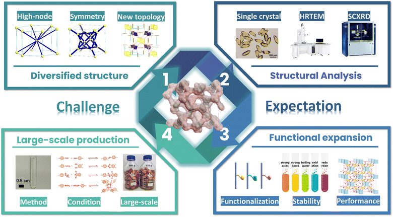
Exploring high-connectivity three-dimensional covalent organic frameworks: topologies, structures, and emerging applications
Fengqian
Chen
,
Haorui
Zheng
,
Yusran
Yusran
,
Hui
Li
*,
Shilun
Qiu
and
Qianrong
Fang
 *
*
State Key Laboratory of Inorganic Synthesis and Preparative Chemistry, Jilin University, Changchun 130012, P. R. China. E-mail: qrfang@jlu.edu.cn; HuiL@jlu.edu.cn
First published on 25th November 2024
Abstract
Covalent organic frameworks (COFs) represent a highly versatile class of crystalline porous materials, formed by the deliberate assembly of organic building units into ordered two-dimensional (2D) and three-dimensional (3D) structures. Their unique combination of topological precision and tunable micro- or mesoporous architectures offers unmatched flexibility in material design. By selecting specific building units, reactive sites, and functional groups, COFs can be engineered to achieve customized skeletal, porous, and interfacial properties, opening the door to materials with optimized performance for diverse applications. Among recent advances, high-connectivity 3D COFs have emerged as a particularly exciting development, with their intricate network structures enabling unprecedented levels of structural complexity, stability, and functionality. This review provides a comprehensive overview of the synthesis strategies, topological design principles, structural characterization techniques, and emerging applications of high-connectivity 3D COFs. We explore their potential across a broad range of cutting-edge applications, including gas adsorption and separation, macromolecule adsorption, dye removal, photocatalysis, electrocatalysis, lithium–sulfur batteries, and charge transport. By examining these key areas, we aim to deepen the understanding of the intricate relationship between structure and function, guiding the rational design of next-generation COF materials. The continued advancements in this field hold immense promise for revolutionizing sectors such as energy storage, catalysis, and molecular separation, making high-connectivity 3D COFs a cornerstone for future technological innovations.
1. Introduction
Covalent organic frameworks (COFs) are a class of crystalline porous materials composed of organic molecules connected by covalent bonds.1–6 These materials exhibit exceptional structural tunability, high surface area, and porosity, along with controllable physical and chemical properties. As a result, COFs have attracted significant attention in fields such as catalysis,7–9 gas adsorption and separation,10–13 sensing,14–16 energy storage,17–20 and many others.21–26 This concept of COFs was first proposed by Yaghi et al. in 2005.27 COFs share similarities with traditional inorganic crystalline materials, as they possess highly ordered structures, but are entirely constructed from organic molecules. This novel material bridges the gap between conventional polymers and inorganic materials, expanding the landscape of materials science.28,29The development of COFs has evolved through several stages, starting with the establishment of synthesis methods and structural characterization.30–32 As research progressed, the unique properties and potential applications of COFs became more apparent.33–35 In recent years, advances in synthesis techniques have led to the development of new COF structures with enhanced functionalities.36–38
High-connectivity COFs represent a special subset of COF materials, characterized by building units with more than four connections. These COFs often exhibit greater structural complexity and diversity. Overall, high-connectivity COFs possess several key features. Firstly, they are composed of building units with high-connectivity, enabling greater designability and a richer array of active sites. Secondly, they exhibit higher porosity and surface area, and can provide greater adsorption surface. Moreover, high-connectivity COFs display heightened robustness, and can function under a wide range of temperature and environmental conditions. Therefore, the development of high-connectivity COFs holds significant importance. On the one hand, novel synthesis strategies for high-connectivity COFs push the boundaries of COF research, advancing both their structure and properties. On the other hand, their enhanced structural and functional versatility makes them ideal candidates for complex catalytic processes, gas separation, and other advanced applications, broadening the scope of COF technology.
While numerous reviews have focused on two-dimensional (2D) and three-dimensional (3D) COFs, there is currently no comprehensive review specifically addressing high-connectivity 3D COFs. This review aims to fill that gap by first outlining the topological design principles of high-connectivity 3D COFs, including building units, construction strategies, and connectivity. We then discuss the development of high-connectivity 3D COF topologies, characterization techniques, and potential applications. Finally, we provide a summary and outlook for future research in this area.
2. Topological structure design principles
The field of synthesis and characterization of COF materials is advancing rapidly in chemical science, driven by their exceptional structures and significant potential in various applications.2,39–42 To fully comprehend these materials, it is crucial to delve into their topology types and symmetries. Firstly, it is essential to understand the concept of the topology and symmetry. In reticular chemistry, the topology is a mathematical model that describes the connectivity between atoms or units within molecular, crystal, or material structures. It can be represented by a set of nodes and edges. Topology provides information about the stability, structural properties, and crystal defects of molecules and crystals. Simultaneously, symmetry refers to the various operations that exist in molecular, crystal, or material structures, which keep them invariant or possess certain repetitive patterns under these operations. In crystallography, a space group represents the set of all symmetry operations in a crystal structure. Space group symmetry describes the repetition and symmetry in space of a crystal and plays a crucial role in the study of crystal stability, crystal growth, phase transitions, and other phenomena.43By designing suitable building units, selecting effective synthetic strategies, and promoting link formation, we can gain a comprehensive understanding of COFs’ topological types, network structures, and symmetries. This knowledge serves as a valuable resource for material design, catalytic reactions, and predicting material performance. It propels advancements in the COF field and lays the foundation for the development of highly specific and superior performance COFs. Therefore, approaching the synthesis and characterization of COFs from the perspectives of building unit design, synthetic strategy selection, and link formation allows for meaningful progress in this field. Below, we will introduce high-connectivity COFs from three perspectives: the design of building units, selection of building strategies, and formation of linkages.
2.1. Design of building units
COFs are designed based on principles of reticular chemistry, combined with the theory of topology. They are formed by connecting specific building units through reversible covalent bonds, resulting in crystalline and extended porous structures. In general, the topological information of vertices and edges and connectivity are well-defined for a given topology. For highly symmetric topological structures, researchers can determine the geometric shapes of building units based on detailed information from the Reticular Chemistry Structure Resource (RCSR) website on topological structures. This information can be used to rationally select building units for the synthesis of COFs.The design of the structure for 2D COFs is relatively straightforward. Since 2D structures commonly utilize π–π stacking in the z-axis direction, it is only necessary to consider the length of the selected building units in the x-y plane, as well as the formed angle and combination.29,44,45 For instance, combinations of C2, C3, C4, and C6 units can lead to the formation of 2D COFs with various topological structures such as hcb,46,47sql,48kgm,49hxl,50fxt,51,52kgd,53cpi,54bex,55htb,56mcm,57 and tju.58
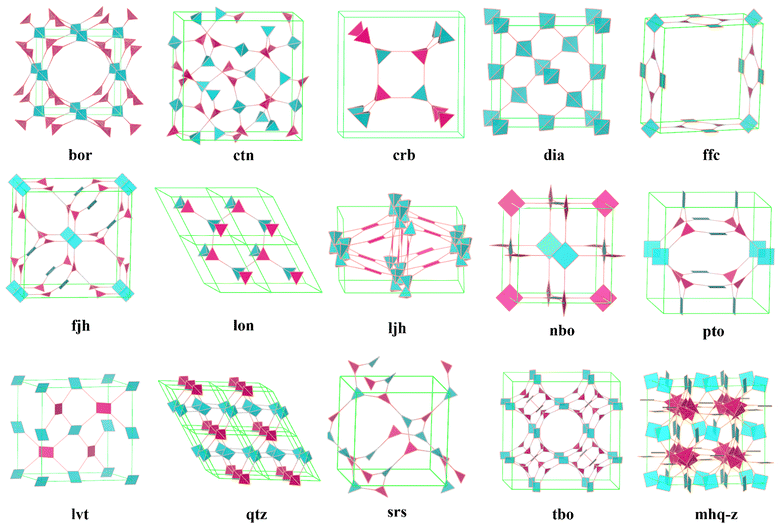
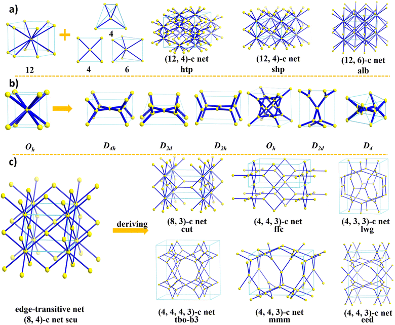
On the other hand, the design of 3D COF structures, especially high-connectivity 3D COFs, is significantly more complex compared to 2D COFs. As the dimensionality increases, we need to consider not only the lengths, angles, and connectivity of building units in three dimensions but also the phenomenon of interpenetration, which is unavoidable in some 3D COFs. This adds to the challenges in synthesizing and characterizing 3D COFs. It is important to highlight that the three-dimensional spatial arrangement endows 3D COFs with interconnected pore networks, an enhanced surface area, and additional active sites that are absent in their 2D counterparts. Consequently, advancing the development of 3D COFs is of considerable significance. However, the difficulties in forming extended 3D networks and determining the corresponding crystal structures have limited the number of reported 3D COFs. Currently, there are only over ten reported topologies composed of ≤4-connected building units (bor,30ctn,30crb,59dia,60,61ffc,40fjh,62lon,38ljh,63nbo,64pts,65lvt,66qtz,67srs,41tbo,68 and mhq-z69) (Fig. 1). In order to drive progress in the field of 3D COFs, particularly in creating more diverse structures, researchers are now focusing on expanding the diversity of COFs through innovative structural engineering. This includes exploring new topological structures, building units, and connection types. Here, we will discuss, from the perspective of building unit design, three aspects of how to expand the structural diversity of high-connectivity 3D COFs. This meticulous design approach can help us fully harness the advantages of 3D COFs and create structures with greater potential for applications.
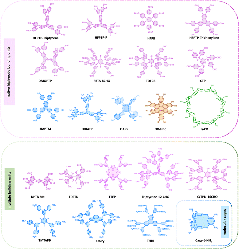
An intriguing approach to constructing high-connectivity 3D COFs is the design of diverse high-connectivity molecular cages. With inherent cavities and porosity, organic molecular cages, when utilized as building units to construct extended networks, not only combine the advantages of soluble cage molecules with the robustness and durability of polymer systems but also enhance the structural diversity of COFs.70,71 However, due to the challenges in structure design and control, there are currently only a few successful examples of organic cages used for constructing high-connectivity 3D COFs. One notable instance is Cage-6-NH2, a cage-like molecular connector with a triangular prism spatial structure, designed by Cooper et al. in 2020.72 Another approach is to utilize native high-connectivity building units for the synthesis of high-connectivity 3D COFs. This method involves synthesizing molecules that inherently possess multiple independent functional groups, such as polycyclic compounds and triptylene derivatives, as building units for COFs. As early as 2017, Wang et al. utilized g-cyclodextrin (γ-CD), a flexible macrocycle with numerous primary and secondary OH groups, as an 8-node building unit to construct a periodically extended 3D network. Subsequently, Fang et al. developed several triptylene derivative building units with triangular prism structures, such as 2,3,6,7,14,15-hexa(4-formylphenyl) triptylene (HFPTP-triptylene),73 2,3,6,7,14,15-hexa(3′-fluorine-4′-formylphenyl) triptylene (HFPTP-F),74 and 2,3,6,7,14,15-hexa(3′,5′-diisopropyl-4′-amino) triptylene (HDIATP).75 Additionally, by leveraging the steric hindrance effect, a compound featuring eight aldehyde sites, 2,3,5,6-tetrakis(([3,5-diformylphenyl]-5-yl)-9H-carbazol-9-yl)-1,4-benzenedicarbonitrile (TDFCB),76 was developed. In a similar vein, leveraging steric hindrance, Zhang and co-workers developed a new 8-node building unit known as (3,6-difluorobenzene-1,2,4,5-tetrayl)tetrakis(azanetriyl) octakis[1,1′-biphenyl]-4-carbaldehyde (FBTA-8CHO).77 Recently, 2,3,6,7,10,11,14,15,18,19,22,23-dodecahydroxycata-hexabenzocoronene (3D-HBC) was introduced, featuring 12 hydroxyl groups. During its condensation with boronic acid groups, each pair of adjacent hydroxyl groups engages in a selective reaction with a single boronic acid moiety, culminating in the formation of a 6-node inverted triangular prism.78 Then as planar units with D3d symmetry, hexa(4-formylphenyl)benzene (HFPB) and 2,3,6,7,10,11-hexakis(4-formylphenyl)triphenylene (HFPTP-triphenylene) can be assembled into specific topologies of 3D COFs.79,80 Liu and co-workers presented an 8-connected D2h building unit, 6,13-dimethoxy-2,3,9,10,18,19,24,25-octa(4′-formylphenyl)-pentiptycene (DMOPTP), based on pentiptycene. The DMOPTP features a unique 3D homoaromatic conjugated framework, which enhances the suitability of the synthesized 3D-scu-COFs for use in energy storage systems.81 Recently, Yu et al. incorporated polyhedral oligomeric silsesquioxanes (POSS) with amino-substituted inorganic siloxane cores, octa(4-aminophenyl)silsesquioxane (OAPS) into COF materials, characterized by a rare Oh symmetric configuration and appealing inorganic properties.82 Lan and co-workers reported a hexa(4-formylphenoxy)cyclotriphosphazene (CTP), a 6 connecting aldehyde-based building unit derived from a flexible cyclotriphosphazene unit, which can be induced to form a C3 anti-triangular prism configuration.83
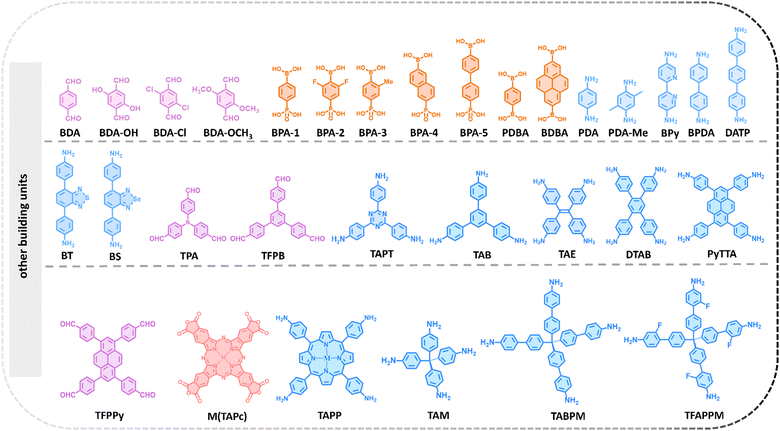
Finally, developing multiple building units is also a method to broaden the diversity of high-connectivity 3D COFs. Multiplying building units can be achieved through Suzuki coupling reactions to connect benzene boronic acid molecules, which inherently possess multiple functional groups, to substrate molecules with different shapes and multiple reactive bromine sites, leading to a proportional increase in the number of nodes. In 2022, Zheng and co-workers synthesized a novel D2h 8-node connector, 4′,5′-bis(3,5-diformylphenyl)-3′,6′-dimethyl-[1,1′:2′,1 -terphenyl]-3,3 ,5,5′′-tetracarbaldehyde (DPTBMe), through the Suzuki coupling reaction of 1,2,4,5-tetrabromo-3,6-dimethylbenzene and 5-(4,4,5,5-tetramethyl-1,3,2-dioxaborolan-2-yl) isophthalaldehyde. The eight aldehyde groups attached to the benzene ring radiate outward, projecting into distinct spatial coordinates.84 Subsequently, 8 connecting building units based on the same strategy were also reported, including 5,10,15,20-tetrayl(tetrakis(([1,1′:3′,1′′-terphenyl]-4,4′′-dicarbaldehyde)))-porphyrin (TTEP),85 1,3,6,8-tetrakis 3,5-bis[(4-amino)phenyl]phenyl pyrene (OAPy),86 and 3,3′,5,5′-tetra(3′′,5′′-diformylphenyl)-2,2′,6,6′-tetramethoxy-4,4′-dimethyl biphenyl (TDFTD).76 Notably, Wei and co-workers recently achieved the synthesis of 5′,5′′′′,5′′′′′′′,5′′′′′′′′,5′′′′′′′′′′′′′,5′′′′′′′′′′′′′′′′-(9,10-dihydro-1,2-benzenoanthracene-2,3,6,7,14,15-hexayl) hexakis ([1,1′:3′,1′′-terphenyl]-4,4′′-dicarbaldehyde), (triptycene-12-CHO)87 through a Suzuki coupling reaction between 2,3,6,7,14,15-hexabromo triptycene and 5′-(4,4,5,5-tetramethyl-1,3,2-dioxaborolane-2-yl)[1,1′:3′,1′′-terphenyl]-4,4′′ dicarbaldehyde. This achievement extends the building units available for COF construction to a 12-node configuration. Concurrently, Jiang and co-workers also successfully synthesized a 12-node structure, 5,5′,5′′,5′′′,5′′′′,5′′′′′-(triphenylene-2,3,6,7,10,11hexayl) hexa(isophthalohydrazide) (THHI-NH2),88 further enriching the toolkit for COF construction. By using 2,3,5,6-tetrafluoroterephthalonitrile as a foundation and expanding its functional groups step by step, Lan and co-workers recently succeeded in creating 2,3,5,6-tetrakis(3,6-bis(3,5-diformylphenyl)-9H-carbazol-9-yl)terephthalonitrile (CzTPN-16CHO), a compound featuring 16 nodes.89 This development enhances the node count of building units for COF synthesis to 16. These high-valency building units have significantly expanded the available topological structures of 3D COFs. It warrants attention that this method has the potential to be an excellent strategy for constructing complex high-connectivity 3D COFs. In theory, a substrate containing multiple bromine reaction sites can be used to synthesize multi-node building units with various reaction types. This method offers countless possibilities for the design of COF building units. Representative building units for the construction of high-connectivity 3D COFs is provided in Fig. 2 and 3.
2.2. Selection of the synthetic strategy
In addition to the design of building units, an important step in the topology design of high-connectivity 3D COFs is the selection of building strategies. When designing high-connectivity 3D COFs, several aspects need to be considered: First, suitable high-connectivity building units need to be selected, which possess multiple functional groups to provide the desired reaction sites. Second, appropriate additional building units should be chosen to connect with the high-connectivity building units, depending on the desired topology. These connections should be directional and form stable bonds. Furthermore, the hybridization angles and distances between building units need to be considered to achieve the desired 3D COF topology. The employed building strategies can be roughly categorized into the following three types:Firstly, the synthetic strategy based on high-connectivity stereoisomeric building units: this strategy involves using stereoisomeric building units with a high number of connections as the core, and combining them with various building units with different linkages to achieve the synthesis of high-connectivity 3D COFs. The selected stereoisomeric building units in this strategy provide multiple connection sites in different directions, enabling the formation of diverse and flexible 3D COF structures. This strategy is the most widely applied design strategy currently. However, stereoisomeric building units with a high number of connections have complex structures and are challenging to synthesize. Additionally, the connectivity and directionality of the stereoisomeric building units need to be considered in the design. Precise synthesis and assembly techniques need to be mastered, which severely limits the expansion of high-connectivity 3D COFs.
Secondly, the synthetic strategy based on high-connectivity planar building units: this strategy utilizes planar building units with different functional groups to achieve the construction of 3D topology. Compared to stereo-building units, planar building units have better scalability and controllability, but they require higher design requirements for topology and have fewer options for building units. Currently, most reports focus on the [4+3] connection topology construction,40,62,68,90 with only the she topology being reported for high-connectivity 3D COFs.79
Thirdly, the synthetic strategy based on special reaction: this strategy employs specific reaction types to construct high-connectivity 3D COFs. Special reaction types enable specific chemical reactions and functional properties, providing more options for constructing high-connectivity 3D COFs. However, the selection and design of special reaction types require extensive expertise and technical knowledge, potentially posing a higher barrier for researchers. Currently, only the Yaghi research group has reported an in situ synthesis method for the synthesis of porous octadecane structures through self-condensation of 1,4-borophenyl phosphonic acid ligands.91
2.3. Determination of linkages
The linkages, a crucial component, control the properties of 3D COFs and connect building units to form the desired framework. Therefore, it is a feasible strategy to increase the diversity of 3D COFs by forming different linkages through the selection of appropriate building units and reaction conditions. It is worth mentioning that COFs form crystalline structures through persistent reversible reactions via covalent bonds, so the required linkages are often rigid and dynamic.92 The reversibility of linkages directly influences the difficulty of COF formation and the degree of crystallinity. In general, weaker covalent interactions are more easily reversible, thus favoring the formation of highly crystalline COFs, while overly strong covalent interactions may hinder the formation of highly crystalline frameworks. Imine bonds, with their moderate reversibility and stability, can be utilized to construct highly crystalline COFs exhibiting satisfactory stability in a wide range of conditions.13,93–95 Currently, the majority of reported high-connectivity 3D COFs are linked by imine bonds, with only a small number of other bond types being explored. Therefore, introducing linkages of COFs (such as triazine,92 azine,16 hydrazone,96 urea,97etc.) remains a critical research direction for expanding high-connectivity 3D COFs.3. Development process of high-connectivity 3D COFs
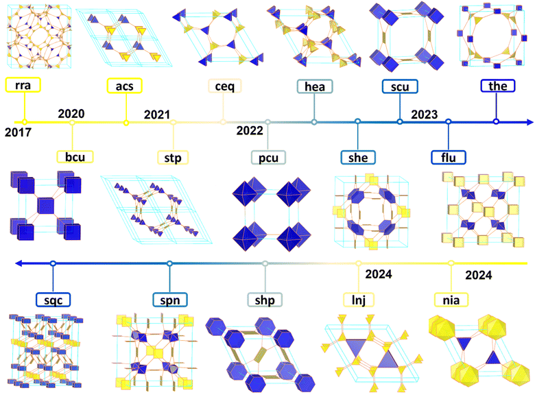
Due to the challenge of synthesizing building units with a valence higher than four, efforts have been made to increase the valence and dimensionality of COF building units (Fig. 4). These efforts aim to overcome the limitations caused by the hybridization of organic building units with different plane geometries (sp1, sp2, and sp3). In 2020, Yaghi and co-worker developed an in situ formation method to synthesize porous bcu structures.91 This method involved the self-condensation of 1,4-borophenyl phosphonic acid ligands with equal electrons from boron and phosphorus, both of which served as carbon group elements. This breakthrough drove COF chemistry into new valence states. In the same year, Cooper and co-workers achieved a breakthrough by synthesizing the first cage-structured 3D COF (3D-CageCOF-1), utilizing an organic cage molecule, Cage-6-NH2. Subsequently, through structural analysis and comparison, it was found that the material has a 2-fold interpenetrated acs topology.72 Afterwards, Fang et al. synthesized a 3D COF (JUC-569) featuring a non-interpenetrated acs topology using a triangular prism (6-connected) node (HFPTP-triptycene) with another triangular prism node (HDIATP).75 Additionally, the research group combined 6-connected (D3h) triptycene building units with planar quadrilateral (PyTTA), planar triangular (TAPT), 3D tetrahedral (TFAPPM) and planar hexagonal (HAPTM) building units to synthesize 3D COFs with non-interpenetrated stp,73ceq,75hea,74 and nia98 topologies. In 2022, Zhang et al. synthesized a 3D COF with bcu topology connected by imine bonds using a bottom-up synthetic strategy with 8-connected building units (DPTB-Me).84 Subsequently, Peng et al. introduced 8-connected building units (OAPy) with D4h symmetry to synthesize a 3D COF with 2-fold interpenetrated bcu topology, following the same design concept.86 Subsequently, Zhang and colleagues successfully synthesized two highly crystalline 3D COFs by utilizing an [8+4] synthetic strategy, which involved the combination of octa-aldehyde building units (DPTB-Me) with porphyrin-based tetra-amine building units. The COF structures were successfully identified as having a non-interpenetrated scu net through the use of continuous rotation electron diffraction (cRED) techniques, combined with structural simulations.99 One year later, Negishi and co-worker, utilizing the same octa-aldehyde building units, achieved a novel 3D COF with the topology through an [8+3] synthetic approach.100 Jiang and co-workers also achieved the synthesis of two new 3D COFs with 2-fold interpenetrated scu topology, by rationally designing a 4-connected square-planar building unit (TAPPy or TAPP) and an 8-connected pentiptycene-based D2h building unit (DMOPTP).81 Notably, the topological structure of tty can also be achieved through the [8+4] reticular strategy. Zhang et al. fabricated an octa-aldehyde difluorobenzene monomer, FBTA-8CHO, as an 8-connected cubic node, and utilized TAppy as a rectangular connector to construct COF-NUST-16, which exhibited characteristic tty topology.77 Subsequently, the research team synthesized two distinct COFs with scu and flu topologies, named NUST-18 and NUST-19, respectively, by condensing an octahedral aldehyde building unit based on porphyrin (TTEP) with planar (DTAB) and stereo (TAM) 4-node amine building units. This demonstrated the capability of achieving various COF topological structures by judicious selection and arrangement of different building units.101 As research progressed, the development of building units with higher nodal degrees became a focus. In 2024, Wei and co-worker, building upon a triptycene framework, designed and synthesized a novel 12-aldehyde nodal building unit (triptycene-12-CHO), successfully obtaining a 3D COF with an innovative lnj topology known as 3D-lnj-COF. This advancement not only highlighted the mastery over the synthesis of highly complex COF structures but also expanded the directions for future COF design and applications.87 Meanwhile, Jiang and co-workers synthesized another 12-node building unit based on triphenylene. By condensing this 12-node building unit (THHI) with a planar 4-node anhydride building unit (M(TAPc)) using a [12+4] synthetic approach, they crafted MPc-THHI COFs (M = H2, Ni) with shp topology. This achievement added to the structural diversity of high-dimensional COFs and provided valuable insights for exploring the structures and properties of novel high-connectivity COFs.88 Recently, Jiang et al. utilized OAPS as an 8-connected amino building unit and, by altering the type of metalloporphyrin under identical synthesis conditions, they combined OAPS with the 4-connected tetrakis[4-formylphenyl]-porphyrin (MTFPP, M = Co, Zn, Ni, 2H). This approach led to the formation of two types of COFs featuring scu and sqc networks.102 Subsequently, Lan et al. employed a [16+2] construction strategy, condensing the 16-node CzTPN-16CHO with linear building units of BD/Bpy, which similarly resulted in the sqc network structures of CZBBD COFs and CZBpy COFs.89In addition to the topological structures mentioned above, several different topologies of 3D COF with special building units or construction methods have been developed. In 2017, Wang et al. reported a novel CD COF based on the rra topology. This COF is formed through the covalent bonding of spiroborate and Y-cyclodextrin (Y-CD) molecules.34 In 2022, Huang and co-worker used HFPB as the D3d building unit and 5,10,15,20-tetra(4-aminophenyl) porphyrin (TAPP) as the D4h building unit to synthesize a sequence of 3D COFs. In this architecture, each D3d building unit is linked to six D4h building units, resulting in the formation of a non-interpenetrated she network.79 Mateo-Alonso and co-workers successfully synthesized a distorted polycyclic aromatic hydrocarbon monomer, 3D-HBC, as a 3D 6-node building unit. Through the condensation process between 3D-HBC and linear diboronic acid, a sophisticated 3D COF was generated, ultimately constructing a 6-fold interpenetrated pcu network.78 Recently, Lan et al. ingeniously induced the formation of a C3 anti-triangular prism 3D building block by utilizing a planar building block derived from the flexible cyclotriphosphazene unit, CTP. This was then condensed with planar tri-node building units TAPA or TAB to construct two 3D COFs with spn topology, named TAA/TAB-CTP-COF.83
4. Precise structural analysis of 3D COFs
In recent years, with the rapid advancement of reticular chemistry, high-connectivity 3D COFs have made significant progress in structural complexity and diversity, giving rise to increasingly intricate structural forms. As porous materials with wide-ranging application prospects, the practical uses of high-connectivity 3D COFs depend on their physical and chemical properties, which are significantly influenced by their crystal structures and atomic arrangements. Therefore, accurately determining the structures of high-connectivity 3D COFs is of utmost importance. However, the methods currently available for analyzing high-connectivity 3D COFs remain relatively limited. In this chapter, we will draw on several typical cases of 3D COF analysis in the hope of providing insights and advancing research in the field of high-connectivity 3D COFs.During the initial stages of 3D COF structure development, researchers primarily determine the structure through the following steps: firstly, based on the node number and geometric configuration of building units, they search for similar connection methods and topological structures in the Reticular Chemistry Structure Resource (RCSR) database. Subsequently, Materials Studio software is used to construct the crystal structure and perform crystal simulations according to the building units. Next, experimental powder X-ray diffraction (PXRD) data is compared with simulated XRD patterns to ascertain the structure of the synthesized material, thereby obtaining key information such as unit cell parameters, atomic positions, and topological structure to reveal the 3D structural information of the material.
Furthermore, advanced computational methods and simulation techniques such as density functional theory (DFT) and molecular dynamics simulations allow researchers to conduct in-depth investigations into the structure of 3D COFs. By optimizing molecular structures and calculating self-consistent electronic structures, geometric and electronic structure parameters of 3D COFs can be obtained. The combination of these experimental and theoretical methods provides powerful means for accurately describing the structure of 3D COFs. However, the unambiguous determination of 3D COF structures is challenging, considering the complexity of 3D COFs, as the overlap and broadening of peaks in PXRD often lead to difficulties in peak assignment and peak intensity calculation. Determining structures based on PXRD becomes even more challenging when crystals have large unit cell dimensions or samples contain multiple phases.
4.1. 3D electron diffraction (3D ED)
For COFs with sufficiently good crystallinity but small crystal size, the challenge of resolving the structure of such materials can be addressed using 3D ED technology.103 Over the past two decades, the development of 3D ED technology has overcome the obstacles in analysing nano- and submicron-scale crystal structures and has been widely applied for structural determination of nanoscale crystals. It is generally believed that crystals only a few hundred nanometers in size can be effectively analyzed. While even smaller crystals can still provide high-quality data, an ideal crystal size is between 200–500 nanometers to optimize the resolution and quality of diffraction patterns. This size range ensures precise crystal orientation and data collection while minimizing potential radiation damage during analysis. This technology has been successfully employed in determining the crystal structures of 3D COFs, providing crucial insights into the relationship between their structure and properties.In 2013, Yaghi and co-workers first reported single crystal 3D COFs, including COF-320. The structure of COF-320 was successfully analysed by collecting 3D ED data with a resolution of 1.5 Å.104 The data were collected using 3D ED at both 298 K and 89 K. The cooling of the sample is very important for reducing the damage of the beam to the material, and it also has a significant impact on the quality of the data. Refining the 3D ED data revealed that COF-320 possesses a 3D extended framework structure with a 9-fold interpenetrated dia net along the c-axis direction. Additionally, the overall structure exhibits a one-dimensional (1D) rectangular channel measuring 13.5 Å × 6.2 Å.
In 2019, Wang et al. determined the structures of a series of 3D COFs (3D-TPB-COF-H, -Me, and -F) through cRED analysis.105 The data were captured at 99 K with an approximate exposure time of 270 seconds per dataset. The resolutions reached 1.0 Å for 3D-TPB-COF-H and 3D-TPB-COF-F, and 0.9 Å for 3D-TPB-COF-Me. Non-hydrogen atoms, including -Me and -F groups, were accurately mapped using direct or charge-flipping methods, marking a breakthrough in directly pinpointing non-hydrogen atoms in a polycrystalline COF sample. All three COFs exhibit a 5-fold interpenetrated pts topology.
Recently, they grew 3D COF single crystals with large-sizes under solvothermal conditions without the addition of competitive reagents. The crystal structure of 3D-TMTAPB-COF was determined through the application of cRED technology.106 The data were collected at 99 K, followed by the reconstruction of 3D reciprocal lattices utilizing REDp data processing software. Based on the reconstructed cell parameters, the cell parameters were determined to be a = b = 16.15 Å, c = 36.93 Å, α = β = 90°, and γ = 120°. By merging six datasets, the position of the central node (TMTAPB) was successfully determined in the P6cc space group using SHELXT software (Fig. 5). Furthermore, the integrated structural model containing all non-hydrogen atom positions was supplemented using Materials Studio 2019 software.
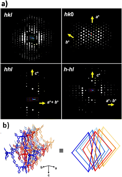 | ||
| Fig. 5 (a) The 3D reciprocal lattice of 3D-TMTAPB-COF. (b) Structural representation of 3D-TMTAPB-COF (reproduced from ref. 106 with permission from American Chemical Society, Copyright 2023). | ||
Later, Bu et al. synthesized two mesoporous 3D COFs using aniline as a modulator, which exhibited a non-interpenetrated stp net.107 Based on the collected 3D ED data, the reconstructed 3D reciprocal lattice indicated that COF-HFPTP-TAE has a hexagonal P lattice with lattice parameters of a = b = 48.95Å, c = 16.94Å, α = β = 90°, and γ = 120°. Subsequently, they refined the lattice parameters of COF-HFPTP-TAE through Le-Bail fitting, determining the unit cell to be a = b = 47.44Å, c = 15.50Å, with α = β = 90°, and γ = 120°, thus elucidating the crystal structure (Fig. 6)
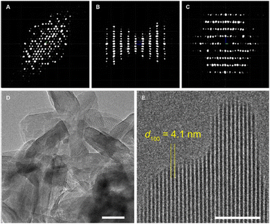 | ||
| Fig. 6 TEM characterization of COF HFPTP-TAE, including projection views of 3D ED data along c*, b*, and a*, respectively (reproduced from ref. 107 with permission from American Chemical Society, Copyright 2023). | ||
4.2. Single crystal X-ray diffraction (SCXRD)
SCXRD analysis is currently the primary method for determining atomic-level crystal structures, but it requires sufficiently large crystals. However, the majority of COFs obtained at present consist of nano- or submicron-scale crystals, rendering this technique unsuitable for resolving crystal structures.The synthesis of single-crystal 3D COFs has long been regarded as a pivotal breakthrough. In 2018, Wang and co-workers successfully prepared a series of single-crystal 3D imine-linked COFs (COF-300, LZU-79, COF-303, and LZU-111) through modulation with aniline.38 SCXRD analysis enabled precise determination of crystal details such as atomic positions, unit cell parameters for specific space groups, and geometric parameters (such as lengths and angles of the bonds). The study demonstrated that aniline, due to its similar reactivity with many COF building units, acts as a nucleation inhibitor and modulator. Its presence improved the reversibility of imine bond formation and facilitated error correction, resulting in higher crystallinity. This presents significant potential for exploring the structure–property relationships of 3D COFs and the absorption of guest molecules, thereby providing a pathway for in-depth investigation of the mechanisms involved in 3D COF research.
In 2020, Wang et al. reported a single crystal COF, named LZU-306, through an aniline modulation strategy.108 SCXRD analysis confirmed that LZU-306 possesses a non-interpenetrated pts network and an open structure entirely formed through covalent assembly. In the same year, Yaghi and co-workers synthesized a series of porous polyhedral carbon frameworks (BP-COF-1 to 5) using isoelectronic combinations with boron and phosphorus as the carbon-based elements.91 Despite the inadequate crystal quality of BP-COF-1 to 5, the authors successfully obtained a large single crystal of BP-COF-6 composed of rod-shaped units by modifying the reaction conditions. The crystal structure of BP-COF-6 was elucidated through SCXRD analysis, which unveiled a unique arrangement where infinite 1D B–O–P rods are substituted by alternating tetrahedral units of boron and phosphorus.
4.3. High resolution transmission electron microscopy (HRTEM)
In most cases, the crystal quality of high-connectivity 3D COFs is insufficient to support their analysis using 3D ED and SCXRD. Consequently, the majority of researchers opt for transmission electron microscopy (TEM). Electron microscopy can determine the periodic and local structures of COFs through real-space imaging. However, the extreme fragility of COF structures under electron beam irradiation precludes direct application for structural analysis. Low-dose HRTEM allows for structural determination of electron beam-sensitive materials, enabling the determination of the periodic and local structures of COFs. Currently, this method serves as a widely utilized auxiliary tool for the structural analysis of 3D COFs. For high-connectivity 3D COFs, their structures are relatively complex, making their precise determination particularly challenging, especially in the case of interpenetrating structures. In fact, identifying the commonly encountered interpenetrating structures in many COF and MOF systems is not straightforward. The entanglement of these networks does not create any added structural order compared to a single network, rendering them difficult to discern using conventional difference-based characterization methods. However, electron microscopy presents a compelling alternative, offering a direct view of these entangled networks in real space. By capturing their structural projections with precision, it reveals the intricate diversity of these systems, providing a clearer and deeper understanding of the hidden complexities within their entanglements.In 2021, Zhao et al. reported two unique 3D COFs, Trip-COF 1 and Trip-COF 2, with stp topology.109 By tuning the monomer size and adjusting the reaction conditions to induce controlled interpenetration, TEM imaging has confirmed the exceptional crystallinity of the resulting Trip COFs. In Trip COF 1, the hexagonal pores are distinctly visible, accompanied by some one-dimensional channels. However, in Trip COF 2, the interpenetration of networks renders the hexagonal pores nearly indiscernible, replaced by the predominant appearance of numerous one-dimensional channels. This striking shift in structure highlights the profound influence of interpenetration on the material's microarchitecture, showcasing its intricate complexity. In 2022, Peng et al. clearly demonstrated the double entanglement and rhombus-shaped dark contrast in the HRTEM images of ZJUT-3 using contrast transfer function (CTF) calibration.86 As shown in Fig. 7a, the double interpenetrated network of ZJUT-3 can be clearly identified in different projections.
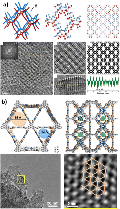 | ||
| Fig. 7 (a) HRTEM imaging and structural model of ZJUT-3 (reproduced from ref. 86 with permission from Wiley-VCH, Copyright 2020). (b) HRTEM images and structural model for H2Pc-THHI-COF (reproduced from ref. 88 with permission from Wiley-VCH, Copyright 2024). | ||
Recently, Jiang and co-workers used HRTEM to capture images of MPcTHHI-COFs (M = H2, Ni), revealing the distinct long-range ordered structures of these covalent organic frameworks.88 In particular, the denoised HRTEM images showcased triangular pores with significantly enhanced contrast, closely associated with the open shp network channels organized along the vertical direction (c-axis) of the material (Fig. 7b). The observed structural features are consistent with data obtained from PXRD analysis and theoretical simulations, indicating a concordance between experimental observations and theoretical predictions.
Overall, HRTEM technology provides a clear visualization of the microscopic structure of materials and is of critical importance for understanding the visualization of COF structures, as well as for knowledge regarding the relationship between structure and function.
5. Application of high-connectivity 3D COFs
3D COFs constructed from high-connectivity building units not only possess rich pore structures, excellent tunability, and remarkable stability but also often exhibit more complex structures and abundant active sites. These features provide great potential for their wide-ranging applications in various fields, such as gas adsorption and separation, catalysis, energy storage, and optoelectronic devices. We have compiled a comprehensive summary of the adsorption capacities of high-connectivity 3D COFs for H2, CH4, and CO2, which is meticulously presented in Table 1.| Sample | Topology | Synthetic strategy | S BET/m2 g−1 | Pore size distribution/Å | CO2 uptake (273 K/298 K)/cm3 g−1 | CH4 uptake (273 K/298 K)/cm3 g−1 | H2 uptake (77 K/87 K)/cm3 g−1 | Ref. |
|---|---|---|---|---|---|---|---|---|
| 3D-OC-COF-H | acs | 6+2 | 1143 | 10.5/11.4 | 54.5/33.8 | 15/12 | —/— | 110 |
| 3D-OC-COF-OH | acs | 6+2 | 923 | 6.5 | 89.2/51.4 | 15/12 | —/— | 110 |
| 3D-OC-COF-Cl | acs | 6+2 | 660 | 5.3 | 36.8/19.5 | 15/12 | —/— | 110 |
| 3D-CageCOF-1 | acs | 6+2 | 1040 | 8.8/5.6 | 103.9/54.5 | —/— | —/— | 72 |
| 3D-ceq-COF | ceq | 6+3 | 1149 | 10/16 | 91.3/46 | 27/22 | 178/131 | 111 |
| JUC-568 | ceq | 6+3 | 1433 | 19.2 | 98/81 | 48/32 | 274/— | 75 |
| JUC-569 | acs | 6+6 | 1254 | 18.7 | 47/31 | 19/11 | 167/— | 75 |
| 3D-hea-COF | hea | 6+4 | 1804 | 9/16 | —/— | —/— | 193/131 | 111 |
| JUC-596 | hea | 6+4 | 2629 | 16.2/26.4 | 84/53 | 31/14 | 305/224 | 74 |
| JUC-597 | hea | 6+4 | 1857 | 15.8/25.9 | 70/31 | 25/8 | 148/100 | 74 |
| JUC-640-H | stp | 6+4 | 2204 | 46.5 | 52.2/31.9 | —/— | —/— | 112 |
| JUC-640-Co | stp | 6+4 | 2204 | 46 | 65.8/41.2 | —/— | —/— | 112 |
| JUC-640-Ni | stp | 6+4 | 2204 | 46 | 57.43/37.83 | —/— | —/— | 112 |
| BP-COF-1 | bcu | — | 519 | 6 | —/— | —/— | 130/— | 91 |
| ZJUT-2 | bcu | 8+2 | 744 | 10/18 | —/20.7 | —/6 | —/— | 86 |
| ZJUT-3 | bcu | 8+2 | 837 | 12/16 | —/16.1 | —/3.5 | —/— | 86 |
| JUC-588 | bcu | 8+2 | 2728 | 17 | 67/— | 16/— | —/— | 76 |
| JUC-589 | bcu | 8+2 | 2482 | 21/23 | 40/— | 12/— | —/— | 76 |
| NUST-5 | bcu | 8+2 | 680 | 10/15 | 25.5/16.3 | —/— | —/— | 85 |
| 3D-scu-COF-1 | scu | 8+4 | 2340 | 12/16/19/29 | 108/— | 30/— | —/— | 81 |
| 3D-scu-COF-2 | scu | 8+4 | 1602 | 11/17/21/30 | 115/— | 17/— | —/— | 81 |
5.1. Gas adsorption
At the inception of COF development, Yaghi and co-workers computationally simulated the H2 adsorption capacity of a series of COFs using grand canonical Monte Carlo (GCMC) calculations. They inferred that 3D COFs have H2 storage capacities 2.5–3 times higher than 2D materials.113 Subsequently, they achieved the successful synthesis of 3D COFs with impressive BET surface areas (3620 m2 g−1 for COF-102 and 3530 m2 g−1 for COF-103) and substantial pore volumes (1.55 cm3 g−1 for COF-102 and 1.54 cm3 g−1 for COF-103). Upon evaluating their H2 adsorption behaviour and capacity, COF-102 and COF-103 exhibited outstanding performance, with H2 adsorption capacities of 72.4 mg g−1 and 70.5 mg g−1, respectively, at 77 K and 35 bar. These values far surpassed those of 2D COFs, which did not exceed 39.2 mg g−1 under the same conditions, and were comparable to the best-performing MOFs and other porous materials.114
In recent years, the field of hydrogen storage has witnessed remarkable advancements through the exploration of novel 3D COF topologies, especially those incorporating triptycene motifs. Triptycene is notable for its unique triangular structure with 120° angles, D3h space group symmetry, rigid Y-shaped framework, and three open interior cavities. These features prevent π–π stacking, providing ample void space for optimizing framework pores and expanding spatial arrangements, making triptycene an ideal multi-node building unit for synthesizing 3D COFs.
In 2021, Fang and co-workers successfully synthesized JUC-568 and JUC-569, two non-interpenetrated COFs with novel ceq or acs topologies. These structures were ingeniously constructed by integrating a 6-connected triangular prism node derived from triptycene with either a 3-connected planar triangular node or another triangular prism node.75 Both COFs demonstrated permanent porosity and remarkable gas adsorption capabilities. JUC-568, in particular, demonstrated a high H2 adsorption capacity of up to 274 cm3 g−1 (2.45 wt%) at 77 K and 1 bar, while JUC-569, with acs topology (Fig. 8a), showed a H2 adsorption capability of 167 cm3 g−1 under unchanged conditions (Fig. 8b). Around the same time, He and co-workers synthesized a 3D-ceq-COF using triptycene derivatives HFPTP and TAPT, and thoroughly investigated the hydrogen storage capabilities of this framework.111 Their study revealed that 3D-ceq-COF displayed H2 uptake capacities of 178.49 cm3 g−1 and 131.27 cm3 g−1 at 77 K and 87 K (1 bar), with a Qst value of 8.83 kJ mol−1.
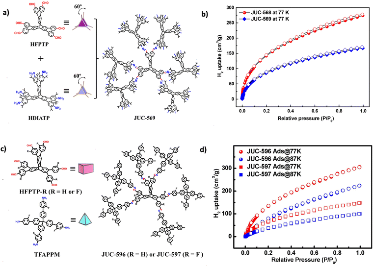 | ||
| Fig. 8 (a) Strategy for constructing JUC-569 with an acs net. (b) H2 uptakes for JUC-568 and JUC-569 measured at 77 K (reproduced from ref. 75 with permission from American Chemical Society, Copyright 2021). (c) Strategy for constructing JUC-596 and JUC-597 with a hea net. (d) H2 uptakes for JUC-596 and JUC-597 measured at different temperatures (reproduced from ref. 74 with permission from Wiley-VCH, Copyright 2022). | ||
Furthermore, both He et al. and Fang et al. extended the triptycene-based COFs and almost simultaneously reported the construction of 3D COFs with the hea network (Fig. 8c). He et al. synthesized a 3D-hea-COF with a hea-c network by condensing tetrahedral TABPM with Td symmetry and HFPTP with D3h symmetry.115 The material exhibited H2 adsorption capacities of 193.48 cm3 g−1 (1.73 wt%) at 77 K and 1 bar, and 131.03 cm3 g−1 (1.17 wt%) at 87 K and 1 bar, accompanied by a high BET surface area of 1804.0 m2 g−1.
In Fang et al.'s work, they introduced fluorine-substituted trigonal prismatic (HFPTP-F) and tetrahedral (TFAPPM) building units to construct two different 3D triptycene-based COFs, JUC-596 and JUC-597.74 Compared to the non-fluorinated 3D-hea-COF, these fluorinated COFs exhibited higher BET surface areas (2629 m2 g−1 for JUC-596 and 1857 m2 g−1 for JUC-597). Notably, JUC-596 demonstrated the highest reported H2 adsorption capacity among porous organic materials, reaching 305 cm3 g−1 (2.72 wt%) (Fig. 8d). The excellent H2 storage capabilities of these COFs were attributed to specific adsorption sites and the presence of fluorine atoms, as demonstrated by theoretical studies using DFT and GCMC simulations.
Recently, Fang and co-workers reported two new 3D COFs, JUC-588 and JUC-589, based on two different-sized cubic building units, TDFTD and TDFCB.76 These COFs featured a bcu network structure with micro- and mesopores. Both JUC-588 and JUC-589 exhibited high BET surface areas (2728 m2 g−1 for JUC-588 and 2482 m2 g−1 for JUC-589) and demonstrated significant H2 adsorption capacities. At 77 K and 1 bar, JUC-588 showed a H2 adsorption of 245 cm3 g−1 (2.19 wt%), while JUC-589 exhibited a H2 adsorption of 211 cm3 g−1 (1.89 wt%).
In 2020, Cooper and co-workers synthesized a high-connectivity COF based on organic cages, 3D-CageCOF-1, with a 2-fold interpenetrated acs network (Fig. 9a).72 Due to the relatively small pore size and highly decorated pore channels with oxygen and nitrogen atoms, 3D-CageCOF-1 exhibited excellent performance in water collection and CO2 absorption. The maximum CO2 uptake of 3D-CageCOF-1 at 273 K and 1 bar reached 204 mg g−1, and at 298 K and 1 bar, it reached 107 mg g−1 (Fig. 9b). Subsequently, Yuan and co-workers constructed an expanded structure (3D-OC-COF-H) and two distinct contracted variants (3D-OC-COF-OH and -Cl) based on the flexible 6-node building unit 6NH2-OC·4HCl.110 Their study delved into the application of these 3D OC COFs for CO2 adsorption. Notably, 3D-OC-COF-OH exhibited a significantly higher CO2 capacity (89.2 cm3 g−1 at 273 K, 51.5 cm3 g−1 at 298 K) compared to 3D-OC-COF-H (54.5 cm3 g−1 at 273 K, 33.8 cm3 g−1 at 298 K) and 3D-OC-COF-Cl (36.8 cm3 g−1 at 273 K, 19.5 cm3 g−1 at 298 K).
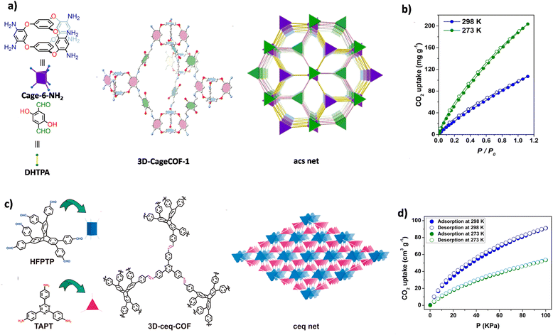 | ||
| Fig. 9 (a) Strategy for constructing 3D-CageCOF-1 with a 2-fold interpenetrated acs net. (b) CO2 adsorption–desorption isotherms of 3D-CageCOF-1 at different temperatures (reproduced from ref. 72 under the terms of the Creative Commons Attribution 4.0 International License. Copyright 2020, American Chemical Society). (c) Strategy for constructing 3D-CageCOF-1 with a 2-fold interpenetrated ceq net. (d) CO2 adsorption–desorption isotherms of 3D-ceq-COF at different temperatures (reproduced from ref. 111 with permission from American Chemical Society, Copyright 2021). | ||
Based on hexagonal building units, the 3D COFs designed by Fang and He et al., which are based on triptycene building units, exhibit excellent CO2 adsorption performance in addition to their remarkable H2 adsorption capabilities. JUC-568, JUC-569, JUC-596, and JUC-597 exhibited H2 uptake of 98 cm3 g−1, 47 cm3 g−1, 84 cm3 g−1, and 70 cm3 g−1, respectively, at 273 K and 1 bar.74,76 The corresponding 3D-ceq-COF (Fig. 9c) and 3D-hea-COF exhibited CO2 adsorption capacities similar to JUC-568 and JUC-596 (91.27 cm3 g−1 (Fig. 9d) and 80 cm3 g−1, at 273 K and 1 bar).111,115
Initial exploration has also been conducted on the CO2 adsorption capacity of 3D COFs based on 8-node building units. In 2022, Fang and co-workers synthesized JUC-588 and JUC-589, utilizing 8-node building units TDFTD and TDFCB. These frameworks exhibited CO2 uptake capacities of 67 cm3 g−1 and 40 cm3 g−1, respectively, under conditions of 1 bar and 273 K.76 In the same year, Zhang et al. synthesized NUST-5 and NUST-6 based on the TTEP building unit, and conducted CO2 adsorption tests at 195 K, 273 K, and 298 K.85 The study revealed that the CO2 adsorption capacities of NUST-5 and NUST-6 at 298 K were lower than those at 273 K (both at 1 atm). At 195 K, a remarkable surge in adsorption was observed, with the CO2 adsorption capabilities of NUST-5 and NUST-6 soaring to 113.53 cm3 g−1 and 119.21 cm3 g−1, respectively.
![[thin space (1/6-em)]](https://www.rsc.org/images/entities/char_2009.gif) 840 COFs, and studied their CH4 adsorption performance.6 Through analysis, they found that the topological structure and connectivity influence the CH4 adsorption performance of 3D COFs. Some network structures, such as qzd, pth, and pts, were found to exhibit better CH4 adsorption performance in C–N bond binding structures, while other network structures, such as ukk, uon, and dia, performed better in C–C bond binding structures.
840 COFs, and studied their CH4 adsorption performance.6 Through analysis, they found that the topological structure and connectivity influence the CH4 adsorption performance of 3D COFs. Some network structures, such as qzd, pth, and pts, were found to exhibit better CH4 adsorption performance in C–N bond binding structures, while other network structures, such as ukk, uon, and dia, performed better in C–C bond binding structures.
In recent studies on high-connectivity 3D COFs, most explored their CH4 adsorption performance under atmospheric pressure. For example, JUC-568 with the ceq net demonstrated CH4 adsorption capacities of 48 cm3 g−1 at 273 K and 32 cm3 g−1 at 298 K.75 JUC-596 and JUC-597 with the hea net exhibited relatively lower CH4 uptake, with capacities of 31 cm3 g−1 and 14 cm3 g−1 at 273 K, and 25 cm3 g−1 and 8 cm3 g−1 at 298 K, respectively.74 Meanwhile, JUC-588 and JUC-589, possessing a bcu net, showed even more modest CH4 adsorption values of 16 cm3 g−1 and 12 cm3 g−1 at 273 K.76
Furthermore, He et al. conducted a more detailed study on the CH4 adsorption performance of 3D-ceq-COF.111 At 273 K and 298 K (at 1 bar), the methane uptake capacities of 3D-ceq COF were found to be 36.28 cm3 g−1 and 23.22 cm3 g−1, respectively, with a calculated Qst value of 21.33 kJ mol−1. Additionally, when the pressure was increased to 80 bar (at 298 K), the CH4 uptake of 3D-ceq COF increased to 159.88 cm3 g−1, exhibiting excellent performance in the low-pressure adsorption region.
5.2. Gas separation
High-connectivity 3D COFs possess a higher number of connecting nodes, which means more active sites and more complex pore structures, contributing to improved gas adsorption and separation performance. The presence of additional adsorption sites enhances the interaction between the adsorbent and gas molecules, thereby enhancing the adsorption capacity. Additionally, the presence of diverse pore size distributions in these COFs allows for selective adsorption of different gas molecules by controlling the connectivity and pore size of the nodes, enabling precise separation of gases of varying sizes.In 2022, Yuan et al. successfully synthesized flexible 3D-OC-COFs by introducing building units with different substituents. By manipulating the conformation, they achieved expanded structures and two different contracted structures.110 Due to their distinct pore environments and functional groups, these COFs were utilized for CO2 capture applications. Among them, 3D-OC-COF-OH demonstrated exceptional CO2/CH4 separation performance. Adsorption isotherms of CO2 and CH4 at 273 K and 298 K revealed that the CO2 adsorption capacity of 3D-OC-COF-OH (89.2 cm3 g−1 at 273 K, 51.5 cm3 g−1 at 298 K) was significantly higher than that of the other two COFs (3D-OC-COF-H and -Cl) (Fig. 10a). However, under the same conditions, the three COFs showed lower adsorption capacities for CH4 compared to CO2. Calculation of the isosteric adsorption heat (Qst) indicated the largest difference between CO2 (22.4 kJ mol−1) and CH4 (12.7 kJ mol−1) for 3D-OC-COF-OH, suggesting a stronger interaction between 3D-OC-COF-OH and CO2 molecules. Dynamic breakthrough experiments evaluated the actual separation performance of 3D-OC-COF-OH for CO2/CH4 (50![[thin space (1/6-em)]](https://www.rsc.org/images/entities/char_2009.gif) :
:![[thin space (1/6-em)]](https://www.rsc.org/images/entities/char_2009.gif) 50 vol/vol) at a total flow rate of 2 cm3 min−1. The results demonstrated that CH4 penetrated the adsorption bed of 3D-OC-COF-OH about 19.4 minutes earlier than CO2 (Fig. 10b), indicating a greater preference of these COF materials for capturing CO2.
50 vol/vol) at a total flow rate of 2 cm3 min−1. The results demonstrated that CH4 penetrated the adsorption bed of 3D-OC-COF-OH about 19.4 minutes earlier than CO2 (Fig. 10b), indicating a greater preference of these COF materials for capturing CO2.
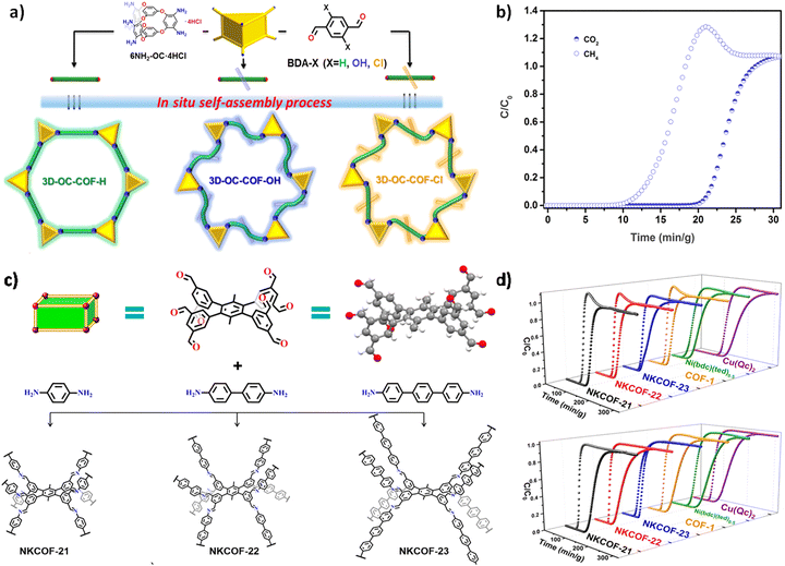 | ||
Fig. 10 (a) Strategy for constructing 3D-OC-COF. (b) Experimental breakthrough curves for CO2/CH4 (50![[thin space (1/6-em)]](https://www.rsc.org/images/entities/char_2009.gif) : :![[thin space (1/6-em)]](https://www.rsc.org/images/entities/char_2009.gif) 50, v/v) of 3D-OC-COF-OH at room temperature (reproduced from ref. 110 with permission from Chinese Chemical Society, Copyright 2021). (c) Strategy for constructing NKCOF-21, NKCOF-22, and NKCOF-23. (d) Experimental breakthrough curves for C2H4/C2H6 (1 50, v/v) of 3D-OC-COF-OH at room temperature (reproduced from ref. 110 with permission from Chinese Chemical Society, Copyright 2021). (c) Strategy for constructing NKCOF-21, NKCOF-22, and NKCOF-23. (d) Experimental breakthrough curves for C2H4/C2H6 (1![[thin space (1/6-em)]](https://www.rsc.org/images/entities/char_2009.gif) : :![[thin space (1/6-em)]](https://www.rsc.org/images/entities/char_2009.gif) 1 and 1 1 and 1![[thin space (1/6-em)]](https://www.rsc.org/images/entities/char_2009.gif) : :![[thin space (1/6-em)]](https://www.rsc.org/images/entities/char_2009.gif) 9, v/v) mixtures of different adsorbents at 298 K and 1 bar (reproduced from ref. 84 with permission from American Chemical Society, Copyright 2022). 9, v/v) mixtures of different adsorbents at 298 K and 1 bar (reproduced from ref. 84 with permission from American Chemical Society, Copyright 2022). | ||
In the same year, Zhang and co-workers successfully developed a new 8-connected building unit and reacted it with various linear diamine linkers to generate 3D COFs with bcu topology.84 Gas adsorption experiments demonstrated that all the COFs showed higher adsorption capacities for ethane (C2H6) compared to ethylene (C2H4). In single-component adsorption experiments at 298 K and 1 bar, the adsorption capacities of NKCOF-21, NKCOF-22, NKCOF-23 for C2H4 at 298 K and 1 bar were 74.3 cm3 g−1, 40.7 cm3 g−1, and 51.0 cm3 g−1, respectively, while the adsorption capacity for C2H6 reached 97.9 cm3 g−1, 65.9 cm3 g−1, and 60.5 cm3 g−1, respectively (Fig. 10c). In the entire pressure range, these COFs exhibited higher adsorption capacities for C2H6 than C2H4. Subsequently, breakthrough experiments were carried out to thoroughly assess the separation efficiency of these COFs. The results showed that NKCOF21, NKCOF-22, and NKCOF-23 could selectively desorb C2H4 with ultrahigh purity (exceeding 99.99%), while C2H6 breakthrough occurred after 40, 20, and 15 minutes, respectively (Fig. 10d). This study provided novel adsorbents for the separation of C2H6/C2H4.
Later, Peng and co-workers designed and synthesized ZJUT-2 and ZJUT-3 based on an 8-connected tetrahedral building unit derived from pyrene.86 These COFs possessed a 2-fold interpenetrated bcu net with unique pore architectures and exposed aromatic surfaces, resulting in excellent gas adsorption and separation performance. In experiments, ZJUT-2 and ZJUT-3 exhibited relatively high adsorption capacities for acetylene (C2H2) and CO2, surpassing their adsorption capacity for CH4. The adsorption capacity order was C2H2 > CO2 > CH4, with ZJUT-3 showing the highest adsorption capacity for C2H2. The selectivity of ZJUT-2 and ZJUT-3 for C2H2/CH4 and C2H2/CO2 binary mixtures was evaluated using the Ideal Adsorbed Solution Theory (IAST). At 1 atmosphere pressure, the selectivity of ZJUT-2 for C2H2/CH4 and C2H2/CO2 was determined to be 13.8 and 3.1, respectively, while ZJUT-3 exhibited selectivity of 48.2 for C2H2/CH4 and 3.2 for C2H2/CO2.
In 2023, Wang et al. successfully synthesized a large-sized single crystal 3D-TMTAPB-COF by strategically incorporating spatial steric hindrance to precisely control the precursor conformation.106 The BET surface area of 3D-TMTAPB-COF was calculated to be 940 m2 g−1, with a primary pore size distribution centered around 0.84 nm. Considering the microporous structure and narrowly distributed pore sizes of 3D-TMTAPB-COF, the researchers utilized it for the separation and enrichment of sulfur hexafluoride (SF6) from SF6/N2 mixtures. Experimental results demonstrated that 3D-TMTAPB-COF exhibited high adsorption capacities for SF6 at 273 K and 298 K, measuring 81.2 cm3 g−1 and 60.9 cm3 g−1, respectively. In contrast, its adsorption capacity for N2 was weaker. By applying the IAST, the separation selectivity of SF6/N2 (10![[thin space (1/6-em)]](https://www.rsc.org/images/entities/char_2009.gif) :
:![[thin space (1/6-em)]](https://www.rsc.org/images/entities/char_2009.gif) 90) at 298 K was predicted. The results showed that at 1 bar and 298 K, the selectivity of SF6/N2 reached 335, surpassing that of most crystalline porous materials. By fitting the experimental data to the virial equation, the Qst for SF6 and N2 were calculated. The results indicated a stronger affinity between 3D-TMTAPB-COF and SF6, with a Qst value of 33.5 kJ mol−1. This further supports the potential application of 3D-TMTAPB-COF in SF6/N2 separation.
90) at 298 K was predicted. The results showed that at 1 bar and 298 K, the selectivity of SF6/N2 reached 335, surpassing that of most crystalline porous materials. By fitting the experimental data to the virial equation, the Qst for SF6 and N2 were calculated. The results indicated a stronger affinity between 3D-TMTAPB-COF and SF6, with a Qst value of 33.5 kJ mol−1. This further supports the potential application of 3D-TMTAPB-COF in SF6/N2 separation.
Recently, Fang and co-workers designed and synthesized two 3D COFs featuring a nia net structure, named JUC-641 and JUC-642, through the combination of a sterically hexa-connected monomer based on triptycene and a planar hexa-connected monomer.98 Benefiting from the abundant isolated π-systems, ideal pore dimensions, and highly interconnected pore networks present in JUC-641 and -642, both COFs exhibited remarkable separation capacities for benzene (Bz) and cyclohexane (Cy). At a relative pressure of P/P0 = 0.95, the Bz vapor adsorption capacities of JUC-641 and JUC-642 were measured at 566 mg g−1 and 582 mg g−1, respectively. Under identical temperature and pressure conditions, the adsorption capacities for Cy vapor were found to be 293 mg g−1 and 287 mg g−1, respectively. Breakthrough experiments conducted at 298K using an equimolar Bz and Cy mixture further demonstrated that both COFs possess a higher affinity towards Bz over Cy. The actual Bz/Cy selectivities (1.80 and 1.91) were in agreement with the ideal selectivity (1.93 and 2.02), underscoring the enhanced separation efficiency of these COFs for Bz over Cy (Fig. 11).
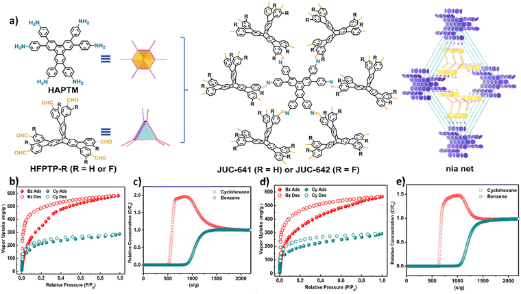 | ||
Fig. 11 (a) Strategy for constructing JUC-641 and JUC-642 with the nia topology. (b) and (d) Vapor adsorption (filled)–desorption (empty) isotherms of Bz and Cy for JUC-641 and JUC-642 b at 298 K. (c) and (e) Experimental breakthrough curves for Bz and Cy (1![[thin space (1/6-em)]](https://www.rsc.org/images/entities/char_2009.gif) : :![[thin space (1/6-em)]](https://www.rsc.org/images/entities/char_2009.gif) 1, v/v) mixtures of JUC-641 and JUC-642 at 298 K (reproduced from ref. 98 under a Creative Commons Attribution 4.0 International License. Copyright 2024, Springer Nature). 1, v/v) mixtures of JUC-641 and JUC-642 at 298 K (reproduced from ref. 98 under a Creative Commons Attribution 4.0 International License. Copyright 2024, Springer Nature). | ||
Subsequently, Negishi and co-workers prepared the first (8,8)-connected 3D COF, named TUS-88, with a bcu net by linking 8-aldehyde building units with D4h symmetric tetragonal prism nodes to 8-amino building units with D2h symmetric tetragonal prismatic nodes.116 Given the rich π-aromatic conjugation system and aromatic benzene rings in TUS-88, they investigated its potential for the separation of benzene (Bz) and cyclohexane (Cy). Experimental results demonstrated that TUS-88 exhibited a maximum adsorption capacity of 464 cm3 g−1 for Bz and 224 cm3 g−1 for Cy, with an ideal Bz/Cy selectivity of 2.07. This selectivity was further validated in breakthrough experiments using a 1![[thin space (1/6-em)]](https://www.rsc.org/images/entities/char_2009.gif) :
:![[thin space (1/6-em)]](https://www.rsc.org/images/entities/char_2009.gif) 1 (v/v) mixture of Bz and Cy. The results indicated that TUS-88 showed a strong adsorption preference for Bz, allowing high-purity Cy to be eluted first from the separation column with an effective time interval of 75.4 min g−1 and a breakthrough selectivity of 2.46 for Bz/Cy.
1 (v/v) mixture of Bz and Cy. The results indicated that TUS-88 showed a strong adsorption preference for Bz, allowing high-purity Cy to be eluted first from the separation column with an effective time interval of 75.4 min g−1 and a breakthrough selectivity of 2.46 for Bz/Cy.
5.3. Adsorption and release in the liquid phase
In 2020, Fang et al. developed a type of large-pore 3D COF with stp topology, JUC-564, using aldehyde derivatives of triptycene as the 6-connecting building units (Fig. 12a).73 JUC-564 exhibited a high surface area (3383 m2 g−1) and a record-breaking low density (0.108 g cm−3), along with an ultra-large pore size of 43 Å (Fig. 12b). This enabled JUC-564 to effectively absorb myoglobin (Mb) with dimensions of approximately 21 Å × 35 Å × 44 Å, reaching a capacity of 6.1 μmol g−1. In comparison, the microporous COF-320, with its smaller pore size (approximately 12 Å), did not show observable adsorption of Mb. In another work by Fang et al., using two different 8-connecting building units, they synthesized two 3D COFs, JUC-588 and JUC-589, with different pore size distributions.76 Characterized by N2 adsorption and determined by non-local density functional theory (NLDFT), JUC-588 exhibited a narrow pore size distribution centered at 17 Å, while JUC-589 showed the main mesopore distributions at 21 Å and 23 Å. As a result, the mesoporous JUC-589 demonstrated an exceptional ability to adsorb the dye molecule, Coomassie brilliant blue R250 (R250) with dimensions of approximately 21 Å × 18 Å × 6 Å, achieving a maximum adsorption capacity of approximately 185.7 mg g−1, while JUC-588, due to its microporous channels, had almost no adsorption of R250 molecules.
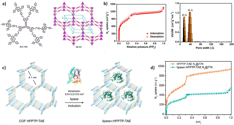 | ||
| Fig. 12 (a) Strategy for constructing JUC-564 with the stp topology. (b) N2 isotherm at 77 K and pore size distribution for JUC-564 (reproduced from ref. 73 with permission from American Chemical Society, Copyright 2020). (c) The diagram of including lipase in the COF HFPTP-TAE. (d) Comparison of N2 adsorption–desorption isotherms for COF HFPTP-TAE with lipase ⊂ HFPTP-TAE (reproduced from ref. 107 with permission from American Chemical Society, Copyright 2023). | ||
Recently, Osamu and co-workers successfully synthesized two highly crystalline mesoporous 3D COFs, named COF-HFPTP-TAE and COF-HFPTP-DMeTAB, through the strategic use of aniline as a modulator.107 Both COFs exhibit permanent porosity as well as high thermal and chemical stability. Among them, COF-HFPTP-TAE with mesopores (41 Å) (Fig. 12d) can be well encapsulated by lipase PS, with a loading capacity of 0.28 g g−1 (Fig. 12c). The lipase ⊂ HFPTP-TAE composite (⊂ refers to “include in”) has good thermal stability, extensive solvent tolerance, and can efficiently catalyse the alcoholysis of aspirin methyl ester (AME).
In 2022, Negishi et al. developed TUS-84, a 3D COF with scu-c topology, which achieved efficient loading and controlled release of ibuprofen and captopril.117 TUS-84 exhibited a loading capacity of 16 wt% for captopril, with 98% of the drug released from TUS-84 after 5 days. For ibuprofen, TUS-84 demonstrated a release rate of only 24% after 12 hours of loading and approximately 35% after 5 days. This sustained ibuprofen formulation allows for continuous drug release at a reduced dosing frequency, ensuring more consistent control over long-term pain.
In 2023, Beng et al. designed a groundbreaking 3D COF, named TUS-64, featuring a non-interpenetrated stp net. Remarkably, TUS-64 exhibits the largest pore size (47 Å) and an ultra-low density of 0.106 g cm−3.118 Due to its high specific surface area and large pore structure, TUS-64 was subjected to in vitro delivery experiments to investigate its delivery performance for five different drugs. The results demonstrated that TUS-64 successfully loaded five drugs including captopril, ibuprofen, isoniazid, 5-fluorouracil, and bromocriptine, with loadings of 14.71, 11.40, 17.37, 17.34, and 4.09 wt%, respectively. Drug release experiments revealed that TUS-64 exhibited excellent controlled release and sustained delivery for captopril, ibuprofen, isoniazid, 5-fluorouracil, and bromocriptine. For instance, in the captopril release experiment, TUS-64 released approximately 86% of the drug after 12 hours, and around 92% of the drug after 2 days. In the ibuprofen delivery experiment, TUS-64 released approximately 40% of the drug after 12 hours, and about 67% of the drug after 6 days. These results demonstrated the excellent drug delivery performance of TUS-64, including sustained delivery, controlled release, and site-specific targeting.
5.4. Heterogeneous catalysis
In 2022, Huang and co-workers successfully developed a novel 3D COF with a unique she topology, TAPP-HFPB-COF, constructed from 4-connected TAPP units and 6-connected HFPB units.79 Benefiting from its high crystallinity, excellent porosity, and good stability, they explored the application of TAPP-HFPB-COF as a photocatalyst for the alpha-functionalization of aldehydes and the photocatalytic reduction of CO2. The study found that TAPP-HFPB-COF could generate the desired products with a high yield of 89%. Compared to other catalysts, including 2D H2Por-COF, H2TPP, and some common organic dyes such as fluorescein, eosin Y, rose Bengal, and methylene blue, TAPP-HFPB-COF exhibited the best catalytic performance. This was attributed to the active sites provided by the open porphyrin moieties and the confinement effect of the 3D COF. It is worth mentioning that TAPP-HFPB-COF showed good recyclability in multiple cycles. Additionally, Huang et al. also investigated the performance of TAPP-HFPB-COF in the photocatalytic CO2 reduction reaction. The results showed that under visible light irradiation, TAPP-HFPB-COF produced CO as the major product, along with a small amount of CH4. The yields of CO and CH4 gradually increased over time and reached maximum values of 128 and 5 μmol g−1, respectively, after 6 hours. The selectivity towards CO was as high as 96%, and TAPP-HFPB-COF retained its activity and selectivity for more than ten cycles.
Based on the she topology, Lei and co-worker synthesized two innovative COFs, NJU-318 and NJU-319Fe, by linking HFPTP-triphenylene units with iron-porphyrin- or pyrene-based units.80 Under mild conditions, the hexaphenyl-triphenylene motifs within the COFs underwent a transformation into π-conjugated hexabenzo-trinaphthylene, resulting in the formation of the cyclized 3D COFs (Fig. 13a). These cyclized frameworks demonstrated enhanced absorption of visible light and significantly improved CO2 photoreduction performance, positioning them as promising materials for photochemical applications. In subsequent photocatalytic studies, the optimized photocatalyst pNJU-319Fe showed significantly enhanced photocatalytic activity, with CO production as high as 688 μmol g−1 after prolonged visible light irradiation. In contrast, NJU-319Fe produced relatively lower CO (165 μmol g−1) (Fig. 13b). pNJU-319Fe exhibited remarkable durability, maintaining its photocatalytic performance even after five consecutive cycles. Post-photocatalysis analysis, including XRD and BET measurements, confirmed its high structural stability, reinforcing its robustness and effectiveness in CO2 photoreduction systems.
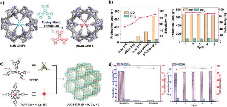 | ||
| Fig. 13 (a) Post-synthetic annulation of NJU-319Fe. (b) Photocatalytic performances comparison among NJU-318, pNJU-318, NJU-319, NJU-319Fe, and pNJU-319Fe and cyclic stability tests of NJU-319Fe (reproduced from ref. 80 with permission from American Chemical Society, Copyright 2023). (c) Strategy for constructing JUC-640-M with the stp topology. (d) Comparison of the photocatalytic activity of JUC-640-M and durability assessments of JUC-640-Co (reproduced from ref. 112 with permission from American Chemical Society, Copyright 2023). | ||
In 2023, Fang et al. successfully synthesized a novel series of 3D COFs (JUC-640-M) based on the stp net and porphyrin functionalization (Fig. 13c).112 Among these, the metal-free JUC-640-H, in particular, exhibited a low crystal density, large pore size, high surface area, and abundant exposed porphyrin active sites. Upon metal post-modification, JUC-640-M is poised to serve as a promising platform for photocatalytic applications. Supported by the interpenetrating porous structure, abundant exposure of porphyrin active sites, and appealing photoelectric properties, JUC-640-M has been employed for photocatalytic CO2 reduction. The experiments demonstrated that JUC-640-Co exhibited remarkably high CO yield (15.1 mmol g−1 h−1) and selectivity (94.4%), setting a new record for COF-based catalysts (Fig. 13d).
Zhang and co-workers successfully synthesized a new type of porphyrin building unit with a cubic structure and eight connection points.85 By combining these building units with linear amine building units, they obtained two 3D COFs called NUST-5 and NUST-6 with a interpenetrated pcb topology. Using these COFs, the researchers conducted light-induced CO2 reduction experiments without the involvement of metals. After 10 hours of visible light irradiation, the CO production rates reached 54.7 μmol g−1 for NUST-5 and 76.2 μmol g−1 for NUST-6, respectively. Notably, the CH4 production rates remained relatively low at 17.2 μmol g−1 for NUST-5 and 12.8 μmol g−1 for NUST-6. In terms of selectivity, the CO/CH4 ratios were impressive, standing at 76% for NUST-5 and 86% for NUST-6. These values rank among the highest selectivity levels ever reported for photocatalytic CO2 reduction, whether using COFs or other metal-free catalysts, highlighting their remarkable efficiency.
Considering the large cyclic conjugated structure of porphyrin molecules, they can be used to synthesize photosensitizers to generate reactive oxygen species (ROS). Zheng et al. reacted an 8-connecting building unit (DPTB-Me) with a 4-connecting porphyrin unit (TAPP-X) to construct two 3D COFs with an scu net, namely NKCOF-25-H and NKCOF-25-Ni (Fig. 14a).99 The diffuse reflectance spectra (DRS) showed broad visible light absorption bands for both COFs, with optical bandgaps of 1.76 eV and 1.78 eV, meeting the requirements of heterogeneous photocatalysts. Furthermore, electrochemical Mott–Schottky spectroscopy and transient photocurrent response curves were measured to further demonstrate the photocatalytic potential of NKCOF-25-X. They were applied in the cyclization reaction of tertiary aniline and maleimide, as well as the photocatalytic aerobic oxidation coupling of amines. The results indicated that both COFs efficiently generated superoxide radical anions (O2˙−) under visible light and air conditions, achieving high yields of 90–99% in the cyclization of tertiary aniline and maleimide, as well as the oxidation coupling of amines (Fig. 14b). Additionally, NKCOF-25-X exhibited excellent size selectivity and higher turnover frequency (TOF).
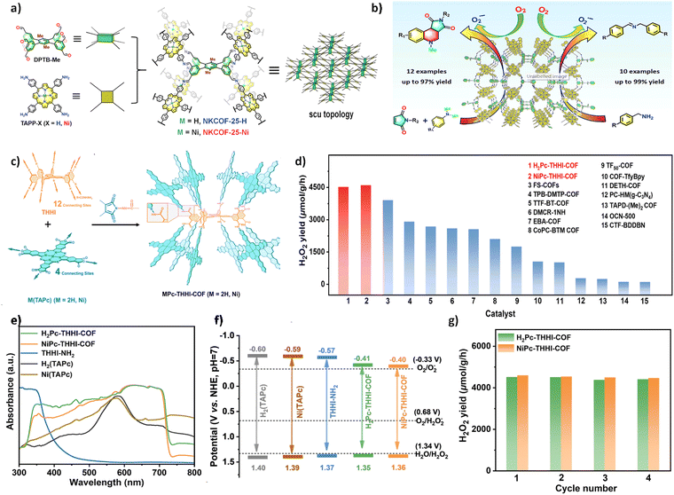 | ||
| Fig. 14 (a) Strategy for constructing NKCOF-25-M with the scu topology. (b) Substrate scope expansion for the cycloaddition reaction between tertiary aniline and maleimide (reproduced from ref. 99 with permission from Elsevier Inc, Copyright 2022). (c) Strategy for constructing MPc-THHI-COF. (d) Photocatalytic H2O2 production rates of H2Pc-THHI-COF and NiPc-THHI-COF in comparison with reported COF-based photocatalysts. (e) UV/Vis-DRS analysis of MPc-THHI-COFs, THHI-NH2, and M(TAPc) (M = H2, Ni). (f) Band gaps of MPc-THHI-COFs, THHI-NH2, and M(TAPc) (M = H2, Ni). (g) Stability tests of H2Pc-THHI-COF and NiPc-THHI-COF (reproduced from ref. 88 with permission from American Chemical Society, Copyright 2024). | ||
Similar to porphyrins, phthalocyanines (Pcs) feature a distinctive conjugated 18π electron macrocycle structure, which has found extensive applications in organic electroluminescence, catalysis, and optoelectronics. Recently, Jiang and co-worker synthesized phthalocyanine-based MPc THHI COFs (M = H2, Ni) with 12 connection points through the reaction between M (TAPc) (M = H2, Ni) and THHI (Fig. 14c).88 These MPc-THHI COFs exhibited a broadened visible light absorption range and a narrowed optical band gap (Fig. 14e and f). As photocatalysts for H2O2 production, MPc-THHI-COFs (M = H2, Ni) demonstrated remarkable efficiency under visible light irradiation (λ > 400 nm) in pure water and O2, without the use of sacrificial agents, as illustrated in Fig. 14d. This exceptional photocatalytic performance underscores their potential in sustainable H2O2 generation, driven solely by light and oxygen. The rates of H2O2 production were 4511 and 4589 μmol h−1 g−1, respectively, surpassing most of the photocatalysts reported to date (Fig. 14g). Furthermore, MPc-THHI COFs (M = H2, Ni) also exhibited excellent photocatalytic durability, maintaining a good production rate across four consecutive reaction cycles in H2O.
Subsequently, Jiang and co-worker successfully synthesized a series of 3D COFs with 2-fold interpenetrated scu or sqc topologies, termed POSS-MTFPP-COF, by reacting the 8-connected POSS(NH2)8 with the 4-connected MTFPP, (M = Co, Zn, Ni, 2H) (Fig. 15a).102 Notably, the central ion in the porphyrin can precisely control the structure and functionality of the COF. Given these unique structural features, the researchers explored the photocatalytic CO2 reduction performance of these materials. The results demonstrated that under visible light irradiation, POSS-NiTFPP-COF-sqc exhibited the highest catalytic performance, with a CO production rate of 9680 mmol g−1 h−1 and a selectivity of 97%, significantly outperforming the other three COFs (Fig. 15b).This superior performance is likely attributed to the weak interactions between the two interpenetrated frameworks in the sqc topology, which effectively act as a single entity, facilitating the migration of photogenerated electrons between them. This hypothesis was further supported by subsequent photocurrent response measurements and electrochemical impedance spectroscopy (EIS) tests, where POSS NiTFPP COF-sqc showed stronger photocurrent and faster charge transfer than the other COFs.
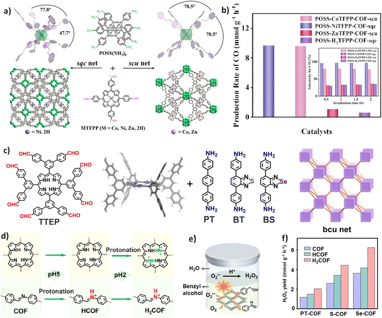 | ||
| Fig. 15 (a) Strategy for constructing POSS-MTFPP-COF with sqc and scu topologies. (b) The average CO production rates of POSS CoTFPP-COF-scu, POSS NiTFPP-COF-sqc, POSS ZnTFPP-COF-scu, and POSS-H2TFPP-COF-sqc, along with their CO selectivity under different times (reproduced from ref. 102 with permission from Wiley-VCH, Copyright 2024). (c) Schematic diagram of the building units and topologies of PT-COFs, S-COFs, and Se-COFs. (d) Diagram of the stepwise protonation process of the 3D-bcu-COF. (e) Schematic diagram of the 3D-bcu-COF used for photocatalytic H2O2 production. (f) The H2O2 production rates for PT-COF, S-COF, and Se-COF, as well as their rates after stepwise protonation, during photocatalytic reactions (reproduced from ref. 119 with permission from Wiley-VCH, Copyright 2024). | ||
In a recent study, Lei and co-worker synthesized PT-COFs, S-COFs, and Se-COFs by connecting 8-connected aldehyde porphyrin building units with linear building units functionalized with phenyl, benzothiadiazole, or benzoselenadiazole groups via imine linkages (Fig. 15c).119 Given the well-exposed porphyrin and imine sites in the 3D-bcu-COF, they employed a stepwise post-modification approach to optimize its photocatalytic activity (Fig. 15d). Among these, the doubly protonated H2Se-COF, containing benzoselenadiazole functional groups, exhibited the most outstanding visible light absorption and charge separation capabilities. They then applied the optimized photocatalyst to photocatalytic H2O2 production coupled with benzyl alcohol oxidation to benzaldehyde under visible light irradiation (λ > 420 nm) (Fig. 15e). The H2O2 production rate of Se-COF reached 3.6 mmol g−1 h−1, outperforming that of S-COF (2.6 mmol g−1 h−1) and PT-COF (1.2 mmol g−1 h−1). Further protonation of H2Se-COF increased the H2O2 yield to 6.1 mmol g−1 h−1 (Fig. 15f). Under identical testing conditions, this performance represents the highest recorded for COF-based photocatalysts, highlighting the advantages of dual functionalization in the design of effective photocatalysts.
In a different approach, Zhang and co-worker designed a porphyrin as an 8-connected cubic node and reacted it with tetra(4-aminophenyl) methane (TAPM) through a Schiff base reaction to construct two types of microporous three-dimensional POR-COFs for electrocatalytic cathodic nitrogen reduction reactions (NRRs).101 Notably, after post-synthetic modification by coordinating transition metal ions, iron and copper, to the centers of the porphyrin units, the 3D COF with Fe–N4 catalytic centers achieved a significantly higher ammonia yield and faradaic efficiency (94.26 ± 4.9 μg h−1 mg−1 and 18.37 ± 0.96%, at −0.5 V vs. RHE, reversible hydrogen electrode) compared to the COF with Cu–N4 centers. This highlights the significant impact of the central metal within the porphyrin node on the catalytic activity and efficiency of the 3D COFs in the NRR process.
5.5. Lithium sulfur batteries
In recent years, 2D COFs have attracted substantial attention as active materials across various energy storage devices, including solar cells,121,122 lithium-ion batteries,123–125 and supercapacitors.126,127 However, 1D pore channels formed by the dense packing of 2D COF layers may lead to the burial of active sites, which to some extent limits their electrochemical performance, especially in electrocatalysis and energy storage. In contrast, 3D COFs generally exhibit interconnected porous architectures, larger surface areas, and fully exposed active sites, all of which facilitate efficient mass transport and ensure the maximum utilization of active sites. However, the scarcity of sufficient conjugated 3D building units means that conjugated 3D COF materials are still rare.In 2022, Jiang et al. synthesized a 3D-scu-COF based on the building unit of 8-connected octahedral DMOPTP with a 3D fully aromatic conjugated structure and the building units of 4-connected square planar conjugated TAPPy and H2TAP.81 The highly conjugated framework structure resulted in excellent conductivity of 3D-scu-COF-1 and 3D-scu-COF-2 (3.2–3.5 × 10⁻⁵ S cm−1). Additionally, the rigid 3D tetragonal prism shape of DMOPTP directed the formation of a 2-fold interpenetrated scu topology with high porosity (Fig. 16a). This structure endowed the material with an impressive sulfur adsorption capacity, as evidenced by the sulfur content in S@3D-scu-COF-1 and S@3D-scu-COF-2, which reached 70 wt% and 68 wt%, respectively. Moreover, this architecture facilitated effective interaction with lithium polysulfides (LiPS), enhancing the material's performance in related applications. 3D-scu-COFs have emerged as highly promising sulfur hosts for lithium-sulfur batteries (LSBs). These materials exhibit exceptional capacity, ranging from 1035 to 1155 mA h g−1 at 0.2 C (where 1675 mA g−1 at 1 C) (Fig. 16b), along with excellent rate capabilities, sustaining capacities of 713 to 757 mA h g−1 at 5.0 C. Furthermore, they demonstrate remarkable cycling stability, retaining 71–83% of their capacity after 500 cycles at 2.0 C.
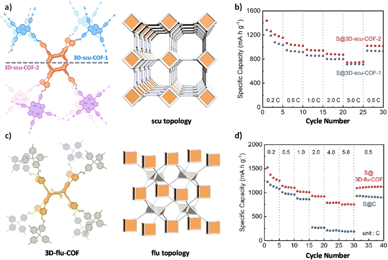 | ||
| Fig. 16 (a) Strategy for constructing 3D-scu-COF-1 and 3D-scu-COF-2 with the scu topology. (b) Rate performance comparison of S@3D-scu-COF-1 and S@3D-scu-COF-2 electrodes at different rates (reproduced from ref. 81 with permission from American Chemical Society, Copyright 2022). (c) Strategy for constructing 3D-flu-COF with the flu topology. (d) Rate performance comparison of S@ 3D-flu-COF and S@ C electrodes at different rates (reproduced from ref. 128 with permission from American Chemical Society, Copyright 2023). | ||
Subsequently, Jiang et al. synthesized 3D-flu-COF with a non-interpenetrated flu net by replacing the square planar building units with a Td tetrahedral linker of TAM128 (Fig. 16c). This COF exhibited an impressive BET surface area of 2204 m2 g−1, featuring large octahedral cavities (4.6 nm) and a network of interconnected pores. These structural characteristics facilitated a high sulfur loading capacity of 0.845 mmol g−1, enhanced LiPS adsorption capabilities, and promoted efficient ion diffusion. When employed as a cathode material for LSBs, the 3D-flu-COF delivered an outstanding specific capacity of 1249 mA h g−1 at a current density of 0.2 C (Fig. 16d). With increasing current density at 0.5, 1.0, 2.0, 4.0, and 5.0 C, the specific capacity slightly decreased to 1102, 1092, 1280, 2902, and 764 mA h g−1, respectively, indicating its excellent rate performance. Furthermore, electrochemical tests conducted at a higher sulfur loading of 4.5 mg cm−2 demonstrated the outstanding performance of the 3D-flu-COF electrode. At a current density of 0.2 C, the 3D-flu-COF-4.5 electrode delivered both high specific capacity (1181 mA h g−1) and area capacity (5.3 mA h cm−2). Even after 100 cycles, the 3D-flu-COF-4.5 electrode retained 85% of its initial capacity. These results suggest the potential application prospects of high-connectivity 3D COFs in the field of lithium-sulfur batteries.
Yu and co-workers have recently advanced the field of solid electrolytes for lithium-ion batteries by creating a series of crystalline 3D COFs based on polyhedral oligomeric silsesquioxane (POSS).82 These COFs feature the and scu topological structures and have been applied as lithium-ion conducting solid electrolytes in solid-state batteries. Their research demonstrates that these POSS-based COFs can achieve high ionic conductivities up to 1.23 × 10⁻⁴ S cm−1, a high Li+ transference number of 0.86, and stable cyclic performance with 93% capacity retention in a Li metal battery (Li/NCM523). The study highlights the influence of the chemical structure, crystallinity, porosity, and topological structure of the building units on the ionic conductivity of the COFs. It was found that the COFs with the topology, specifically POSS-TPA-COF and POSS-TFPB-COF, exhibited higher ionic conductivities than those with scu topology, namely POSS-TFPPyCOF and POSS-HPB-COF. The reported ionic conductivities for these materials are as follows: POSS-TPA-COF at 1.23 × 10⁻⁴ S cm−1, POSS-TFPB-COF at 7.23 × 10⁻⁵ S cm−1, POSS-TFPPy-COF at 3.64 × 10⁻⁵ S cm−1, and POSS-HPB-COF at 4.94 × 10⁻⁵ S cm−1. This work underlines the potential of POSS-based COFs in the development of solid-state lithium batteries, showcasing the importance of structural consideration for enhancing the performance of solid electrolytes in terms of ionic conductivity, Li+ transference number, and battery cycling stability.
5.6. Charge transport
The structure and performance of COFs are directly related to the connectivity and symmetry of the building units. In general, 2D COFs formed by aggregation of coplanar 2D polygonal building units exhibit interlayer π–π stacking, allowing for the efficient movement of charge carriers. On the other hand, the aggregation of non-coplanar 2D polygonal building units or 3D polyhedral building units generates 3D COFs, where the lack of π–π interactions makes charge transfer more challenging. From the perspective of building unit connectivity, in 2017, Wang et al. achieved the formation of anionic tetrahedral COFs through ester exchange reactions between hydroxyl groups and trimethylborate (B(OMe)3).34 By introducing counterions (lithium ion (Li+), dimethylammonium (HDMA+), or protonated piperazine (H2PPZ2+)), they constructed anionic cyclodextrin(Y-CD)-based 3D COFs. When loaded with organic liquid electrolyte (lithium hexafluorophosphate (LiPF6), 1 M in ethylene carbonate (EC)/dimethyl carbonate (DMC) at a volume ratio of 1![[thin space (1/6-em)]](https://www.rsc.org/images/entities/char_2009.gif) :
:![[thin space (1/6-em)]](https://www.rsc.org/images/entities/char_2009.gif) 1), the CD-COF-Li exhibited a Li+ conductivity of 2.7 × 10⁻³ S cm−1 at 30 °C, which can be attributed to the anionic framework generated by spiral borate salt bonds and the flexibility and dynamic nature induced by cyclodextrin. This value represents one of the highest reported lithium-ion conductivities among crystalline porous materials, including COFs and MOFs. Inspired by this, Xu et al. applied CD-COF Li to solid-state electrolyte (SSE) in rechargeable solid-state lithium–oxygen (Li–O2) batteries (Fig. 17a).129 The prepared CD-COF-Li-SSE showed excellent ion conduction characteristics (s = 2.73 × 10⁻³ S cm−1 and Ea = 0.18 eV) (Fig. 17b). Through two-dimensional exchange nuclear magnetic resonance spectroscopy (2D-EXSY NMR), the transport time scale of distinguishable lithium-ion sites in the solid-state CD-COF-Li-SSE was thoroughly investigated, revealing critical insights into the ion transport mechanisms of porous COFs. Notably, solid-state Li-O2 batteries incorporating CD-COF-Li demonstrated an exceptional specific capacity of 9340 mA h g−1 and achieved a record cycle life of 100 cycles. These results provide a foundational understanding for the development of COFs as highly efficient lithium-ion conductors in solid-state battery technologies, highlighting their potential to revolutionize next-generation energy storage systems (Fig. 17c).
1), the CD-COF-Li exhibited a Li+ conductivity of 2.7 × 10⁻³ S cm−1 at 30 °C, which can be attributed to the anionic framework generated by spiral borate salt bonds and the flexibility and dynamic nature induced by cyclodextrin. This value represents one of the highest reported lithium-ion conductivities among crystalline porous materials, including COFs and MOFs. Inspired by this, Xu et al. applied CD-COF Li to solid-state electrolyte (SSE) in rechargeable solid-state lithium–oxygen (Li–O2) batteries (Fig. 17a).129 The prepared CD-COF-Li-SSE showed excellent ion conduction characteristics (s = 2.73 × 10⁻³ S cm−1 and Ea = 0.18 eV) (Fig. 17b). Through two-dimensional exchange nuclear magnetic resonance spectroscopy (2D-EXSY NMR), the transport time scale of distinguishable lithium-ion sites in the solid-state CD-COF-Li-SSE was thoroughly investigated, revealing critical insights into the ion transport mechanisms of porous COFs. Notably, solid-state Li-O2 batteries incorporating CD-COF-Li demonstrated an exceptional specific capacity of 9340 mA h g−1 and achieved a record cycle life of 100 cycles. These results provide a foundational understanding for the development of COFs as highly efficient lithium-ion conductors in solid-state battery technologies, highlighting their potential to revolutionize next-generation energy storage systems (Fig. 17c).
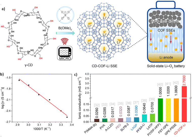 | ||
| Fig. 17 (a) Preparation strategy for integrated solid-state lithium-ion batteries with CD-COF-Li electrolyte. (b) Ionic conductivities of CD-COF-Li. (c) Comparison of ionic conductivity between CD-COF-Li and other solid-state electrolytes in Li–O2 batteries (reproduced from ref. 129 with permission from Elsevier Inc, Copyright 2023). | ||
Mateo-Alonso and co-workers have successfully synthesized 3D COFs (Marta-COF-3 and 4) with a tightly interconnected pcu topology network from twisted polycyclic aromatic hydrocarbons (3D-HBC) that possess a triangular antiprism structure.78 Due to the highly intertwined structure, similar to 2D COFs, there is interlayer π–π stacking between the frameworks based on the 3D-HBC building units. This introduction of a π system enables the charge transfer characteristics in 3D COFs. The intrinsic mobility of Marta COF-3 and COF-4, as determined through flash photolysis time-resolved microwave conductivity (FP-TRMC), is measured to be within the range of 1.2 × 10⁻⁴ to 1.3 × 10⁻⁴ cm2 V−1 s−1. This value is comparable to the highest mobility reported for 2D COFs, which typically falls between 10−5 and 10−4 cm2 V−1 s−1.
6. Challenges and future directions
In recent years, COFs have experienced significant advancements, largely driven by the rapid development of reticular chemistry.130–133 High-connectivity 3D COFs, in particular, show great promise across various applications, including energy storage, gas adsorption, catalysis, and optoelectronics. This potential arises from their intricate pore architectures, large surface areas, and numerous active sites. Fig. 18 summarizes the challenges facing high-connectivity 3D COFs, including structural diversity, challenges in structural analysis, difficulties in large-scale production, and the need for functional expansion. We also outline anticipated development directions to address these challenges.Firstly, in terms of structural diversification, the use of highly connected building units is considered an effective approach to synthesize diverse COF structures. By developing building units with a higher number of nodes, we can create more complex topologies, significantly enriching the variety of COFs. For example, by synthesizing a 12-node building unit and combining it with 4 or 6-node units, it could be possible to obtain hpt, shp, alb, and several other novel topologies of COFs (Fig. 19a). However, compared to other reticular materials like metal–organic frameworks (MOFs),134–136 where the building unit node numbers can exceed 24, COFs currently have a maximum node count of 16, indicating a gap that still needs to be addressed.
Furthermore, due to the challenges of organic synthesis and the fixed hybrid orbitals of organic molecules, it is impossible to expand the number of nodes in organic building units indefinitely. Therefore, synthesizing building units with different shapes and symmetries is equally important for expanding the structural diversity of high-connectivity 3D COFs.
We have found that highly connected organic building units, in addition to having a high number of nodes, often possess multiple organic branching points. These organic branching points can be decomposed into appropriate, independent nodes in topological analysis.137 Through this decomposition, polyhedral structures with different shapes and symmetries can be obtained. For example, an 8-connected (8-c) cubic structure with Oh symmetry can be replaced by combinations of 4-c or 3-c nodes, resulting in polyhedra with different symmetries such as D4h, D2d, D2h, and D4 (Fig. 19b). Although still limited by specific synthesis conditions, the network templates available have expanded from simple edge-transitive nets to a broader and more complex range of derived networks. Due to the differences in the types of organic branching points, and the orientations and distributions of low-symmetry polyhedra in the crystal network, these derived networks can exhibit significant differences. Even if they originate from the same parent net, these differences can lead to COFs with markedly different structural properties such as pore size, shape, and framework connectivity. For example, the scu network derived from an (8+3)-connected parent net exhibits different space groups and pore structures in its derived topologies like cut, ffc, lwg, mmm, eed, and tbo-b3 nets (Fig. 19c). Therefore, selecting an appropriate target network and carefully considering the organic branching points within the building units are key to the successful design and synthesis of high-connectivity COFs and are crucial strategies for promoting COF diversity.
Another significant challenge is structural determination of high-connectivity COFs. Due to the tendency of high-connectivity 3D COFs to form interpenetrated structures or complex topologies, traditional methods like powder X-ray diffraction (PXRD) combined with structure simulation often struggle to provide precise structural information.138–140 Although SCXRD is considered the ultimate solution to this issue,108 the difficulty in growing COF single crystals has driven researchers to seek alternative structural analysis methods. Currently, there is exploration into improving the crystallinity of COFs by adding suitable competing inhibitors, such as aniline or trifluoroethylamine,141 but the general applicability of these methods remains unresolved. To address this issue, future research could focus on developing new strategies that enhance material crystallinity, enabling the growth of larger high-connectivity COF single crystals. Additionally, the development of more advanced characterization techniques, such as HRTEM and cryo-electron microscopy, could provide a more comprehensive understanding of the microstructure of high-connectivity 3D COFs.142–146 Of course, with the advancement of computational chemistry and materials simulation technologies, the application of structural simulations in high-connectivity COF structural analysis is becoming increasingly widespread. Through molecular dynamics simulations, DFT calculations, and other methods, researchers can simulate structural changes under various conditions, predict the physicochemical properties of materials, and provide guidance for experimental studies. Particularly for interpenetrated structures or novel topologies, the use of simulation techniques can significantly enhance the accuracy of structural analysis.
Functionalization of COFs remains another major challenge. Despite the considerable potential for functionalization inherent in high-connectivity 3D COFs, research in this area is still relatively limited. Functionalization, especially concerning side groups, is often constrained by structural complexity. To address this issue, it is essential to develop highly reactive high-connectivity building units and to synthesize high-connectivity COFs with unique topologies and functionalities by introducing other building units with specific roles. This approach not only enhances the functionalization of materials but also significantly broadens the structural and application scope of 3D COFs. Moreover, the stability of COFs is crucial for their practical applicability. Current high-connectivity 3D COF synthesis primarily relies on Schiff-base reactions, which may not withstand the harsh conditions encountered in real-world applications, limiting COF utility. Thus, expanding the repertoire of high-connectivity reactions to develop functionalized COF materials with exceptional chemical stability and performance is a vital research direction for the future.
Lastly, achieving large-scale production of high-connectivity COFs poses a challenge. While traditional solvothermal methods can yield high-quality high-connectivity COFs, their complexity and limitations hinder large-scale applications. Although successful kilogram-scale COF synthesis has been reported using a melt polymerization method, this approach is applicable only to a limited number of COF types.32,147 Future research must focus on refining synthesis conditions, reaction types, and systems. By optimizing reaction conditions, it may be possible to maintain high crystallinity while increasing synthesis efficiency. Additionally, exploring novel reaction systems, such as solid-state reactions or photochemical approaches, could open new avenues for synthesizing high-connectivity 3D COFs, unlocking further potential for innovation.
7. Conclusion
In conclusion, this review provides a comprehensive exploration of the design principles underlying the topological structures of high-connectivity 3D COFs, highlighting the importance of building unit design, selection of construction strategies, and choice of suitable linkages. We trace the development process of these topological structures, unravelling the complexities of structural analysis. By emphasizing the diverse potential applications of high-connectivity 3D COFs, we focus on their pivotal roles in adsorption, separation, heterogeneous catalysis, lithium–sulfur batteries, and charge transfer processes. Furthermore, we address the various challenges and complexities faced by these materials, offering valuable insights for future research. We hope this review serves as a guiding resource for future endeavors in synthesizing novel topological structures and developing high-performance 3D COFs.Abbreviations
| 1D | One dimensional |
| 2D | Two dimensional |
| 3D | Three dimensional |
| 2D-EXSY NMR | Two-dimensional exchange nuclear magnetic resonance spectroscopy |
| 3D ED | 3D electron diffraction |
| 3D-HBC | 2,3,6,7,10,11,14,15,18,19,22,23-Dodecahydroxy-cata hexabenzocoronene |
| BET | Brunauer–Emmett–Teller |
| BPA | Borophosphonic acid |
| BT | 4,7-Bis(4-aminophenyl)-2,1,3-benzothiadiazole |
| BS | 4,4′-Benzo[c][1,2,5]-selenadiazole-4,7 diyl dianiline |
| COFs | Covalent organic frameworks |
| cRED | Continuous rotation electron diffraction |
| CPT | Hexa(4-formyl-phenoxy) cyclotriphosphazene |
| Cy | Cyclohexane |
| CzTPN-16CHO | 2,3,5,6-Tetrakis(3,6-bis(3,5-diformylphenyl)-9H-carbazol-9-yl)terephthalonitrile |
| DFT | Density functional theory |
| DHTPA | 2,5-Dihydroxyterephthalaldehyde |
| DPTB-Me | 4′,5′-Bis(3,5-diformylphenyl)-3′,6′-dimethyl-[1,1′:2′,1′′-terphenyl]-3,3′′,5,5′′-tetracarbaldehyde |
| DMC | Dimethyl carbonate |
| DMeTAB | 1,2,4,5-Tetrakis(4-aminophenyl)-3′,6′-dimethylbenzene |
| DMOPTP | 6,13-Dimethoxy-2,3,9,10,18,19,24,25-octa(4′-formylphenyl)pentiptycene |
| DRS | Diffuse reflectance spectra |
| EC | Ethylene carbonate |
| FP-TRMC | Flash photolysis time-resolved microwave conductivity |
| FBTA-8CHO | (3,6-Difluorobenzene-1,2,4,5-tetrayl)tetrakis(azanetriyl) octakis[1,1′-biphenyl]-4-carbaldehyde |
| HDIATP | 2,3,6,7,14,15-Hexa(3′,5′-diisopropyl-4′-amino) triptycene |
| HDMA+ | Dimethylammonium |
| HFPTP-triptycene | 2,3,6,7,14,15-Hexa(4′-formylphenyl) triptycene |
| HFPTP-triphenylene | 2,3,6,7,10,11-Hexakis(4-formylphenyl)triphenylene |
| HFPB | Hexa(4-formylphenyl)benzene |
| H2PPZ2+ | Protonated piperazine |
| HRTEM | High-resolution transmission electron microscopy |
| LiPSs | Lithium polysulfides |
| Li+ | Lithium ion |
| LiPF6 | Lithium hexafluorophosphate |
| Li–O2 | Lithium–oxygen |
| LSBs | Lithium–sulfur batteries |
| NRR | Nitrogen reduction reaction |
| MOFs | Metal–organic frameworks |
| OAPy | 1,3,6,8-Tetrakis 3,5-bis[(4-amino)phenyl]phenylpyrene |
| O2˙− | Superoxide radical anions |
| PyTTA | 1,3,6,8-Tetrakis(4-aminophenyl)pyrene |
| POSS | Polyhedral oligomeric silsesquioxanes |
| Pcs | Phthalocyanines |
| RCSR | Reticular Chemistry Structure Resource |
| SSE | Solid-state electrolyte |
| SCXRD | Single crystal X-ray diffraction |
| TA | 1,4-Phthalaldehyde |
| TABPM | Tetrakis(4-amino biphenyl)methane |
| TAE | Tetra-(4-aminophenyl)-ethylene |
| TAM | Tetrakis(4-aminophenyl)methane |
| TAPP | Tetrakis(4-aminophenyl)porphyrin |
| TEM | Transmission electron microscopy |
| TDFTD | 3,3′,5,5′-Tetra(3′′,5′′-diformylphenyl)-2,2′,6,6′-tetramethoxy-4,4′-dimethylbiphenyl |
| TDFCB | 2,3,5,6-Tetrakis(([3,5-diformylphenyl]-5-yl)-9H-carbazol-9-yl)-1,4-benzenedicarbonitrile |
| TFAPPM | Tetra[(2-fluoro-4-aminophenyl)-phenyl]methane |
| THHI-NH2 | 5,5′,5′′,5′′′,5′′′′,5′′′′-(Triphenylene-2,3,6,7,10,11-hexayl)hexa(isophthalohydrazide) |
| TTEP | 5,10,15,20-Tetrayl(tetrakis(([1,1′:3′,1′′-terphenyl]-4,4′′-dicarbaldehyde)))-porphyrin |
| TMTAPB | 1,3,5-Trimethyl-2,4,6-tri[3,5-di(4-aminophenyl-1-yl)phenyl-1-yl]benzene |
| TOF | Turnover frequency |
| Triptycene-12-CHO | 5′,5′′′′,5′′′′′′′,5′′′′′′′′′′,5′′′′′′′′′′′′′,5′′′′′′′′′′′′′′′′-(9,10-dihydro-[1,2]-benzenoanthracene-2,3,6,7,14,15-hexayl)hexakis[1,1′:3′,1′′-terphenyl]-4,4′′-dicarbaldehyde |
| γ-CD | Cyclodextrins |
Data availability
No primary research results, software or code have been included and no new data were generated or analysed as part of this review.Conflicts of interest
There are no conflicts to declare.Acknowledgements
This work was supported by the National Key R&D Program of China (2022YFB3704900 and 2021YFF0500500), the National Natural Science Foundation of China (22025504, 21621001, 22105082 and 2240050702), the SINOPEC Research Institute of Petroleum Processing, “111” project (BP0719036 and B17020), the China Postdoctoral Science Foundation (2023M741326 and 2023TQ0128), and the program for JLU Science and Technology Innovative Research Team.Notes and references
- C. S. Diercks and O. M. Yaghi, Science, 2017, 355, eaal1585 CrossRef.
- K. Geng, T. He, R. Liu, S. Dalapati, K. T. Tan, Z. Li, S. Tao, Y. Gong, Q. Jiang and D. Jiang, Chem. Rev., 2020, 120, 8814–8933 CrossRef CAS PubMed.
- X. Guan, F. Chen, Q. Fang and S. Qiu, Chem. Soc. Rev., 2020, 49, 1357–1384 RSC.
- S.-Y. Ding and W. Wang, Chem. Soc. Rev., 2013, 42, 548–568 RSC.
- X. Feng, X. Ding and D. Jiang, Chem. Soc. Rev., 2012, 41, 6010–6022 RSC.
- R. Mercado, R.-S. Fu, A. V. Yakutovich, L. Talirz, M. Haranczyk and B. Smit, Chem. Mater., 2018, 30, 5069–5086 CrossRef CAS.
- U. Díaz and A. Corma, Coord. Chem. Rev., 2016, 311, 85–124 CrossRef.
- S.-Y. Ding, J. Gao, Q. Wang, Y. Zhang, W.-G. Song, C.-Y. Su and W. Wang, J. Am. Chem. Soc., 2011, 133, 19816–19822 CrossRef CAS PubMed.
- R. Chen, J.-L. Shi, Y. Ma, G. Lin, X. Lang and C. Wang, Angew. Chem., Int. Ed., 2019, 58, 6430–6434 CrossRef CAS.
- K. Dey, M. Pal, K. C. Rout, S. Kunjattu H, A. Das, R. Mukherjee, U. K. Kharul and R. Banerjee, J. Am. Chem. Soc., 2017, 139, 13083–13091 CrossRef CAS.
- Z. Xiang, R. Mercado, J. M. Huck, H. Wang, Z. Guo, W. Wang, D. Cao, M. Haranczyk and B. Smit, J. Am. Chem. Soc., 2015, 137, 13301–13307 CrossRef CAS PubMed.
- H. Furukawa and O. M. Yaghi, J. Am. Chem. Soc., 2009, 131, 8875–8883 CrossRef CAS PubMed.
- Z. Wang, S. Zhang, Y. Chen, Z. Zhang and S. Ma, Chem. Soc. Rev., 2020, 49, 708–735 RSC.
- R. Kulkarni, Y. Noda, D. Kumar Barange, Y. S. Kochergin, P. Lyu, B. Balcarova, P. Nachtigall and M. J. Bojdys, Nat. Commun., 2019, 10, 3228 CrossRef PubMed.
- S.-Y. Ding, M. Dong, Y.-W. Wang, Y.-T. Chen, H.-Z. Wang, C.-Y. Su and W. Wang, J. Am. Chem. Soc., 2016, 138, 3031–3037 CrossRef CAS PubMed.
- S. Dalapati, S. Jin, J. Gao, Y. Xu, A. Nagai and D. Jiang, J. Am. Chem. Soc., 2013, 135, 17310–17313 CrossRef CAS PubMed.
- H. Li, J. Chang, S. Li, X. Guan, D. Li, C. Li, L. Tang, M. Xue, Y. Yan, V. Valtchev, S. Qiu and Q. Fang, J. Am. Chem. Soc., 2019, 141, 13324–13329 CrossRef CAS PubMed.
- Q. Hao, Z.-J. Li, C. Lu, B. Sun, Y.-W. Zhong, L.-J. Wan and D. Wang, J. Am. Chem. Soc., 2019, 141, 19831–19838 CrossRef CAS PubMed.
- F. Xu, S. Yang, X. Chen, Q. Liu, H. Li, H. Wang, B. Wei and D. Jiang, Chem. Sci., 2019, 10, 6001–6006 RSC.
- H. Peng, S. Huang, V. Montes-García, D. Pakulski, H. Guo, F. Richard, X. Zhuang, P. Samorì and A. Ciesielski, Angew. Chem., Int. Ed., 2023, 62, e202216136 CrossRef CAS PubMed.
- Y. Liu, W. Li, C. Yuan, L. Jia, Y. Liu, A. Huang and Y. Cui, Angew. Chem., Int. Ed., 2022, 61, e202113348 CrossRef CAS PubMed.
- J. Huang, X. Han, S. Yang, Y. Cao, C. Yuan, Y. Liu, J. Wang and Y. Cui, J. Am. Chem. Soc., 2019, 141, 8996–9003 CrossRef CAS PubMed.
- Y. Liu, J. Ren, Y. Wang, X. Zhu, X. Guan, Z. Wang, Y. Zhou, L. Zhu, S. Qiu, S. Xiao and Q. Fang, CCS Chem., 2023, 5, 2033–2045 CrossRef CAS.
- W. Xian, P. Zhang, C. Zhu, X. Zuo, S. Ma and Q. Sun, CCS Chem., 2021, 3, 2464–2472 CrossRef CAS.
- J. Li, X. Jing, Q. Li, S. Li, X. Gao, X. Feng and B. Wang, Chem. Soc. Rev., 2020, 49, 3565–3604 RSC.
- X. Xu, S. Zhang, K. Xu, H. Chen, X. Fan and N. Huang, J. Am. Chem. Soc., 2023, 145, 1022–1030 CrossRef CAS PubMed.
- A. P. Côté, A. I. Benin, N. W. Ockwig, M. O'Keeffe, A. J. Matzger and O. M. Yaghi, Science, 2005, 310, 1166–1170 CrossRef PubMed.
- Y. Li, W. Chen, G. Xing, D. Jiang and L. Chen, Chem. Soc. Rev., 2020, 49, 2852–2868 RSC.
- F. Haase and B. V. Lotsch, Chem. Soc. Rev., 2020, 49, 8469–8500 RSC.
- H. M. El-Kaderi, J. R. Hunt, J. L. Mendoza-Cortés, A. P. Côté, R. E. Taylor, M. O'Keeffe and O. M. Yaghi, Science, 2007, 316, 268–272 CrossRef CAS PubMed.
- F. J. Uribe-Romo, J. R. Hunt, H. Furukawa, C. Klöck, M. O’Keeffe and O. M. Yaghi, J. Am. Chem. Soc., 2009, 131, 4570–4571 CrossRef CAS PubMed.
- P. Zhang, Z. Wang, S. Wang, J. Wang, J. Liu, T. Wang, Y. Chen, P. Cheng and Z. Zhang, Angew. Chem., Int. Ed., 2022, 61, e202213247 CrossRef CAS PubMed.
- H. Ding, J. Li, G. Xie, G. Lin, R. Chen, Z. Peng, C. Yang, B. Wang, J. Sun and C. Wang, Nat. Commun., 2018, 9, 5234 CrossRef CAS PubMed.
- Y. Zhang, J. Duan, D. Ma, P. Li, S. Li, H. Li, J. Zhou, X. Ma, X. Feng and B. Wang, Angew. Chem., Int. Ed., 2017, 56, 16313–16317 CrossRef CAS PubMed.
- Z. Li, H. Li, X. Guan, J. Tang, Y. Yusran, Z. Li, M. Xue, Q. Fang, Y. Yan, V. Valtchev and S. Qiu, J. Am. Chem. Soc., 2017, 139, 17771–17774 CrossRef CAS PubMed.
- Q. Zhang, S. Dong, P. Shao, Y. Zhu, Z. Mu, D. Sheng, T. Zhang, X. Jiang, R. Shao, Z. Ren, J. Xie, X. Feng and B. Wang, Science, 2022, 378, 181–186 CrossRef CAS PubMed.
- E. Jin, M. Asada, Q. Xu, S. Dalapati, M. A. Addicoat, M. A. Brady, H. Xu, T. Nakamura, T. Heine, Q. Chen and D. Jiang, Science, 2017, 357, 673–676 CrossRef CAS PubMed.
- T. Ma, E. A. Kapustin, S. X. Yin, L. Liang, Z. Zhou, J. Niu, L.-H. Li, Y. Wang, J. Su, J. Li, X. Wang, W. D. Wang, W. Wang, J. Sun and O. M. Yaghi, Science, 2018, 361, 48–52 CrossRef CAS PubMed.
- Z. Mu, Y. Zhu, B. Li, A. Dong, B. Wang and X. Feng, J. Am. Chem. Soc., 2022, 144, 5145–5154 CrossRef CAS PubMed.
- Y. Lan, X. Han, M. Tong, H. Huang, Q. Yang, D. Liu, X. Zhao and C. Zhong, Nat. Commun., 2018, 9, 5274 CrossRef PubMed.
- O. Yahiaoui, A. N. Fitch, F. Hoffmann, M. Fröba, A. Thomas and J. Roeser, J. Am. Chem. Soc., 2018, 140, 5330–5333 CrossRef CAS PubMed.
- S. Kandambeth, K. Dey and R. Banerjee, J. Am. Chem. Soc., 2019, 141, 1807–1822 CrossRef CAS PubMed.
- S. Leoni, Chem. Phys. Chem., 2002, 3, 981–982 CrossRef CAS.
- R. R. Liang, S. Y. Jiang, A. Ru-Han and X. Zhao, Chem. Soc. Rev., 2020, 49, 3920–3951 RSC.
- A. M. Evans, L. R. Parent, N. C. Flanders, R. P. Bisbey, E. Vitaku, M. S. Kirschner, R. D. Schaller, L. X. Chen, N. C. Gianneschi and W. R. Dichtel, Science, 2018, 361, 52–57 CrossRef CAS PubMed.
- B. J. Smith and W. R. Dichtel, J. Am. Chem. Soc., 2014, 136, 8783–8789 CrossRef CAS PubMed.
- S. Chandra, T. Kundu, S. Kandambeth, R. BabaRao, Y. Marathe, S. M. Kunjir and R. Banerjee, J. Am. Chem. Soc., 2014, 136, 6570–6573 CrossRef CAS PubMed.
- L. Ascherl, T. Sick, J. T. Margraf, S. H. Lapidus, M. Calik, C. Hettstedt, K. Karaghiosoff, M. Döblinger, T. Clark, K. W. Chapman, F. Auras and T. Bein, Nat. Chem., 2016, 8, 310–316 CrossRef CAS.
- T.-Y. Zhou, S.-Q. Xu, Q. Wen, Z.-F. Pang and X. Zhao, J. Am. Chem. Soc., 2014, 136, 15885–15888 CrossRef CAS PubMed.
- S. Dalapati, M. Addicoat, S. Jin, T. Sakurai, J. Gao, H. Xu, S. Irle, S. Seki and D. Jiang, Nat. Commun., 2015, 6, 7786 CrossRef CAS PubMed.
- C. Qian, Q.-Y. Qi, G.-F. Jiang, F.-Z. Cui, Y. Tian and X. Zhao, J. Am. Chem. Soc., 2017, 139, 6736–6743 CrossRef CAS PubMed.
- C. Yang, C. Mao, Q. Deng, Y. Yang, Y. Zhou and Y. Zhang, J. Colloid Interface Sci., 2023, 642, 283–291 CrossRef CAS PubMed.
- B. Zhang, H. Mao, R. Matheu, J. A. Reimer, S. A. Alshmimri, S. Alshihri and O. M. Yaghi, J. Am. Chem. Soc., 2019, 141, 11420–11424 CrossRef CAS PubMed.
- S.-Y. Jiang, S.-X. Gan, X. Zhang, H. Li, Q.-Y. Qi, F.-Z. Cui, J. Lu and X. Zhao, J. Am. Chem. Soc., 2019, 141, 14981–14986 CrossRef CAS PubMed.
- Y. Tian, S.-Q. Xu, C. Qian, Z.-F. Pang, G.-F. Jiang and X. Zhao, Chem. Commun., 2016, 52, 11704–11707 RSC.
- S.-L. Cai, Z.-H. He, X.-L. Li, K. Zhang, S.-R. Zheng, J. Fan, Y. Liu and W.-G. Zhang, Chem. Commun., 2019, 55, 13454–13457 RSC.
- P.-J. Tian, X.-H. Han, Q.-Y. Qi and X. Zhao, Chem. Sci., 2024, 15, 9669–9675 RSC.
- Z. Yang, W. Hao, X. Su, T. Zhang, W. Chen, G. Zhang and L. Chen, Chem. Mater., 2022, 34, 5888–5895 CrossRef CAS.
- Y. Liu, P. Chen, Y. Wang, J. Suo, J. Ding, L. Zhu, V. Valtchev, Y. Yan, S. Qiu, J. Sun and Q. Fang, Angew. Chem., Int. Ed., 2022, 61, e202203584 CrossRef CAS PubMed.
- Q. Fang, J. Wang, S. Gu, R. B. Kaspar, Z. Zhuang, J. Zheng, H. Guo, S. Qiu and Y. Yan, J. Am. Chem. Soc., 2015, 137, 8352–8355 CrossRef CAS PubMed.
- M. Liu, H.-Y. Kong, S. Bi, X. Ding, G. Z. Chen, J. He, Q. Xu, B.-H. Han and G. Zeng, Adv. Funct. Mater., 2023, 33, 2302637 CrossRef CAS.
- H. L. Nguyen, C. Gropp, Y. Ma, C. Zhu and O. M. Yaghi, J. Am. Chem. Soc., 2020, 142, 20335–20339 CrossRef CAS PubMed.
- Y. Xie, J. Li, C. Lin, B. Gui, C. Ji, D. Yuan, J. Sun and C. Wang, J. Am. Chem. Soc., 2021, 143, 7279–7284 CrossRef CAS PubMed.
- X. Wang, M. Bahri, Z. Fu, M. A. Little, L. Liu, H. Niu, N. D. Browning, S. Y. Chong, L. Chen, J. W. Ward and A. I. Cooper, J. Am. Chem. Soc., 2021, 143, 15011–15016 CrossRef CAS PubMed.
- G. Lin, H. Ding, D. Yuan, B. Wang and C. Wang, J. Am. Chem. Soc., 2016, 138, 3302–3305 CrossRef CAS PubMed.
- R. Li, G. Xing, H. Li, S. Li and L. Chen, Chin. Chem. Lett., 2023, 34, 107454 CrossRef CAS.
- Y. Liu, J. Li, J. Lv, Z. Wang, J. Suo, J. Ren, J. Liu, D. Liu, Y. Wang, V. Valtchev, S. Qiu, D. Zhang and Q. Fang, J. Am. Chem. Soc., 2023, 145, 9679–9685 CrossRef CAS PubMed.
- X. Kang, X. Han, C. Yuan, C. Cheng, Y. Liu and Y. Cui, J. Am. Chem. Soc., 2020, 142, 16346–16356 CrossRef CAS PubMed.
- D. Zhu, Y. Zhu, Y. Chen, Q. Yan, H. Wu, C.-Y. Liu, X. Wang, L. B. Alemany, G. Gao, T. P. Senftle, Y. Peng, X. Wu and R. Verduzco, Nat. Commun., 2023, 14, 2865 CrossRef CAS PubMed.
- F. Beuerle and B. Gole, Angew. Chem., Int. Ed., 2018, 57, 4850–4878 CrossRef CAS PubMed.
- J.-X. Ma, J. Li, Y.-F. Chen, R. Ning, Y.-F. Ao, J.-M. Liu, J. Sun, D.-X. Wang and Q.-Q. Wang, J. Am. Chem. Soc., 2019, 141, 3843–3848 CrossRef CAS PubMed.
- Q. Zhu, X. Wang, R. Clowes, P. Cui, L. Chen, M. A. Little and A. I. Cooper, J. Am. Chem. Soc., 2020, 142, 16842–16848 CrossRef CAS PubMed.
- H. Li, J. Ding, X. Guan, F. Chen, C. Li, L. Zhu, M. Xue, D. Yuan, V. Valtchev, Y. Yan, S. Qiu and Q. Fang, J. Am. Chem. Soc., 2020, 142, 13334–13338 CrossRef CAS PubMed.
- C. Yu, H. Li, Y. Wang, J. Suo, X. Guan, R. Wang, V. Valtchev, Y. Yan, S. Qiu and Q. Fang, Angew. Chem., Int. Ed., 2022, 61, e202117101 CrossRef CAS PubMed.
- H. Li, F. Chen, X. Guan, J. Li, C. Li, B. Tang, V. Valtchev, Y. Yan, S. Qiu and Q. Fang, J. Am. Chem. Soc., 2021, 143, 2654–2659 CrossRef CAS PubMed.
- L. Liao, X. Guan, H. Zheng, Z. Zhang, Y. Liu, H. Li, L. Zhu, S. Qiu, X. Yao and Q. Fang, Chem. Sci., 2022, 13, 9305–9309 RSC.
- M. Wu, Z. Shan, J. Wang, T. Liu and G. Zhang, Chem. Eng. J., 2023, 454, 140121 CrossRef CAS.
- M. Martínez-Abadía, K. Strutyński, B. Lerma-Berlanga, C. T. Stoppiello, A. N. Khlobystov, C. Martí-Gastaldo, A. Saeki, M. Melle-Franco and A. Mateo-Alonso, Angew. Chem., Int. Ed., 2021, 60, 9941–9946 CrossRef PubMed.
- X. Xu, P. Cai, H. Chen, H.-C. Zhou and N. Huang, J. Am. Chem. Soc., 2022, 144, 18511–18517 CrossRef CAS PubMed.
- P. Dong, X. Xu, R. Luo, S. Yuan, J. Zhou and J. Lei, J. Am. Chem. Soc., 2023, 145, 15473–15481 CrossRef CAS PubMed.
- W. Liu, L. Gong, Z. Liu, Y. Jin, H. Pan, X. Yang, B. Yu, N. Li, D. Qi, K. Wang, H. Wang and J. Jiang, J. Am. Chem. Soc., 2022, 144, 17209–17218 CrossRef CAS PubMed.
- G.-Y. Qiao, X. Wang, X. Li, J. Li, K. Geng, E. Jin, J.-J. Xu and J. Yu, J. Am. Chem. Soc., 2024, 146, 3373–3382 CrossRef CAS PubMed.
- J.-P. Liao, M. Zhang, P. Huang, L.-Z. Dong, T.-T. Ma, G.-Z. Huang, Y.-F. Liu, M. Lu, S.-L. Li and Y.-Q. Lan, ACS Catal., 2024, 14, 3778–3787 CrossRef CAS.
- F. Jin, E. Lin, T. Wang, S. Geng, T. Wang, W. Liu, F. Xiong, Z. Wang, Y. Chen, P. Cheng and Z. Zhang, J. Am. Chem. Soc., 2022, 144, 5643–5652 CrossRef CAS PubMed.
- Z. Shan, M. Wu, D. Zhu, X. Wu, K. Zhang, R. Verduzco and G. Zhang, J. Am. Chem. Soc., 2022, 144, 5728–5733 CrossRef CAS PubMed.
- C. Gong, H. Wang, G. Sheng, X. Wang, X. Xu, J. Wang, X. Miao, Y. Liu, Y. Zhang, F. Dai, L. Chen, N. Li, G. Xu, J. Jia, Y. Zhu and Y. Peng, Angew. Chem., Int. Ed., 2022, 61, e202204899 CrossRef CAS PubMed.
- Z. Li, G. Xu, C. Zhang, S. Ma, Y. Jiang, H. Xiong, G. Tian, Y. Wu, Y. Wei, X. Chen, Y. Yang and F. Wei, J. Am. Chem. Soc., 2024, 146, 4327–4332 CrossRef CAS PubMed.
- X. Wang, Y. Jin, N. Li, H. Zhang, X. Liu, X. Yang, H. Pan, T. Wang, K. Wang, D. Qi and J. Jiang, Angew. Chem., Int. Ed., 2024, 63, e202401014 CrossRef CAS PubMed.
- M. Lu, S.-B. Zhang, R.-H. Li, L.-Z. Dong, M.-Y. Yang, P. Huang, Y.-F. Liu, Z.-H. Li, H. Zhang, M. Zhang, S.-L. Li and Y.-Q. Lan, J. Am. Chem. Soc., 2024, 146, 25832–25840 CrossRef CAS PubMed.
- X. Kang, X. Wu, X. Han, C. Yuan, Y. Liu and Y. Cui, Chem. Sci., 2020, 11, 1494–1502 RSC.
- C. Gropp, T. Ma, N. Hanikel and O. M. Yaghi, Science, 2020, 370, eabd6406 CrossRef CAS PubMed.
- P. Kuhn, M. Antonietti and A. Thomas, Angew. Chem., Int. Ed., 2008, 47, 3450–3453 CrossRef CAS PubMed.
- Y.-X. Ma, Z.-J. Li, L. Wei, S.-Y. Ding, Y.-B. Zhang and W. Wang, J. Am. Chem. Soc., 2017, 139, 4995–4998 CrossRef CAS PubMed.
- T. Ma, J. Li, J. Niu, L. Zhang, A. S. Etman, C. Lin, D. Shi, P. Chen, L.-H. Li, X. Du, J. Sun and W. Wang, J. Am. Chem. Soc., 2018, 140, 6763–6766 CrossRef CAS PubMed.
- R. Liu, K. T. Tan, Y. Gong, Y. Chen, Z. Li, S. Xie, T. He, Z. Lu, H. Yang and D. Jiang, Chem. Soc. Rev., 2021, 50, 120–242 RSC.
- D. N. Bunck and W. R. Dichtel, J. Am. Chem. Soc., 2013, 135, 14952–14955 CrossRef CAS PubMed.
- C. Zhao, C. S. Diercks, C. Zhu, N. Hanikel, X. Pei and O. M. Yaghi, J. Am. Chem. Soc., 2018, 140, 16438–16441 CrossRef CAS PubMed.
- J. Chang, F. Chen, H. Li, J. Suo, H. Zheng, J. Zhang, Z. Wang, L. Zhu, V. Valtchev, S. Qiu and Q. Fang, Nat. Commun., 2024, 15, 813 CrossRef CAS PubMed.
- F. Jin, E. Lin, T. Wang, D. Yan, Y. Yang, Y. Chen, P. Cheng and Z. Zhang, Chem, 2022, 8, 3064–3080 CAS.
- S. Das, H. Mabuchi, T. Irie, K. Sasaki, M. Nozaki, R. Tomioka, D. Wen, Y. Zhao, T. Ben and Y. Negishi, Small, 2024, 20, 2307666 CrossRef CAS PubMed.
- Z. Shan, Y. Sun, M. Wu, Y. Zhou, J. Wang, S. Chen, R. Wang and G. Zhang, Appl. Catal., B, 2024, 342, 123418 CrossRef CAS.
- Y. Gao, S. Li, L. Gong, J. Li, D. Qi, N. Liu, Y. Bian and J. Jiang, Angew. Chem., Int. Ed., 2024, 63, e202404156 CrossRef CAS PubMed.
- Z. Huang, T. Willhammar and X. Zou, Chem. Sci., 2021, 12, 1206–1219 RSC.
- Y.-B. Zhang, J. Su, H. Furukawa, Y. Yun, F. Gándara, A. Duong, X. Zou and O. M. Yaghi, J. Am. Chem. Soc., 2013, 135, 16336–16339 CrossRef CAS PubMed.
- C. Gao, J. Li, S. Yin, G. Lin, T. Ma, Y. Meng, J. Sun and C. Wang, Angew. Chem., Int. Ed., 2019, 58, 9770–9775 CrossRef CAS PubMed.
- Y. Yin, Y. Zhang, X. Zhou, B. Gui, G. Cai, J. Sun and C. Wang, J. Am. Chem. Soc., 2023, 145, 22329–22334 CrossRef CAS PubMed.
- H. Liu, Y. Zhou, J. Guo, R. Feng, G. Hu, J. Pang, Y. Chen, O. Terasaki and X.-H. Bu, J. Am. Chem. Soc., 2023, 145, 23227–23237 CrossRef CAS PubMed.
- L. Liang, Y. Qiu, W. D. Wang, J. Han, Y. Luo, W. Yu, G.-L. Yin, Z.-P. Wang, L. Zhang, J. Ni, J. Niu, J. Sun, T. Ma and W. Wang, Angew. Chem., Int. Ed., 2020, 59, 17991–17995 CrossRef CAS PubMed.
- Y. Wang, C. Wu, W. Sun, Q. Pan, W. Hao, H. Liu, J. Sun, Z. Li, J. Sun and Y. Zhao, Mater. Chem. Front., 2021, 5, 944–949 RSC.
- C. Ji, K. Su, W. Wang, J. Chang, E.-S. M. El-Sayed, L. Zhang and D. Yuan, CCS Chem., 2022, 4, 3095–3105 CrossRef CAS.
- Z. Li, L. Sheng, H. Wang, X. Wang, M. Li, Y. Xu, H. Cui, H. Zhang, H. Liang, H. Xu and X. He, J. Am. Chem. Soc., 2021, 143, 92–96 CrossRef CAS PubMed.
- J. Ding, X. Guan, J. Lv, X. Chen, Y. Zhang, H. Li, D. Zhang, S. Qiu, H.-L. Jiang and Q. Fang, J. Am. Chem. Soc., 2023, 145, 3248–3254 CrossRef CAS PubMed.
- S. S. Han, H. Furukawa, O. M. Yaghi and W. A. Goddard, III, J. Am. Chem. Soc., 2008, 130, 11580–11581 CrossRef CAS PubMed.
- B. Assfour and G. Seifert, Microporous Mesoporous Mater., 2010, 133, 59–65 CrossRef CAS.
- Z. Li, L. Sheng, C. Hsueh, X. Wang, H. Cui, H. Gao, Y. Wu, J. Wang, Y. Tang, H. Xu and X. He, Chem. Mater., 2021, 33, 9618–9623 CrossRef CAS.
- Y. Zhao, T. Irie, D. Wen, H. Mabuchi, K. Sasaki, M. Nozaki, R. Tomioka, W. Zhu, S. Das, T. Ben and Y. Negishi, ACS Mater. Lett., 2024, 6, 3063–3070 CrossRef CAS.
- S. Das, T. Sekine, H. Mabuchi, T. Irie, J. Sakai, Y. Zhao, Q. Fang and Y. Negishi, ACS Appl. Mater. Interfaces, 2022, 14, 48045–48051 CrossRef CAS PubMed.
- Y. Zhao, S. Das, T. Sekine, H. Mabuchi, T. Irie, J. Sakai, D. Wen, W. Zhu, T. Ben and Y. Negishi, Angew. Chem., Int. Ed., 2023, 62, e202300172 CrossRef CAS PubMed.
- P. Dong, X. Xu, T. Wu, R. Luo, W. Kong, Z. Xu, S. Yuan, J. Zhou and J. Lei, Angew. Chem., Int. Ed., 2024, 63, e202405313 CrossRef CAS PubMed.
- C. Gong, X. Yang, X. Wei, F. Dai, T. Zhang, D. Wang, M. Li, J. Jia, Y. She, G. Xu and Y. Peng, Mater. Chem. Front., 2023, 7, 230–237 RSC.
- J. He, H. Liu, F. Zhang, X. Li and S. Wang, Adv. Funct. Mater., 2022, 32, 2110030 CrossRef CAS.
- Y. Li, Q. Chen, T. Xu, Z. Xie, J. Liu, X. Yu, S. Ma, T. Qin and L. Chen, J. Am. Chem. Soc., 2019, 141, 13822–13828 CrossRef CAS PubMed.
- P. Peng, L. Shi, F. Huo, S. Zhang, C. Mi, Y. Cheng and Z. Xiang, ACS Nano, 2019, 13, 878–884 CrossRef CAS PubMed.
- J. Yang, L. Li and Z. Tang, Matter, 2021, 4, 2666–2668 CrossRef CAS.
- X. Li, Q. Hou, W. Huang, H.-S. Xu, X. Wang, W. Yu, R. Li, K. Zhang, L. Wang, Z. Chen, K. Xie and K. P. Loh, ACS Energy Lett., 2020, 5, 3498–3506 CrossRef CAS.
- A. Khayum M, V. Vijayakumar, S. Karak, S. Kandambeth, M. Bhadra, K. Suresh, N. Acharambath, S. Kurungot and R. Banerjee, ACS Appl. Mater. Interfaces, 2018, 10, 28139–28146 CrossRef CAS PubMed.
- F. Wang, X. Wu, X. Yuan, Z. Liu, Y. Zhang, L. Fu, Y. Zhu, Q. Zhou, Y. Wu and W. Huang, Chem. Soc. Rev., 2017, 46, 6816–6854 RSC.
- W. Liu, K. Wang, X. Zhan, Z. Liu, X. Yang, Y. Jin, B. Yu, L. Gong, H. Wang, D. Qi, D. Yuan and J. Jiang, J. Am. Chem. Soc., 2023, 145, 8141–8149 CrossRef CAS PubMed.
- X.-X. Wang, X.-W. Chi, M.-L. Li, D.-H. Guan, C.-L. Miao and J.-J. Xu, Chem, 2023, 9, 394–410 CAS.
- H. Li, A. Dilipkumar, S. Abubakar and D. Zhao, Chem. Soc. Rev., 2023, 52, 6294–6329 RSC.
- C. Wang, Z. Lv, W. Yang, X. Feng and B. Wang, Chem. Soc. Rev., 2023, 52, 1382–1427 RSC.
- K. T. Tan, S. Ghosh, Z. Wang, F. Wen, D. Rodríguez-San-Miguel, J. Feng, N. Huang, W. Wang, F. Zamora, X. Feng, A. Thomas and D. Jiang, Nat. Rev. Methods Primers, 2023, 3, 1 CrossRef CAS.
- W. Lee, H. Li, Z. Du and D. Feng, Chem. Soc. Rev., 2024, 53, 8182–8201 RSC.
- Z. Chen, H. Jiang, M. Li, M. O’Keeffe and M. Eddaoudi, Chem. Rev., 2020, 120, 8039–8065 CrossRef CAS PubMed.
- Y. Zhao, H. Zeng, X.-W. Zhu, W. Lu and D. Li, Chem. Soc. Rev., 2021, 50, 4484–4513 RSC.
- A. Schoedel, M. Li, D. Li, M. O’Keeffe and O. M. Yaghi, Chem. Rev., 2016, 116, 12466–12535 CrossRef CAS PubMed.
- M. Li, D. Li, M. O’Keeffe and O. M. Yaghi, Chem. Rev., 2014, 114, 1343–1370 CrossRef CAS PubMed.
- S. Wang, X.-X. Li, L. Da, Y. Wang, Z. Xiang, W. Wang, Y.-B. Zhang and D. Cao, J. Am. Chem. Soc., 2021, 143, 15562–15566 CrossRef CAS PubMed.
- L. Chen, C. Gong, X. Wang, F. Dai, M. Huang, X. Wu, C.-Z. Lu and Y. Peng, J. Am. Chem. Soc., 2021, 143, 10243–10249 CrossRef CAS PubMed.
- Y. Wang, Y. Liu, H. Li, X. Guan, M. Xue, Y. Yan, V. Valtchev, S. Qiu and Q. Fang, J. Am. Chem. Soc., 2020, 142, 3736–3741 CrossRef CAS PubMed.
- J. Han, J. Feng, J. Kang, J.-M. Chen, X.-Y. Du, S.-Y. Ding, L. Liang and W. Wang, Science, 2024, 383, 1014–1019 CrossRef CAS PubMed.
- Z. Huang, E. S. Grape, J. Li, A. K. Inge and X. Zou, Coord. Chem. Rev., 2021, 427, 213583 CrossRef CAS.
- Z. Zhou, X.-h Xiong, L. Zhang, Y. Li, Y. Yang, X. Dong, D. Lou, Z. Wei, W. Liu, C.-y Su, J. Sun and Z. Zheng, J. Am. Chem. Soc., 2024, 146, 3449–3457 CrossRef CAS PubMed.
- Y. Cheng, J. Xin, L. Xiao, X. Wang, X. Zhou, D. Li, B. Gui, J. Sun and C. Wang, J. Am. Chem. Soc., 2023, 145, 18737–18741 CrossRef CAS PubMed.
- Y. Xie, W. Wang, Z. Zhang, J. Li, B. Gui, J. Sun, D. Yuan and C. Wang, Nat. Commun., 2024, 15, 3008 CrossRef CAS PubMed.
- Z. a Guo, Z. Zhang and J. Sun, Adv. Mater., 2024, 36, 2312889 CrossRef CAS PubMed.
- Z. Wang, Y. Zhang, E. Lin, S. Geng, M. Wang, J. Liu, Y. Chen, P. Cheng and Z. Zhang, J. Am. Chem. Soc., 2023, 145, 21483–21490 CrossRef CAS PubMed.
| This journal is © The Royal Society of Chemistry 2025 |


