
 Open Access Article
 This Open Access Article is licensed under a Creative Commons Attribution-Non Commercial 3.0 Unported Licence
Superthermal solar interfacial evaporation is not due to reduced latent heat of water†
James H.
Zhang
 ,
Rohith
Mittapally
,
Guangxin
Lv
and
Gang
Chen
*
,
Rohith
Mittapally
,
Guangxin
Lv
and
Gang
Chen
*
Department of Mechanical Engineering, Massachusetts Institute of Technology, 77 Massachusetts Avenue, Cambridge, Masachusetts 02139, USA. E-mail: gchen2@mit.edu
First published on 14th January 2025
Abstract
To explain reported solar interfacial-evaporation rates from porous materials beyond an apparent 100% efficiency using the thermal evaporation mechanism, many publications hypothesize that intermediate water inside porous materials has a reduced latent heat. Key supporting evidence is that water-only surfaces have lower natural evaporation rates than porous evaporators, with the ratio of the two rates taken as the latent heat reduction. Through simulations and experiments, we study natural evaporation of water and show that reported differences in evaporation rates between porous materials and water are likely due to experimental error from recessed evaporating surfaces. A few millimeter recession of the water surface relative to the container lip can drop evaporation rates by over 50% due to a stagnant air layer, suggesting that the comparative experiments are prone to error. Furthermore, in the reduced latent heat picture, interfacial cooling must occur at the porous sample–water interface due to the enthalpy difference between bulk water and intermediate water. Our transport modeling shows that reduced latent heat cannot explain superthermal evaporation and that new mechanistic directions need to be pursued.
Broader contextWater shortage in decentralized and remote communities is a critical challenge that needs to be addressed. Solar stills using interfacial porous evaporators to absorb sunlight and evaporate water wicked inside of pores are a potential low capital cost solution. Many research groups have developed and reported solar interfacial evaporators that can evaporate water at rates higher than 100% efficiency calculated based on the latent heat of water and the incoming solar intensity. The prevalent hypothesis used in the field to explain this is that intermediate water inside the porous material has a reduced latent heat of evaporation, allowing it to evaporate water exceeding the thermal limit. Here, we carry out extensive experiments and modeling to show conclusively that the reduced latent heat theory cannot lead to superthermal evaporation if appropriate energy conservation and vapor kinetics are considered, and we pinpoint problems with the past experiments supporting the flawed latent heat reduction theory. This paper calls on the community for new mechanistic studies to understand superthermal solar evaporation. |
Introduction
Driven by chemical potential differences and temperature gradients, evaporation is a ubiquitous phenomenon and has prompted intensive studies for applications such as micro-electronic cooling,1 triboelectric generators,2 critical mineral harvesting,3,4 and solar desalination.5–9 Solar interfacial-evaporation technologies that use a porous black material on the water surface to absorb sunlight have drawn particular attention over the last decade.5,6,9 Surprisingly, many groups have reported evaporation rates way beyond the thermal limit for single-stage distillation that is calculated based on the latent heat of water and incoming solar energy, i.e., superthermal evaporation.10–12 Despite being superficially simple, the transport process is quite complex and there is ongoing debate about the mechanisms of superthermal evaporation under sunlight.10,11,13,14The originally proposed mechanism for superthermal evaporation rates,10 referred to in many subsequent publications,12,15–21 is that water has a reduced enthalpy inside the porous interfacial evaporators. A key experiment to evaluate the reduced enthalpy is comparing natural evaporation rates between a porous material and a water-only interface, which is often referred to as “dark evaporation” to contrast with that under solar irradiation. It is often observed that the dark evaporation rates from porous surfaces are higher than those from water-only surfaces. By assuming equal heat input from the environment for both cases, the higher evaporation rate is attributed to the reduced latent heat of intermediate water inside the porous materials. Despite its wide acceptance, the validity of this approach had been questioned. Li et al. highlighted the many challenges that can be faced in measuring evaporation rates, such as container geometries and evaporating height recession.22 Previous studies have also hypothesized that increased surface area due to microporosity inside the material can potentially explain increased evaporation rates observed under dark conditions.11,23
In the limit of no external forced convection in the air, only natural convection occurs due to buoyancy effects arising from the temperature and vapor concentration gradients.24,25 These flow patterns in natural convection are very sensitive to the detailed geometry and significantly impact evaporation rates because these patterns govern both ambient heat input and vapor transport. The kinetics of vapor transport has been underappreciated in the field as a rate determining step in evaporation experiments.
The purpose of this work is to re-examine both dark evaporation experiments and reduced latent heat's impact on transport processes in solar evaporation. Finite element analysis (FEA) and experiments in controlled environments were conducted to benchmark the evaporation dependence on the container size, the ambient humidity, and most importantly, on the water level inside the container relative to the container edge. Our simulations and experiments show that water recessing below the top surface of the container by a few millimetres can reduce the evaporation rate from a water-only surface by 50%. Furthermore, our models shows that neither reduced latent heat nor enhanced surface area from microporosity can lead to higher dark evaporation rates due to vapor kinetics being the rate limiting step. Comparisons with the literature suggest that most of the reported higher dark evaporation rates from porous materials are due to deflated evaporation rates from recessed water-only surfaces. Thus, the dark evaporation rates comparison in previous literature is flawed.
Extending the modeling to solar evaporation, we show that a reduced latent heat model cannot explain the high superthermal evaporation rates commonly reported in the literature. A key picture missing in the reduced latent heat argument is that a cooling effect must occur when bulk water enters the porous material and forms an intermediate state. The sample–water interface absorbs additional heat to compensate for the enthalpy difference between bulk water and intermediate water. All the additional absorbed heat must be supplied from the environment. No superthermal solar evaporation could happen in this picture unless any part of the system remains below the environment temperature so that additional environmental heat can be absorbed. This below-the-ambient cooling effect under solar radiation has not been observed for nearly flat 2D surfaces. These results invalidate the hypothesis of latent heat reduction of water in porous materials and call for exploration of other mechanisms such as the photomolecular effect.11,13,26,27
Results & discussion
Comparison of FEA simulations and experiments on natural evaporation
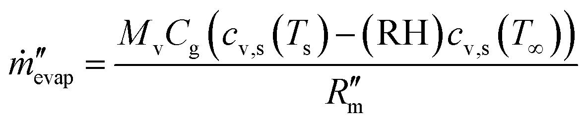
Simulations and experiments were conducted to benchmark dark evaporation rates from water-only interfaces exposed to the ambient conditions (Fig. 1a). In the simulation, we modeled natural convection coupled with evaporation from water inside an open container in contact with a large air reservoir, representing the typical experimental setups in interfacial evaporation experiments. Navier–Stokes equation for flow in water and air, energy conservation equations of water, air, and the acrylic container, and mass transfer equation of water vapor in the air are solved simultaneously in transient simulations. The boundary conditions of open boundaries, constant ambient temperature, and constant vapor concentration on the outer boundary of the air domain were imposed on the model. Constant ambient temperature was also applied at the bottom impermeable wall of the domain on which the water container and air were in contact with. Simultaneously, we also conducted experiments of water-only evaporation inside a large chamber with controlled humid air flow. During the experiment, we measured the evaporation rate from the water container as a function of ambient humidity and recessed surface height (see the experimental section for details of the simulations and experiments). | ||
Fig. 1 Flow pattern and mass transfer during dark evaporation. (a) Schematic of common experimental setup for comparative natural evaporation experiments between water-only interface and porous evaporators. (b) Predicted evaporation rates from the FEA model at different relative humidity (RH) values and container sizes. Comparisons with experiments are shown with solid diamonds. The ambient temperature is kept at 23 °C for simulations. For RH = 30%, (c) vapor density distribution is plotted along with vapor flux as white arrows and (d) temperature profile along with natural convection-induced flow velocities as white arrows. Vector arrow lengths depict magnitudes. (e) Schematic of the mass transfer resistance inside wetted pores,  , due to the meniscus relative to the mass transfer resistance from the vapor concentration boundary layer, , due to the meniscus relative to the mass transfer resistance from the vapor concentration boundary layer,  . . | ||
The results for evaporation rates from the simulations and experiments on water are presented in Fig. 1b in which good agreement is found between the simulation and experiment for different container sizes. As seen in Fig. 1b, the size of the sample strongly influences the evaporation rates. A container with a diameter of 1 cm will lead to evaporation rates 53% higher than that of a 3 cm container at 10% relative humidity. The evaporation rate decreases almost linearly with the ambient relative humidity due to the smaller vapor mole fraction difference between the surface and ambient.
The mass transfer resistance of vapor into the air across the boundary layer can be estimated from the simulations using the general mass transfer convective boundary condition
 | (1) |
 is the mass flux per unit area,
  describes the convective mass transfer resistance of water vapor through the air per unit area between the evaporating surface and the ambient, Ts is the surface temperature, T∞ is the ambient temperature, cv,s is the saturated vapor mole fraction at a given temperature, RH is the ambient relative humidity, Cg is the molar density of ambient air, and Mv is the molar mass of water. Using the simulation data, it was found that
  ranges from 114 s m−1 to 373 s m−1 for the studied different container sizes and ambient humidity values.
The thickness of the boundary layer provides a length scale that characterizes the evaporation mass transfer resistance on the air side. For example, many reported interfacial evaporators have surface areas larger than its projected surface area through either open pore structures or 3D macrostructures.28–30 If the surface structure is much smaller than the boundary layer, i.e. with micron-sized pores, then the additional surface area may not contribute to evaporation as depicted in Fig. 1e. Water vapor needs to diffuse from the enhanced surface area in the meniscus out to the far field. Although there is a larger evaporating surface area, the water vapor does not have the kinetics to escape from the micron-pores into the far-field outside of the boundary layer. This is because this diffusion resistance inside the pore meniscus is in series with the convective boundary layer resistance outside, resulting in the rate limiting step to be through the macroscopic concentration boundary layer. The mass transfer resistance inside the pore can be estimated using a simple diffusion expression
 | (2) |
 is about 0.04 s m−1, which is four orders of magnitude smaller than the boundary layer resistance as found from eqn (1). As a result, the region near the pore remains close to the saturated vapor pressure condition and it cannot explain enhanced evaporation from microporous materials. If the characteristic size of the surface roughness or macrostructures is comparable or larger than the boundary layer thickness, then the additional surface area may contribute to evaporation, as seen in open porous materials with higher evaporation rates due to forced convection or 3D evaporating macrostructures.28–30
Three effects not discussed here that could enhance evaporation kinetics of vapor transport are the transport of concentrated vapor in air, increased surface vapor mole fraction from pressurized water in hydrophobic nanopores, and enhanced transport from surface roughness. First, if the vapor concentration and flux are large enough, the vapor flux from the surface can perturb the boundary layers above the evaporating surface. One example is Stefan-flow in which vapor flux in the air side induces a Stefan velocity from counter-diffusion of air molecules near the evaporating surface.25 However, this effect is only noticeable at elevated surface temperatures (>60 °C) when the vapor mole fraction becomes comparable with that of air.31 The condition for low-rate mass transfer so that the vapor flux does not perturb the boundary layer can be described as25
 | (3) |
Water recessed height effects on natural evaporation
The above discussion of the flow pattern allows us to discern four potential pitfalls in previous dark experiments used to compare evaporation rates from water-only and from porous material surfaces (Fig. 2a–c). First, for water-only experiments, the water surface will be recessed inside the container if a beaker is used to avoid water overflowing into the pouring lip, as shown in Fig. 2a. Porous evaporators do not have this issue so they can be situated higher up inside the beaker or fixed in position due to expansion when it uptakes water, leading to experimental artifacts in relative height differences of evaporating surfaces. Secondly, since some porous evaporators are free floating on top of a water surface during experiments, the free-floating evaporator will be higher up if the same amount of water is used between tests. If the container doesn’t closely match in size with the evaporator, the sidewall can also contribute to additional evaporation as illustrated in Fig. 2b and highlighted in the past.22 Thirdly, due to the irregular shape of many porous evaporators, it has become common practice to use a cylindrical container that is larger than the sample and cover the excess water surface area with foam. The sample will be level with the foam during evaporation tests. However, the comparative water test will have a recessed level due to the thickness of the foam and artificially deflate the water evaporation rate as shown in Fig. 2c. Fourth, during longtime experiments, the water level from a free surface will drop from evaporation unless a connected reservoir is used. As a result, the apparent evaporation rate would be lower than an experiment where the height is maintained. | ||
| Fig. 2 Effects of experimental setup on apparent measured evaporation rates. (a) ṁbase is the base case rate when pure water is leveled with container lip, ṁrec is for water recessed below the lip. (b) ṁfloat,samp represents the case when the porous floating sample top surface rises above the container lip. Evaporation from the side leads to a higher apparent rate than ṁbase. (c) ṁfoam,samp is the rate when foam insulation wraps around the sample during evaporation experiments, which is lower than ṁbase as the edge effect is reduced in the former. ṁfoam,rec represents the rate with foam in the absence of sample, which is even lower due to the recessed water level. (d) Effects of recessed evaporating surface on evaporation rates from FEA simulations (blue dashed line) and experiments (blue diamonds). Simulations are conducted for 30% RH at 23 °C. Experiments are conducted in 31.1 ± 1.1% RH at 24.58 ± 0.15 °C. FEA snapshots of the vapor concentration distribution and natural convection velocity magnitudes evaporating into 30% RH and 23 °C ambient with the water surface (e) leveled with the container lip and (f) 6 mm below the container lip. Arrow lengths are normalized linearly to the largest velocity seen in both simulations. | ||
Among the above discussed scenarios, recessed water levels from the top exist in pretty much all previous experiments, and it is the most problematic because a dropped height will create a stagnant air film above the evaporating surface due to the stable density stratification, thereby decreasing the air flow velocities and the evaporation rate. Through a combination of simulations and experiments, we intentionally recessed the evaporating water surface from the container lip to quantify its effects on evaporation rates as summarized in Fig. 2d. A 2 mm recession will cause the evaporation rate to drop by 25% and a 6 mm recession will cause it to drop by 47.7% This stagnation layer can be seen clearly by comparing FEA snapshots of the natural convection flow patterns and vapor concentration gradients in Fig. 2e and f, the former with the water surface aligned with the lip of the container, while the latter with water surface recessed. As a result, water vapor molecules must first diffuse through the stagnant layer between the water surface and the lip of the container, which leads to a mass transfer resistance of about 167 s m−1 as estimated using eqn (2) with the 6 mm recessed height. This value is comparable and in series with the convective mass transfer resistance seen from earlier, causing the evaporation rate to drop by almost 50%. The coupling nature also makes the natural convective currents much weaker outside of the surface. In the comparisons between the two cases shown in Fig. 2E and F, it was found that the maximum natural convection velocity in air drops by 35% from 21.2 mm s−1 to 13.7 mm s−1. From these results, even small height differences can lead to large changes in evaporation rates.
Correlation model to study porous sample effects
To reduce the dependency on FEA simulations and provide a simplified model for researchers, we have also developed a model using heat and mass transfer correlations and used it to understand the effects of porous materials on evaporation from horizontal surfaces. Our correlation model setup has similar characteristics as Caratenuto et al.,23 but we include the physics of mass transfer and more appropriate treatment of heat transfer inside of the water to give the model predictive power of evaporation rates. The full details of the model for water-only evaporation are described in Supplementary Note S2 (see the ESI†) and the corresponding heat and mass transfer resistance diagrams are illustrated in Fig. S2 (see the ESI†).We first validated the correlation model by evaluating the evaporation of water from the water-only interface and we found good agreement in predicted evaporation rates with the simulation data as well as the experimental data (Fig. S3, see the ESI†). Using the correlation model, we can estimate the sensitivity of evaporation to different parameters to understand the effects of experimental setup (Fig. S4, see the ESI†). We set the base case as water-only inside a container with a diameter of 3 cm and height of 4 cm that is evaporating into the ambient at 30% RH and 23 °C. By testing different inputs into the model, we found that the evaporation rate is most sensitive to the ambient temperature with the evaporation rate changing by about 1.43% with every percent change in temperature in °C. This is because the ambient temperature impacts the ambient vapor content at constant RH and changes the amount of heat provided to the sample during evaporation tests. The model also shows that natural evaporation rates have reasonable sensitivity to the ambient humidity at −0.52% and diameter at −0.40%. The evaporation rate is relatively insensitive to the height (−0.002%) and thermal conductivity of the container (−0.0005%). Although the heat transfer through the sidewalls of the container could increase as the container gets taller, the mass transfer resistance of the water vapor in air cannot change significantly in natural evaporation conditions. Vapor kinetics is the rate-limiting step.
We also used the developed correlation model to test the following two hypotheses related to evaporation from porous interfacial evaporators. The first hypothesis is that a reduced latent heat causes the porous evaporator to have higher evaporation rates under natural convection, as hypothesized in many papers in the field.10,12,15–21 The second hypothesis is that a colder evaporating surface from porous materials causes faster evaporation rates.23 Using the developed model to predict evaporation from water surfaces, we extended the correlation model to describe evaporation from porous samples in natural convection conditions (Supplementary Note S3 and Fig. S5, see the ESI†).
 , is defined as
 | (4) |
 being within the 0.001 to 0.1 m2 K W−1 range.
 | ||
| Fig. 3 Dark evaporation rates and surface temperature. (a) Diagram of hypothesized water states inside of porous materials during natural evaporation experiments. An additional cooling effect must occur as bulk water enters the porous material from below if the intermediate water has lower latent heat. Differences in water enthalpies determine cooling at each of the interfaces. (b) Predicted evaporation rates as a function of relative humidity for the water-only interface (solid blue line), sample with no water latent heat changes inside (dashed gray line), and sample with water inside having half of the latent heat of bulk water (dashed dotted red line). The thermal resistance of the porous evaporator is set at 0.1 m2 K W−1, ambient temperature of 23 °C, and sample diameter of 3 cm. (c) Predicted evaporation rate, surface temperature, (d) water vapor mole fraction on the surface of the evaporator, and mass transfer coefficient in air from sample evaporation with no reduced latent heat effect as a function of the sample's thermal resistance. The ambient RH is set to 30%. | ||
We consider three cases when calculating the evaporation rates (Fig. 3b): water-only evaporation (solid blue line), sample evaporation without reduced latent heat effects (dashed gray line), and sample evaporation with reduced latent heat by half (dashed-dotted red line). Bulk water latent heat is represented by hfg. All three curves have similar features. The evaporation rate is high at low ambient humidity values and drops almost linearly as the humidity increases. More importantly, the model predicts that the evaporation rate of the water-only interface should be the highest. At 30% RH for a sample with and without reduced latent heat, the natural evaporation rates are lower than water-only by 12.4% and 3.6% respectively. This is due to the sample's thermal insulation effect, causing less heat to be transported through the bottom pathway. Since most of the heat comes through the bottom pathway, the insulating sample limits the heat transfer and causes the evaporation rate to drop.
The inclusion of intermediate water states with a reduced evaporation enthalpy of 50% increases the evaporation rate slightly when compared to sample evaporation without this effect. This is because there are less evaporative cooling effects on the air–porous evaporator interface, leading to the surface temperature and the surface vapor mole fraction to increase slightly. In addition, there must be a cooling effect at the sample–water interface due to the difference in enthalpies between bulk and intermediate water, which is commonly ignored in previous studies. This cools down the liquid water and draws additional environmental heat through the container's sidewalls. Since the total enthalpy difference needed to evaporate water depends on the initial state (bulk water) and the final state (water vapor) and all the heat ultimately comes from the ambient environment, reduced latent heat does not change the total energy needed to evaporate water beyond its effects on the surface temperature of the evaporator. Furthermore, the total heat provided from the environment to evaporation is directly proportional to the evaporation rate through the latent heat of bulk water. Fig. 3b clearly illustrates that the total heat transferred from the environment is different for the sample and for water-only evaporation due to the difference in evaporation rates, invalidating the basic assumption of comparative natural evaporation experiments that there is equal heat input.
 , and the difference in vapor mole fraction between the surface of the evaporator and in the ambient air. Although the mass transfer coefficient increases by 18.9% with decreasing temperature, the saturated surface vapor mole fraction drops by 22.4%. The change in the saturated vapor molar concentration dominates over the increasing natural convection current, leading to overall decreasing evaporation rates with colder surface temperatures.
Systematic error in the literature for natural evaporation experiments
Comparisons are now made between existing literature data and the correlation model. The experimental sample size, relative humidity, and ambient temperature from dark evaporation experiments in the literature are inputted into the correlation model. The relative differences for evaporation rates between the reported literature results and the model predictions for water-only interfaces, normalized to the model predictions, are reported in Fig. 4. The model predictions assume water surfaces are at the same level as the container lips since no experiments had reported how much water recesses below the lip during dark evaporation. Due to the variety of experimental setups used in the literature, such as open or closed environments and use of foam insulation on the surface, it cannot be expected that the literature data will match with this report's modeling exactly. However, it is still useful to compare the data to see if there are overarching trends in experiments. If evaporation rates from multiple different samples are reported in a work, we chose the sample that corresponds to the paper's reported high solar evaporation rates. | ||
| Fig. 4 Comparison with results in the literature. Relative difference of measured dark evaporation rates from water-only (blue) and samples (gray) to correlation model predictions.10,15–21,23 Sizes of samples are also displayed for clarity. Consistently lower measured evaporation from water-only surfaces suggests systematic error in previous works. | ||
For almost all studies, the evaporation rate reported for the water-only surface is systematically much lower than the predicted correlation data.10,15–21,23 Exact values for the data are shown in Table S1 (see the ESI†). The differences in evaporation rates between a container with a square cross-section vs. a circular cross-section are likely small because their characteristic sizes for external convection correlations scale similarly using the respective area to perimeter ratios.25 Since our results report evaporation rates within 10% of the model predictions for the RH conditions commonly used in experiments (30–50% RH), we believe that the predictions for dark evaporation experiments should reasonably represent the expected evaporation rates if the water is leveled to the container lips (Table S2, see the ESI†). For the porous sample data, the relative difference varies more but they are also typically lower than the model predictions as well. Some experiments in the literature were conducted in open laboratory conditions, which could have forced convective currents and make the evaporation rate higher. The relative differences are higher than what can be explained as deviations in the reported setup based on the sensitivity analysis of the correlation model. Error in the correlation model cannot explain the large discrepancies either because the correlation model generally underpredicts evaporation rates when compared to FEA simulation and experiments for samples smaller than 3 cm in diameter, suggesting that some of the findings in Fig. 4 may be an underestimate of the true relative difference. Thus, the correlation models described earlier show precisely that porous evaporators do not have higher evaporation rates than water-only surfaces due to colder surface temperatures or potential reduced latent heat effects.
The fact that most reported water-only dark evaporation rates are lower than predictions indicates that water recessing below the container’s lip is the reason. Most porous materials also have dark evaporation rates comparable to or lower than predictions, suggesting they either remain aligned or recessed below the lip level. Thus, we have strong reason to believe that larger dark evaporation rates from porous samples are not due to reduced latent heat or other porous material effects, but simply reduced dark evaporation rates from water-only surfaces due to the water level recessing below the lip.
Differential scanning calorimetry measurements
In addition to dark evaporation experiments, research groups have also used differential scanning calorimetry (DSC) measurements to validate reduced latent heat of water in interfacial solar evaporating materials. In these measurements, a temperature ramping program is used to heat small crucibles from ambient room temperature to an elevated temperature. The DSC measures the difference in heat needed to raise the temperature of a crucible with the wetted sample compared to an empty crucible with no sample. Part of the total heat flow is associated with latent heat and the other part is associated with the sensible heat, corresponding to the latent heat of evaporation and specific heat capacities respectively. However, an erroneous and common procedure is to integrate the entire heat flow curve to calculate the latent heat and the mass difference of the sample before and after the DSC measurement is used for normalization to calculate the latent heat per unit mass of water.The latent heat of evaporation is a function of both water's pressure and temperature and it can be appreciated through the Clausius–Clapeyron relationship. Many DSC experiments with porous samples will collect a significant amount of data at temperatures higher than the comparative water-only measurement.23,33–36 The porous sample temperature may even exceed 100 °C due to boiling point elevation effects, which doesn’t occur for water-only samples. The latent heat of water will decrease as the temperature increases.37,38 Furthermore, adding a non-volatile substance such as an interfacial evaporator, to form a mixture will also decrease the latent heat of evaporation due to an osmotic pressure effect on water that is dependent on its concentration.38,39 Finally, the evaporated water is estimated using the weight difference of the sample before and after the DSC experiments. There is a possibility of unaccounted water evaporation during the cooling process back to room temperature after the DSC temperature ramping program, which will also lead to a lower calculated latent heat of evaporation.
For a correct DSC measurement to be conducted for latent heat of vaporization, the equipment needs to have simultaneous thermogravimetric capabilities to measure the instantaneous mass of the wetted sample. This is because the latent heat is related to the instantaneous mass of water lost through evaporation at the current temperature and concentration during the temperature ramping program. The sensible heat is related to the amount of mass still inside of the crucible at the same time. DSCs without thermogravimetric capabilities cannot correctly deconvolute heat flow signals from the latent heat and specific heat, leading to errors in measurements.
We re-emphasize that reduced latent heat inside of the interfacial evaporator due to osmotic pressure effects does not contradict with the correlation modeling. In a continuous water evaporation process, the enthalpy difference between bulk water and intermediate water in the mixture still needs to be considered for overall energy balance to be conserved. A previous work has shown that reduced latent heat from DSC measurements do not correspond to the same increase in dark evaporation rates when compared to the water-only case,23 illustrating that transport processes such as evaporation cannot be explained from DSC measurements due to the different physics involved.
Extension of the correlation model to solar evaporation
 | ||
| Fig. 5 Behaviour under solar irradiation. Predicted correlation model (a) evaporation rates and (b) surface temperatures during solar evaporation for a porous sample with and without latent heat reduction using the correlation model. The diameter is 3 cm, thermal resistance is 0.1 m2 K W−1, and ambient temperature is 23 °C. (c) FEA simulation snapshot of the predicted temperature distributions, shown by the color gradient, for the sample's solar evaporation rates with water inside the sample having half the latent heat. The ambient humidity is set to 30% RH with the other parameters set the same in (a) and (b). (d) FEA simulated temperature distribution along the height in the center of the evaporating setup for solar evaporation with and without intermediate water states. The horizontal dotted line shows the interface between the porous sample and water and the vertical dotted line shows the ambient temperature. Note the water temperature is below the ambient with the latent heat reduction assumption and above the ambient when no latent heat reduction (also in (d)). (e) Predicted evaporation rates under forced convection conditions for porous samples with reduced latent heat using the correlation model. | ||
If the intermediate water states have reduced latent heat, a cooling effect occurs at the sample–water interface from the enthalpy difference between bulk and intermediate water. Fig. 5c illustrates the FEA steady-state temperature distribution after 2 hours of solar evaporation in simulation time. Inside of the container, the liquid water drops below the ambient temperature due to this cooling effect. When there is no reduced latent heat, the liquid water is above the ambient temperature due to heat transfer from the hot evaporating surface (Fig. S6c, see ESI†). The temperature distributions for both cases along the centerline of the container from the liquid water bottom to the top of the sample evaporating surface is plotted in Fig. 5d. For sample evaporation without reduced latent heat, the surface centerline temperature is 47.4 °C and drops to 27.4 °C at the sample–water interface. Inside the liquid water, the temperature drops almost linearly from 27.4 °C to 24.0 °C due to the stable density stratification. In contrast for sample evaporation with reduced latent heat effects, the surface centerline temperature is higher at 51.6 °C and drops to 19.3 °C at the water–sample interface. Due to the unstable density stratification, the liquid water convectively mixes and has an almost isothermal temperature profile at about 19.8 °C. The bottom of the liquid water temperature increases to 20.1 °C due to the boundary layer between the bottom container wall and the liquid water. Using the correlation model, we also studied how the water temperature changes as a function of ambient relative humidity (Fig. S6, see ESI†). For samples with and without reduced latent heat, it was predicted that the mean water temperature ranges from 16.2 to 17.9 °C and 27.2 to 28.9 °C respectively as the ambient relative humidity increases from 10 to 90%.
From these pieces of evidence, it becomes clearer how reduced latent heat from intermediate water states could impact solar evaporation rates. The vapor kinetics increase due to less evaporative cooling effects and the surface heats up. Furthermore, the liquid water drops below ambient temperature due to the large cooling effect at the sample–water interface and draws in additional heat from the environment through the container walls. However, a latent heat reduction of 50% does not increase the solar evaporation rates by a factor of 2 beyond the solar-thermal limit: the predicted evaporation rate from the correlation model at 30% RH is 1.53 kg m−2 h−1, slightly above the thermal evaporation limit of 1.49 kg m−2 h−1 if water evaporates thermally at the same surface temperature with 100% efficiency. If all locations are above the ambient temperature, the sample can only lose heat to the environment. In these cases, superthermal evaporation is impossible even with the reduced latent heat hypothesis.
 | (5) |
 | (6) |
 | (7) |
Using this correlation model, we tested to see if superthermal evaporation rates of 2 to 3 times the solar-thermal limit can be achieved using forced convection for the reduced latent heat hypothesis. The predicted evaporation rates as a function of both ambient humidity and external air velocity are illustrated in Fig. 5e. It can be seen evidently that as the external airflow increases in velocity, the evaporation rate increases as well, ranging from 1.38 to 2.05 kg m−2 h−1 as the external air velocity increases from 0.2 to 1.0 m s−1 and ambient humidity decreases from 90% to 10%. The increased evaporation rates can be attributed to lower mass transfer resistances from higher airflow velocities and higher environmental heat input into the cooled liquid water due to crossflow on the container sidewalls. The surface temperature decreases as well with increasing external airflow velocities due to larger evaporative cooling and heat loss to the environment (Fig. S8a, see the ESI†). The liquid water temperature has a more complex behavior due to competing effects between increased environmental heating from higher air flow velocities, lower heat flux from the top evaporating surface due to lower surface temperatures, and varying sample–water interface cooling effects due to the changing evaporation rates (Fig. S8b, see the ESI†). However, high superthermal evaporation rates can only be achieved if there are high airflow velocities in the lab, very dry ambient conditions, and strong cooling effects, i.e., when the liquid water and/or the surface are below the ambient temperature. The cooling effect during superthermal evaporation experiments has not been reported in the literature for 2D evaporators, leading us to conclude that the reduced latent heat model due to an intermediate water state cannot explain superthermal evaporation rates.
Potential directions for superthermal evaporation
Evidently, there is a need for both better experimental design and new directions to understand superthermal evaporation. The above discussion not only shows that the dark evaporation rates inference of reduced latent heat is prone to error, but also demonstrates that even if the hypothetically reduced latent heat was correct, it cannot lead to the doubling or tripling of the evaporation rates observed in many experiments. This is due to the limitations of vapor transport kinetics and the overall energy balance between bulk water and the vapor state. New mechanistic studies need to be rigorously conducted to understand how and why superthermal evaporation rates can occur.One potential theory that could explain this phenomenon is if water evaporates into an intermediate state, i.e. as water clusters, in the air instead of into single vapor.10,11,13 This could potentially explain superthermal evaporation rates because the enthalpy difference between bulk water and water clusters is smaller than the difference between bulk water and water vapor, allowing energy to be conserved in solar evaporation experiments while allowing evaporation rates to exceed the solar thermal limit. Furthermore, evaporation as water clusters would increase the vapor concentration at the surface of the porous evaporator, leading to enhanced mass transfer kinetics as well. However, thermal evaporation in the water cluster form is not thermodynamically favourable when compared to single molecule evaporation due to water clusters’ having larger binding energies with the evaporating surface as the cluster size increases. Future research needs to explore not only the existence of water cluster evaporation in the air during superthermal evaporation, but also the excitation mechanism for why water cluster evaporation becomes favorable.
Although Zhao et al. mentioned cluster evaporation as a possibility, they introduced the reduced latent heat mechanism, i.e., a thermal evaporation picture.10 Tu et al. showed via experiments that neither thermally heating by electrical current nor optical heating with a photothermal absorber can lead to superthermal evaporation. They then proposed and explored a hypothesis using the photomolecular effect: visible light can directly cleave off water molecular clusters through a surface interaction as a non-thermal and quantum excitation process.11 According to Maxwell's equations, the displacement field from an electric field propagating between two medium should be continuous. The large difference in the dielectric constant between air and water over the couple angstrom sized interfacial region would create a large electric field gradient. This electric field gradient can couple with the quadrupole of water clusters and excite them out of the liquid interface. Since the electric field of light is perpendicular to its direction of travel, the light needs to be polarized and strike the surface at a non-normal angle to allow a component of the electric field to interact with the air–water interface. The photomolecular effect hypothesizes that this interaction becomes more favorable in porous solar evaporators due to light trapping effects, creating many light–surface interactions to increase cluster evaporation. Tu et al. showed the wavelength dependence of superthermal evaporation and abnormal temperature profiles in the air thermal boundary layer above interfacial evaporators that could be explained using a cluster evaporation picture.11 Lv et al. conducted 14 separate experiments on a single air–water interface to further explore the photomolecular effect and cluster evaporation.13 Subsequent studies lent more support for the photomolecular picture,26,27 but significantly more work is needed to test this picture rigorously. Currently no 2D superthermal solar evaporation paper has unequivocally shown water cluster evaporation experimentally and provided a complete analysis to explain their high evaporation rate results.
Conclusions
Reduced latent heat due to intermediate states of water inside interfacial solar evaporators is a common hypothesis to explain superthermal evaporation rates. To quantify the reduced latent heat, comparison of the natural evaporation rates between a water-only surface and a porous material surface under apparent identical conditions is used to justify that water in porous materials has a reduced latent heat. The results presented above strongly indicate that such a comparison is not sound for one major reason. Dark evaporation rates from water are very sensitive to the height of the water level relative to the mouth of the container: a recessed height of a few mm can decrease the evaporation rate by about 50%. Our scaling analysis also suggests that higher natural evaporation rates from increased internal surface areas due to microporosity of 2D surface evaporators is unlikely because the dominating mass transfer resistance is in the air side boundary layer. Our analysis further shows that smaller samples are much more sensitive to external flow conditions, so very small samples of around 1 cm in size should be avoided in evaporation experiments. We advise against using these experiments to draw conclusions in changes in latent heat of water because of the sensitivity of these measurements and the lack of standardization has led to problematic conclusions on evaporation rate improvements from porous materials.Our models and simulations illustrate that the reduced latent heat hypothesis does not lead to higher natural evaporation rates, as previously assumed. What was neglected in such an argument is that when bulk water enters the porous material, a cooling effect will happen at the sample–water interface due to the difference in water enthalpy. Thus, similar amounts of heat equaling to the bulk latent heat of water must still be provided through the environment. Furthermore, for natural convection cases, the air side mass transfer resistance of water vapor cannot change significantly, leading to only small changes in predicted dark evaporation rates.
For solar evaporation, our results show that reduced latent heat leads to a small increase in evaporation rates in natural convection conditions, but never the high superthermal rates reported in the literature. With forced convection, evaporation rates could exceed the thermal limit in extremely dry ambient conditions and high convective airflows due to the lower mass transfer resistance and higher environmental heat input into the liquid water. In all cases for solar evaporation with reduced latent heat, the liquid water should achieve sub-ambient temperatures due to the large cooling effect and this effect has never been reported in the literature. In no conditions can we simulate 2–3 times evaporation rate due to latent heat reduction. We emphasize that a simple reduced latent heat picture is erroneous, which lends more credence to alternative explanations such as the photomolecular mechanism.11,13,26 Understanding the water cluster excitation process, which is statistically unfavorable in a thermal evaporation picture, is one of the biggest questions related to solar superthermal evaporation.
Experimental section
FEA simulation details
We have modeled natural evaporation in COMSOL using FEA transient simulations similar to what is conducted in laboratory experiments. We have fully simulated liquid water inside a plastic container in contact with open air using a 2D axis-symmetric setup. The container has a thickness of 2 mm, height of 4 cm, and varying diameters from 1 to 5 cm. Water convection inside the container is fully simulated. Open air is fully simulated around the container, creating a hemispherical simulation domain with a radius of 1 m. An image of the generated mesh for this domain is illustrated in Fig. S9 (see the ESI†). The general governing equations for mass, momentum, energy, and vapor transport are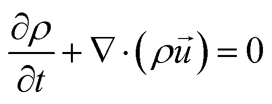 | (8) |
 | (9) |
 | (10) |
 | (11) |
The influence of setting the outer wall of the container bottom to the ambient temperature in natural convection cases is analyzed using the correlation model in Supplementary Notes S3 and S7 (ESI†). Using the correlation model, it was found that for natural evaporation of water-only interfaces, the inclusion of the effective heat transfer resistance of the scale's weighing pan changed the predicted evaporation rate by about 5% averaged across RH. This insensitivity is because (1) the heat transfer through the container sides is a parallel channel for heat transfer and is larger than the heat flux from the bottom, (2) the vapor kinetics does not change significantly during natural evaporation due to the rather small changes in surface temperature, and (3) the low evaporative cooling fluxes make the temperature difference between the water and ambient small.
At the interface between solids and fluids, the no-slip boundary condition is imposed. At the interface between the liquid and air, it is assumed that the vapor concentration is always at the saturated vapor pressure for its given temperature. Significant enhancement of the mesh is made in the region close to the evaporating surface as well as in the boundary layers due to these conditions. The initial conditions for the entire domain were set to be isothermal at the ambient temperature and the vapor pressure set at the ambient value. At the air and water interface, an additional boundary heat flux is added to include the effects of evaporative cooling and radiation exchange with the ambient air.
 | (12) |
![[r with combining right harpoon above (vector)]](https://www.rsc.org/images/entities/i_char_0072_20d1.gif) is the local coordinates in the simulation, t is the simulation time, σ is the Stefan–Boltzmann constant, and
is the local coordinates in the simulation, t is the simulation time, σ is the Stefan–Boltzmann constant, and  is the emissivity of water. As a result, the boundary heat flux is calculated locally at the air–liquid interface. The local evaporation flux,
  , comes directly from solving eqn (11) at each timestep and the local temperatures are calculated from solving the heat equations. This leads to an energy relationship between the evaporative heat flux, radiative heat transfer, and thermal conductance from the air and from the water at the interface. At steady state, these heat fluxes will balance to zero.
 | (13) |
For solar evaporation of porous samples with and without reduced latent heat effects, three additional changes are made to the simulation domain. The aluminum pan from the weighing scale is directly simulated underneath the evaporating container with the same geometric features as described in Supplementary Note S7 (see the ESI†). This feature was added to relax the bottom ambient temperature assumption from natural evaporation simulations due to the larger evaporation fluxes expected in solar evaporation. A zoomed in image of the mesh is illustrated in Fig. S11 (see the ESI†). The simulation domain of the air was also reduced to 0.6 m in radius to reduce the computation time of the simulations. Only heat conduction is assumed to happen in the porous evaporator. Since solar-thermal evaporation rates are on the order of 1 kg m−2 h−1, the net velocity of liquid water through the porous evaporator is on the order of 0.3 μm s−1, justifying the above assumption. The sample's thermophysical properties are set to 1 cm thick, a thermal conductivity of 0.1 W m−1 K−1, a specific heat capacity of 2000 J kg−1 K−1, and a density of 1200 kg m−3.
To account for solar absorption, it is assumed that the sample has 100% absorptance across the solar spectrum and has a small optical penetration depth, leading to an additional term in eqn (11) to account for 1 sun intensity  .
.
 | (14) |
 | (15) |
To include the cooling effect at the bottom interface between the solid and liquid water, the enthalpy difference is averaged over the top surface area and evenly distributed over the sample–water surface area. This calculation assumes that the cooling effect is based on the instantaneous evaporation rate at that time t. There would be a time lag between these two due to the thermal capacitance of the porous evaporator and the liquid water flowrates inside of the material. Since only steady-state results are analyzed, we expect the transient effects to not have an impact on the result. This leads to the boundary heat flux at the sample–water interface,  , to be
 | (16) |
Experimental details
All evaporation experiments are conducted in a sealed stainless-steel chamber with characteristic dimensions of 0.6 m in each axis. A schematic of the setup is illustrated in Fig. S12a (see the ESI†). An inlet allows controlled humidity air flow into the chamber at a fixed flow rate while an outlet is connected to the lab to maintain atmospheric pressure inside of the chamber. The dry air has a humidity of about 10% and its humidity is changed by flowing it through containers of saturated salt solutions. The salt solutions used are MgCl2, K2CO3, and NaCl. All water used is Type 1 Ultrapure water.For the experiments, we made a 3D printed container from polylactic acid (Fig. S12b, see the ESI†). The evaporating surface has a radius of either 0.5, 1.5, or 2.5 cm and a height of 4 cm. The connected reservoir has a radius of 3.154 cm. The reservoir is used to ensure that the evaporating height is steady during the entire experiment. The reservoir is sealed using a snap-on lid and parafilm. The top of the reservoir lid has a 0.2 mm diameter hole to maintain ambient pressure inside of the reservoir. Initially, the chamber's air is replaced with controlled humid air during an equilibration step using high flowrates for up to 3 hours. During this state, the evaporating surface is covered with a lid controlled by a stepper motor to prevent evaporation. The flow rate is then reduced to 3.5 L min−1 for at least 30 minutes before the weight loss is recorded. Once the equilibration step is completed, the stepper motor lifts the cap above the evaporating surface by 10 cm and the mass loss is recorded using a digital scale. For the 1.5 and 2.5 cm radius case, the mass loss is measured for 2 hours and only the last hour is used for data analysis. For the 0.5 cm radius case, this time is increased to 2.5 hours and lasts 1.5 hours respectively due to the smaller evaporation signal. Tests have been conducted to find that the used air flowrate has minimal impact on the measured evaporation rate (Fig. S12, ESI†). Due to the scaling relationship of eqn (7) and the sensitivity of the 1 cm evaporation rates, the flow rate during measurement is further reduced from 3.5 to 0 L min−1. The humidity and temperatures inside the chamber are constantly monitored using Honeywell HIH8000 sensors. Data collection and the stepper motors are controlled through MATLAB and Arduino setups.
Correlation model details
A correlation model is developed to describe evaporation rates from water-only and porous evaporators inside of a cylindrical container under natural convection, solar input with natural convection, and solar input with forced convection into a large ambient reservoir of air at a prescribed ambient temperature and relative humidity. The full heat and mass transfer models are described in Supplementary Notes S2–S7 (see the ESI†). All the heat and mass transfer resistances considered are inputted into a MATLAB program. Air and water's thermophysical properties are described using the film temperature between the solid interface and the bulk fluid it is in contact with. Energy conservation equations are then applied at each of the temperature nodes described in Fig. S2 and S5 (see the ESI†). The node temperatures and coefficients are iterated until a self-consistent solution is found. For natural evaporation, the vapor content effects on air's thermophysical properties are ignored due to its low concentrations. For solar evaporation calculations, the vapor content effects are incorporated when calculating air's thermophysical properties.Author contributions
J. H. Z., R. M., and G. C. developed the concept. J. H. Z. conducted the experiments. J. H. Z. prepared the models. J. H. Z., R. M., G. L., and G. C. wrote the paper. G. C. directed the overall research.Data availability
The data supporting this article and modeling methods have been included as part of the ESI.†Conflicts of interest
There are no conflicts to declare.Acknowledgements
We gratefully acknowledge funding support from the Abdul Latif Jameel Water and Food Systems Lab (J-WAFS), UM6P & MIT Research Program (UMRP), and MIT Bose Award. J. H. Z. acknowledges support from the J-WAFS Graduate Student Fellowship, the MathWorks Mechanical Engineering Fellowship, and the Harriet and Chee C. Tung Global Collaborative Fellowship. The authors would like to acknowledge Dr Wenhui Tang for her feedback on the figures and Dr Andrew Caratenuto for fruitful discussions.Notes and references
- H. J. Cho, D. J. Preston, Y. Zhu and E. N. Wang, Nat. Rev. Mater., 2016, 2, 16092 CrossRef.
- J. Chi, C. Liu, L. Che, D. Li, K. Fan, Q. Li, W. Yang, L. Dong, G. Wang and Z. L. Wang, Adv. Sci., 2022, 9, 2201586 CrossRef CAS PubMed.
- S. Zhang, X. Wei, X. Cao, M. Peng, M. Wang, L. Jiang and J. Jin, Nat. Commun., 2024, 15, 238 CrossRef CAS PubMed.
- X. Chen, M. Yang, S. Zheng, F. Temprano-Coleto, Q. Dong, G. Cheng, N. Yao, H. A. Stone, L. Hu and Z. J. Ren, Nat. Water, 2023, 1, 808–817 CrossRef CAS.
- H. Ghasemi, G. Ni, A. M. Marconnet, J. Loomis, S. Yerci, N. Miljkovic and G. Chen, Nat. Commun., 2014, 5, 4449 CrossRef CAS PubMed.
- P. Tao, G. Ni, C. Song, W. Shang, J. Wu, J. Zhu, G. Chen and T. Deng, Nat. Energy, 2018, 3, 1031–1041 CrossRef.
- C. Du, X. Zhao, X. Qian, C. Huang and R. Yang, Nano Energy, 2023, 107, 108086 CrossRef CAS.
- Z. Wang, Y. Liu, P. Tao, Q. Shen, N. Yi, F. Zhang, Q. Liu, C. Song, D. Zhang, W. Shang and T. Deng, Small, 2014, 10, 3234–3239 CrossRef CAS PubMed.
- G. Ni, S. H. Zandavi, S. M. Javid, S. V. Boriskina, T. A. Cooper and G. Chen, Energy Environ. Sci., 2018, 11, 1510–1519 RSC.
- F. Zhao, X. Zhou, Y. Shi, X. Qian, M. Alexander, X. Zhao, S. Mendez, R. Yang, L. Qu and G. Yu, Nat. Nanotechnol., 2018, 13, 489–495 CrossRef CAS PubMed.
- Y. Tu, J. Zhou, S. Lin, M. Alshrah, X. Zhao and G. Chen, Proc. Natl. Acad. Sci. U. S. A., 2023, 120, e2312751120 CrossRef CAS PubMed.
- Y. Guo, X. Zhao, F. Zhao, Z. Jiao, X. Zhou and G. Yu, Energy Environ. Sci., 2020, 13, 2087–2095 RSC.
- G. Lv, Y. Tu, J. H. Zhang and G. Chen, Proc. Natl. Acad. Sci. U. S. A., 2024, 121, e2320844121 CrossRef CAS PubMed.
- W. A. Ducker, ACS Omega, 2023, 8, 19705–19707 CrossRef CAS PubMed.
- X. Zhou, Y. Guo, F. Zhao, W. Shi and G. Yu, Adv. Mater., 2020, 32, 2007012 CrossRef PubMed.
- W. Li, X. Li, W. Chang, J. Wu, P. Liu, J. Wang, X. Yao and Z. Z. Yu, Nano Res., 2020, 13, 3048–3056 CrossRef CAS.
- H. Zou, X. Meng, X. Zhao and J. Qiu, Adv. Mater., 2023, 35, 2207262 CrossRef CAS PubMed.
- Z. Yu, R. Gu, Y. Tian, P. Xie, B. Jin and S. Cheng, Adv. Funct. Mater., 2022, 32, 2108586 CrossRef CAS.
- S. Lei, D. Huang, S. Liu, M. Chen, R. Ma, M. Zeng, D. Li, W. Ma, L. Wang and Z. Cheng, J. Mater. Chem. A, 2021, 9, 15346–15354 RSC.
- J. Chen, B. Li, G. Hu, R. Aleisa, S. Lei, F. Yang, D. Liu, F. Lyu, M. Wang, X. Ge, F. Qian, Q. Zhang and Y. Yin, Nano Lett., 2020, 20, 6051–6058 CrossRef CAS PubMed.
- Q. F. Guan, Z. M. Han, Z. C. Ling, H. Bin Yang and S. H. Yu, Nano Lett., 2020, 20, 5699–5704 CrossRef CAS PubMed.
- X. Li, G. Ni, T. Cooper, N. Xu, J. Li, L. Zhou, X. Hu, B. Zhu, P. Yao and J. Zhu, Joule, 2019, 3, 1798–1803 CrossRef.
- A. Caratenuto and Y. Zheng, Sci. Adv., 2024, 10, eadn6368 CrossRef CAS PubMed.
- B. Gebhart, Y. Jaluria, R. L. Mahajan and B. Sammakia, Buoyancy-Induced Flows and Transport, Hemisphere Publishing Corporation, New York, 1989 Search PubMed.
- J. H. Lienhard IV and J. H. Lienhard V, A Heat Transfer Textbook, Phlogiston Press, Cambridge, 5th edn, 2020 Search PubMed.
- G. Chen, Commun. Phys., 2024, 7, 330 CrossRef CAS.
- G. Verma, V. Kumar, A. Kumar and W. Li, Opt. Lett., 2024, 49, 4074 CrossRef PubMed.
- T. Gao, X. Wu, Y. Wang, G. Owens and H. Xu, Sol. RRL, 2021, 5, 2100053 CrossRef CAS.
- L. Wu, Z. Dong, Z. Cai, T. Ganapathy, N. X. Fang, C. Li, C. Yu, Y. Zhang and Y. Song, Nat. Commun., 2020, 11, 521 CrossRef CAS PubMed.
- J. Li, X. Wang, Z. Lin, N. Xu, X. Li, J. Liang, W. Zhao, R. Lin, B. Zhu, G. Liu, L. Zhou, S. Zhu and J. Zhu, Joule, 2020, 4, 928–937 CrossRef CAS.
- Z. Lu, K. L. Wilke, D. J. Preston, I. Kinefuchi, E. Chang-Davidson and E. N. Wang, Nano Lett., 2017, 17, 6217–6220 CrossRef CAS PubMed.
- D. T. Nguyen, S. Lee, K. P. Lopez, J. Lee and A. P. Straub, Sci. Adv., 2023, 9, eadg6638 CrossRef CAS PubMed.
- W. Li, X. Tian, X. Li, S. Han, C. Li, X. Z. Zhai, Y. Kang and Z. Z. Yu, J. Mater. Chem. A, 2021, 9, 14859–14867 RSC.
- Z. Y. Wang, Y. J. Zhu, Y. Q. Chen, H. P. Yu and Z. C. Xiong, Small, 2023, 19, 2206917 CrossRef CAS PubMed.
- Y. Chen, J. Yang, L. Zhu, X. Jia, S. Wang, Y. Li and H. Song, J. Mater. Chem. A, 2021, 9, 15482–15492 RSC.
- X. Suo, J. Yang, Y. Zhang, Y. Hao, J. Yang and H. Qiao, Adv. Sustainable Syst., 2021, 5, 2100122 CrossRef CAS.
- W. Wagner and A. Pruß, J. Phys. Chem. Ref. Data, 2002, 31, 387–535 CrossRef CAS.
- M. H. Sharqawy, J. H. Lienhard V and S. M. Zubair, Desalin. Water Treat., 2010, 16, 354–380 CrossRef CAS.
- G. Chen, Phys. Chem. Chem. Phys., 2022, 24, 12329–12345 RSC.
- A. Bejan, Convection Heat Transfer, John Wiley & Sons, Inc., 4th edn, 2013 Search PubMed.
Footnote |
| † Electronic supplementary information (ESI) available. See DOI: https://doi.org/10.1039/d4ee05591h |
| This journal is © The Royal Society of Chemistry 2025 |