
 Open Access Article
 This Open Access Article is licensed under a
 Creative Commons Attribution 3.0 Unported Licence
Origin of photoelectrochemical CO2 reduction on bare Cu(In,Ga)S2 (CIGS) thin films in aqueous media without co-catalysts†
Rajiv Ramanujam
Prabhakar‡
 ae,
Sudhanshu
Shukla‡
*bcd,
Haoyi
Li
ae,
R. Soyoung
Kim
e,
Wei
Chen
f,
Jérôme
Beaudelot
cg,
Jan
D’Haen
d,
Daniely Reis
Santos
bcd,
Philippe M.
Vereecken
cgh,
Gian-Marco
Rignanese
fi,
Ethan J.
Crumlin
ej,
Junko
Yano
ak,
Bart
Vermang
bcd and
Joel W.
Ager
III
*aelm
ae,
Sudhanshu
Shukla‡
*bcd,
Haoyi
Li
ae,
R. Soyoung
Kim
e,
Wei
Chen
f,
Jérôme
Beaudelot
cg,
Jan
D’Haen
d,
Daniely Reis
Santos
bcd,
Philippe M.
Vereecken
cgh,
Gian-Marco
Rignanese
fi,
Ethan J.
Crumlin
ej,
Junko
Yano
ak,
Bart
Vermang
bcd and
Joel W.
Ager
III
*aelm
aLiquid Sunlight Alliance, Lawrence Berkeley National Laboratory, Berkeley, California 94720, USA. E-mail: jwager@lbl.gov
bImec, Imo-imomec, Thor Park 8320, 3600, Genk, Belgium. E-mail: sudhanshu.shukla@imec.be
cEnergyVille, Thor Park 8320, 3600, Genk, Belgium
dHasselt University, Institute for Materials Research (imo-imomec), Analytical & Microscopical Services (AMS), Martelarenlaan 42, B-3500 Hasselt, Belgium
eChemical Sciences Division, Lawrence Berkeley National Laboratory, Berkeley, California 94720, USA
fUCLouvain, Institut de la Matière Condensée et des Nanosciences (IMCN), Louvain-la-Neuve, 1348, Belgium
gImec Leuven Kapeldreef 75, 3001, Leuven, Belgium
hKU Leuven, M2S, cMACS, Celestijnenlaan 200F, 3001, Leuven, Belgium
iWEL Research Institute, 1300 Wavre, Belgium
jAdvanced Light Source, Lawrence Berkeley National Laboratory, Berkeley, California 94720, USA
kMolecular Biophysics and Integrated Bioimaging Division, Lawrence Berkeley National Laboratory, Berkeley, California 94720, USA
lDepartment of Materials Science and Engineering, University of California, Berkeley, Berkeley, CA 94720, USA
mMaterials Sciences Division, Lawrence Berkeley National Laboratory, Berkeley, California 94720, USA
First published on 15th January 2025
Abstract
Photoelectrochemical (PEC) CO2 reduction (CO2R) on semiconductors provides a promising route to convert CO2 to fuels and chemicals. However, most semiconductors are not stable under CO2R conditions in aqueous media and require additional protection layers for long-term durability. To identify materials that would be stable and yield CO2R products in aqueous conditions, we investigated bare Cu(In,Ga)S2 (CIGS) thin films. We synthesized CIGS thin films by sulfurizing a sputtered Cu–In–Ga metal stack. The as-synthesized CIGS thin films are Cu-deficient and have a high enough bandgap (1.7 eV) suitable to perform CO2R. The bare CIGS photocathodes had faradaic yields of 14% for HCOO− and 30% for CO in 0.1 M KHCO3 electrolyte without the use of any co-catalysts under 1 sun illumination at an applied bias of −0.4 V vs. RHE and operated stably for 80 min. Operando Raman spectroscopy under CO2R conditions showed that the dominant A1 mode of CIGS was unaffected during operation. Post-mortem X-ray photoelectron spectroscopy (XPS) and X-ray absorption spectroscopy (XAS) analysis suggests that the CO2R stability could be related to self-protection caused by the in situ formation of oxides/hydroxides of Ga and In during operation. Density functional theory (DFT) calculations also reveal that Ga and In are the preferential sites for the adsorption of CO2R products, particularly HCOO−. These results show that CIGS is a promising semiconductor material for performing direct semiconductor/electrolyte reactions in aqueous media for the PEC CO2R.
Broader contextArtificial photosynthetic systems use sunlight to convert CO2 to value added products. These are photoelectrochemical (PEC) devices that rely on semiconductor–electrolyte junctions. However, very few photocathode semiconductor materials are stable and yield CO2 reduction (CO2R) products without any protection layers and/or co-catalysts in aqueous media. This severely limits the artificial photosynthesis community from investigating direct semiconductor–electrolyte reactions and exploiting the rich interface chemistry relevant to PEC CO2R. Herein, we show stable PEC CO2R operation (>1 h) on Cu(In,Ga)S2 (CIGS) based photocathodes in aqueous media without any protection layer or co-catalyst. We combined operando spectroelectrochemical measurements, advanced photoelectron spectroscopy and computational methods to investigate the underlying reasons for the catalytic activity and aqueous stability. We found that Ga and In sites provide favorable binding energy for the CO2R intermediates and the formation of oxide/hydroxide species at the surface acts as self-passivation, improving the stability in aqueous media. A stable photocathode yielding > 40% faradaic efficiency for CO2R products (14% for HCOO− and 30% for CO) without any co-catalysts in aqueous media has rarely been reported previously. These results emphasize the importance of previously unexplored surface compositions and/or specific defects in CIGS. This work guides the community to discover other semiconductors that are catalytically active and stable under aqueous PEC CO2R conditions. |
Introduction
As shown in Scheme 1, there are two main configurations in which photoelectrochemical (PEC) CO2 reduction (CO2R) on semiconductor materials can be accomplished: (1) via a direct semiconductor/electrolyte interface or (2) with a buried junction, i.e., a semiconductor with protection layers/co-catalysts. The main distinction between the two configurations is that in (1) the semiconductor absorbs light, generates an electron–hole pair and intrinsically performs catalysis, while in (2) the semiconductor is not directly involved in the catalytic reaction. While configuration (2) has been extensively investigated to accomplish PEC CO2R,1–6 very few reports exist concerning configuration (1). The major bottleneck for a direct scheme is the scarce availability of stable (corrosion resistant) light-absorbing semiconductor materials under CO2R conditions in aqueous media.7 Among very few examples, Mg-doped CuFeO2 has been reported for configuration (1).8 However, the catalytic activity was attributed to the presence of metallic Cu on the surface rather than to the semiconductor itself.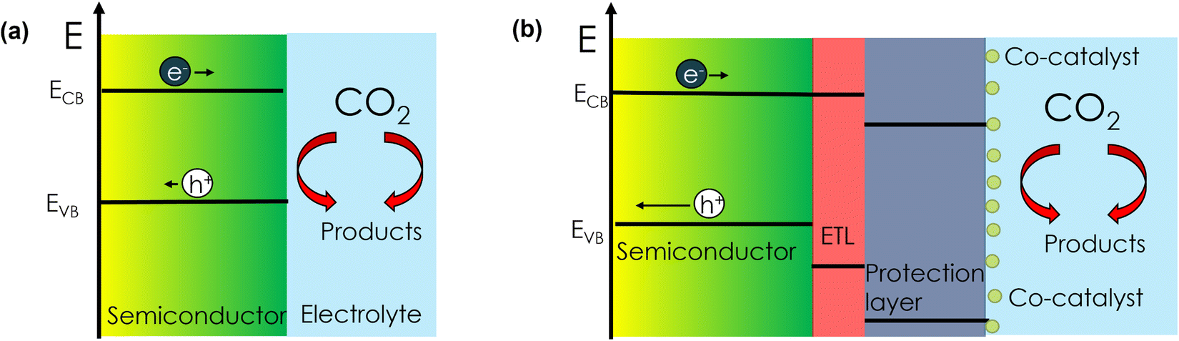 | ||
| Scheme 1 (a) Configuration (1) direct semiconductor/electrolyte for PEC CO2R. (b) Configuration (2) buried semiconductor for PEC CO2R. (Band bending is omitted for simplicity). | ||
There are reports on materials like Cu2O and Cu(In,Ga)S2 (CIGS) that do show CO2R products (CO, HCOO−), but they have been investigated in non-aqueous media due to long-term stability concerns.9,10 Chalcopyrite Cu(In,Ga)Se2 (CIGSe) with a CdS electron transport layer has been reported to be active for PEC CO2R when a molecular coating is used to limit Cd corrosion.11 However, there are no reports on using these bare materials (configuration (1)) for PEC CO2R in aqueous electrolyte. Therefore, the quest for an intrinsically stable semiconductor (that is, without protection layers or co-catalysts) that can perform PEC CO2R in aqueous media is still on.
Examination of the photocatalysis literature suggests that sulfide-based semiconductors could be promising for configuration 2. Interestingly, CuGaS2, (CuGa)0.5ZnS2, (AgInS2)x–(ZnS)2−2x, Ag2ZnGeS4, Ni- or Pb-doped ZnS, (ZnS)0.9–(CuCl)0.1, and ZnGa0.5In1.5S4 have shown promise in a particulate Z-scheme architecture with the aid of electron donors and an electron extracting layer like a reduced graphene oxide-TiO2 composite for the production of CO and HCOO−.12–14 Cu2ZnSnS4 (CZTS) has been reported to show PEC CO2R products like CO in configuration (1), but with very low photocurrents (<100 μAcm−2).15 Furthermore, Cu2ZnGeS4 (CZGS) thin films have shown CO production by PEC CO2R, but the faradaic efficiencies (FEs) were quite low (<3%).16
Cu(In,Ga)S2 (CIGS) is a non-toxic material that has been gaining attention recently for direct semiconductor/electrolyte (configuration (1)) photoelectrochemical (PEC) CO2R, with a reported FE of ∼80% for CO2R in non-aqueous electrolytes.17 However, CIGS films investigated to date under aqueous conditions have yielded very low (<4%) FE towards CO2R products like CO.9 The underlying causes of the aqueous instability and poor catalytic performance of the reported films are not clear. Recently, wide-bandgap (1.6 eV) Cu-deficient CIGS films have shown higher quasi-Fermi level splitting (qFLS) and carrier lifetime compared to stoichiometric and Cu-excess CIGS composition films, resulting in improved photovoltaic efficiencies.18,19 These considerations motivated us to investigate CIGS thin film photocathodes with even higher bandgaps (∼1.77 eV) and an intentionally highly Cu-deficient surface composition to have low intrinsic carrier losses. Moreover, a low Ga content (10–30%) in CIGS preserves the phase stability while providing a conduction band position high enough for PEC CO2R.
In this work, we show that CIGS designed following these principles is stable under PEC CO2R operation without the aid of co-catalysts or protection layers in an aqueous medium. CIGS photocathodes yielded CO2R products like CO and HCOO− with a total FE of > 40%. Using operando Raman spectroscopy, CIGS thin films were shown to be stable under PEC CO2R operation (under illumination, −0.4 V vs. RHE and 0.1 M KHCO3) as evidenced by the persistence of the A1 Raman mode for 30 min. We observed the formation of hydroxides/oxides of Ga and In after operation using X-ray photoelectron spectroscopy (XPS) and X-ray absorption spectroscopy (XAS), which suggests the presence of self-passivating layers. We further identified the Ga and In sites as being favorable for the adsorption of the CO2R reaction intermediates (COOH* and *HCOO) using density functional theory (DFT) calculations. Additionally, the Cu deficiency on the CIGS surface further enhanced intermediate binding energies. Thus, CIGS films with appropriate composition and bandgap provide a viable route for direct PEC CO2R in aqueous media.
Results and discussion
Synthesis and material characterization of CIGS thin films.
CIGS thin films were synthesized on Mo substrates by annealing a sputtered Cu–In–Ga metal stack in a H2S atmosphere (see experimental details, synthesis of CIGS thin films). We performed X-ray diffraction (XRD) and Raman spectroscopy to analyze the phase and Ga alloying. XRD reveals the highly crystalline chalcopyrite phase to be predominant in the film. All the diffraction peaks could be indexed to the tetragonal chalcopyrite structure of CIGS (space group I![[4 with combining macron]](https://www.rsc.org/images/entities/char_0034_0304.gif) 2d) along with additional minor peaks at ∼13.3° and 27.3°, which were identified as the layered NaInS2 phase (Fig. 1(a)),20 which is associated with the out-diffusion from the soda-lime glass substrate.21–24 The alloying of the CuInS2 lattice with smaller Ga atoms results in a shift of the XRD peak towards higher angles following Vegard's law. A shift of 0.4° corresponds to a [Ga/Ga + In] ratio (GGI) of ∼0.3 (Fig. S1, ESI†) close to the elemental composition determined from EDX analysis, i.e., Cu0.7In0.76Ga0.24S2 (Table S1, ESI†). A high degree of Cu-deficiency (ca. 30%) is clearly notable from composition measurement.
2d) along with additional minor peaks at ∼13.3° and 27.3°, which were identified as the layered NaInS2 phase (Fig. 1(a)),20 which is associated with the out-diffusion from the soda-lime glass substrate.21–24 The alloying of the CuInS2 lattice with smaller Ga atoms results in a shift of the XRD peak towards higher angles following Vegard's law. A shift of 0.4° corresponds to a [Ga/Ga + In] ratio (GGI) of ∼0.3 (Fig. S1, ESI†) close to the elemental composition determined from EDX analysis, i.e., Cu0.7In0.76Ga0.24S2 (Table S1, ESI†). A high degree of Cu-deficiency (ca. 30%) is clearly notable from composition measurement.
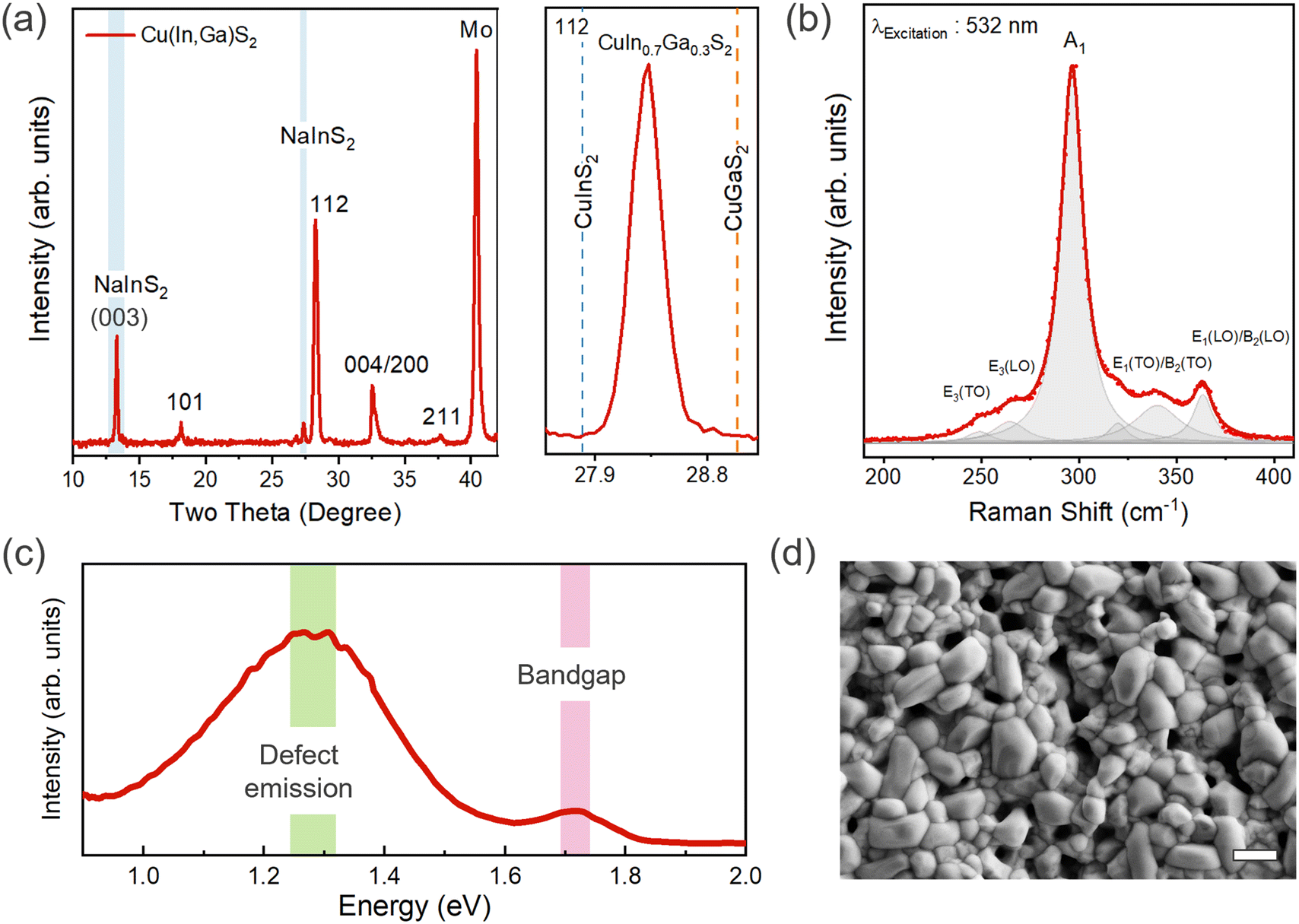 | ||
| Fig. 1 (a) XRD diffractograms and (b) Raman spectrum of the CIGS thin film, (c) PL from a wide spectral range showing a bandgap at ∼1.77 eV and broad emission at ∼1.3 eV corresponding to deep defect(s), and (d) SEM image of the CIGS thin film showing the surface morphology. Scale bar: 1 μm. | ||
We further investigated the phases present in the film using Raman spectroscopy. All Raman features are assigned to the chalcopyrite CIGS phase with no evidence of binary oxide or sulfide impurity phases. However, we note that the peak overlap between the NaInS2 and CIGS phases precludes their delineation using Raman spectroscopy.20 Fitting the Raman spectra yields the predominant A1 mode (296 cm−1) and additional modes at 250, 264, 339, and 363 cm−1 corresponding to E3(TO), E3(LO), E1(TO)/B2(TO), and E1(LO)/B2(LO) vibrational modes, respectively.25–27 For pure CuInS2 and CuGaS2, the A1 mode normally appears at 291 and 311 cm−1, respectively (Fig. 1(b)). The peak shift of 5 cm−1 compared to the pure CIS phase corresponds well to the GGI of 0.3.25 The bandgap (Eg) value of ∼1.77 eV, as determined from photoluminescence (PL) measurements, is close to the expected value of Eg for the measured [Ga]/[Ga + In] (GGI) ratio of ∼0.3 (Fig. 1(c) and Fig. S1(b), ESI†).25 We observed a broad deep defect emission below 0.5 eV from the band-edge, which has been attributed to anti-site defects (CuIn/InCu or CuGa/GaCu) in previous studies (Fig. 1(c)).19,25 The degree to which these anti-site defects are present in the film is predominantly governed by the cation ratio or the degree of copper off-stoichiometry. For instance, InCu and GaCu anti-site defects are more likely to form in a Cu-deficient film.
Examining the surface from scanning electron microscopy (SEM), we observed a coarse-grained polycrystalline film with a dense array of large and small grains having an average size of ∼1 μm (Fig. 1(d)). The sulfurization process promotes rapid grain growth governed by complex elemental interdiffusion and out-diffusion processes, while the growth kinetics determine the elemental distribution and microstructure. Consequently, voids appear at the Mo back contact due to the alkali out-diffusion process (Fig. 2(a)), with some Mo also converted to MoS2. Similar to selenide counterparts, this interfacial MoS2 (MoSe2 in the case of CIGSe) layer might be contributing to the mechanical robustness of the interface (passing the common tape peel tests) and efficient charge extraction.28,29 The thickness of CIGS is determined to be ∼1.5 μm from cross-section SEM. Atomic force microscopy (AFM) analysis further confirms the high surface roughness of the CIGS film (Fig. 2(b)), noting that high surface roughness is desirable for catalytic applications as it can provide more active sites. However, we would like to mention that the pinhole formation and high surface roughness is a characteristic feature of the two-step growth process (metal stack followed by sulfurization).30–33 In addition to well-defined CIGS grains, patches of NaInS2 phase were observed at the surface as contrast in the backscattered electron image (Fig. S2, ESI†).
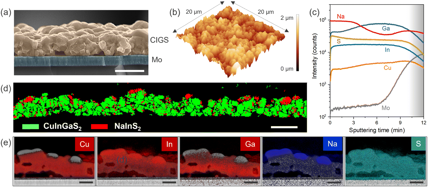 | ||
| Fig. 2 (a) Cross-section SEM micrograph, scale bar: 2 μm, (b) AFM surface morphology 3D view, and (c) elemental depth profiles (Cu, In, Ga, S, Na, and Mo) from SIMS analysis of the Mo-coated glass substrate, (d) cross-section EBSD false color plot to indicate qualitative distribution and area fraction of the CIGS (in green) and NaInS2 (in red) phase present in the sample. Scale bar: 2 μm. (e) Corresponding EDX mapping of the respective elements (Cu, In, Ga, Na, and S) showing the preferential segregation of Na at the surface. Scale bar: 1 μm. | ||
We performed secondary-ion mass spectroscopy (SIMS) analysis to probe the elemental composition as a function of depth. Fig. 2(c) shows slightly higher Ga at the Mo back contact and lower Cu at the front surface. This is consistent with the typical two-step growth processes for CIGS film preparation.30,34,35 Additionally, a higher Na level at the surface might be correlated to the NaInS2 phase previously observed in XRD. Further affirmation regarding the NaInS2 comes from the phase analysis using electron backscattered diffraction (EBSD). Fig. 2(d) shows the patches of the NaInS2 phase at the surface indicated in solid red species, while the rest of the chalcopyrite CIGS phase is shown in green. The red dots also appear in the CIGS bulk as some peak overlap occurred with the CIGS phase, sometimes causing mis-indexation (also the wrong phase and thus shown as red spots in the CIGS layer). The surface NaInS2 phase is also evident in the energy-dispersive X-ray (EDX) mapping analysis (Fig. 2(e)). Nevertheless, EBSD reveals that a significant proportion of the surface is dominated by CIGS.
PEC performance of CO2R on bare CIGS thin films in aqueous conditions
The PEC CO2R activity of bare CIGS thin films without any protection layers or co-catalysts were examined in both N2- and CO2-saturated 0.1 M KHCO3 aqueous media under 1 sun illumination by linear sweep voltammetry (LSV) (Fig. 3(a)). A higher photocurrent density from LSV in the case of CO2-saturated electrolyte confirms that the observed photocurrent from the Mo/CIGS photocathode originates from photoelectrochemical reduction of CO2. The photocurrent density typically lies within the 1.5–7 mA cm−2 range, with most around 3 mA cm−2, for CIGS-family photocathodes reported in the literature (see summary of photocurrent density in Table S2, ESI†). Therefore, the photocurrent density of 2.8 mA cm−2 observed in this study is consistent with prior reports. Note that the photocurrent density takes into account the dark current of 0.4 mA cm−2 (Fig. 3(a)). The onset potential was observed at ∼0.05 V vs. RHE, and the photocurrent density stabilized at ∼1.5 mA cm−2 with very low dark current (0.3 mA cm−2) at −0.4 V vs. RHE (Fig. 3(b)) after a rapid drop from an initial value of ∼ 3.5 mA cm−2. We attribute the photocurrent decay at the start of the measurement to the double layer charging effect resulting from the sudden change from open-circuit voltage (OCV) to an applied potential of −0.4 V vs. RHE.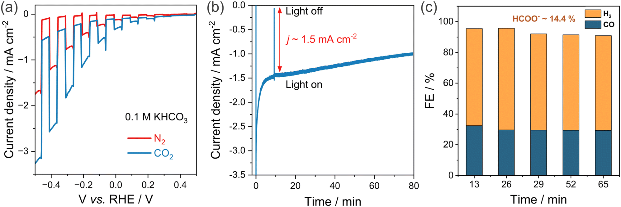 | ||
| Fig. 3 PEC testing of the bare CIGS photocathode. (a) Current density vs. potential under 1 sun chopped light measured in N2- and CO2-saturated electrolyte. (b) Current density vs. time at −0.4 V vs. RHE for CO2-saturated electrolyte. (c) Time evolution of FE for CO and H2 at −0.4 V vs. RHE. CO2 saturated 0.1M KHCO3 electrolyte, 1 sun simulated AM1.5G illumination. FE < 0.3% for gaseous products like methane and ethylene. FE < 1% for liquid products such as methanol, ethanol, and other C2+ oxygenates. | ||
The final products were individually analyzed and quantified using high precision GC and NMR measurements. A stable evolution of gaseous products (CO and H2) was observed for 80 min under 1 sun illumination at −0.4 V vs. RHE (Fig. 3(c)). Although the photocurrent density decreased slowly, the FEs for CO and H2 remained steady at around 28–32% and 60–65%, respectively. HCOO−, produced with a FE of 14%, was the sole observed liquid product, and the total FE (combining CO, H2, and HCOO−) was close to unity within experimental error. Methane and ethylene were not detected (FE < 0.3%). No liquid products (e.g. methanol, ethanol, other C2+ oxygenates) were detected by sensitive NMR measurements (FE < 1%). As discussed in the previous section, the measured photocurrent density is consistent with the reported values observed for typical wide bandgap CIGS photocathodes in the literature.17,36–40 The pinholes at the back contact might cause low photocurrents in the samples. Recent studies on high quality CuInGaS2 thin films from different synthesis routes, such as a co-evaporation process,19,41 can guide in terms of better adhesion and morphology, and consequently photocurrents can be further improved.
Origin of CIGS surface activity and degradation probed by in situ/operando Raman spectroscopy and postmortem XPS and XAS
To characterize the structural transformation of the surface during PEC operation, we utilized surface-sensitive operando Raman spectroscopy and further carried out synchrotron-based X-ray photoelectron spectroscopy (XPS) and soft X-ray absorption spectroscopy (XAS) analysis of the post-mortem CIGS. In operando Raman spectroscopy, changes in the spectral features of the characteristic vibration modes act as markers of degradation, and the evolution of peaks provides insights on the reaction mechanism.42Fig. 4 shows the Raman spectra of CIGS thin films under PEC CO2R operation (0.1 M KHCO3 at −0.4 V vs. RHE) where the Raman laser (2.33 eV) was used as the illumination source for a duration of more than 30 min starting from open-circuit voltage (OCV). No noticeable change in the spectroscopic A1 signature mode (291 cm−1) of CIGS was observed in the operando Raman spectra for the CIGS photocathodes, indicating that the photocathodes were stable under CO2R conditions. An additional peak at 350–360 cm−1 evolves as a shoulder in the Raman spectra. A signature in this spectral range is assigned to CIGS B2(LO) mode,17,25,39,43 as also evident in Fig. 1b. However, the reason behind the change in relative intensity of these modes during the measurements is not clear. The negligible changes in the microstructure of the photocathode before and after operation further corroborate the corrosion resistance of CIGS films under aqueous light-driven CO2R conditions (SEM images in Fig. S3, ESI†). In contrast, the photoelectrochemical activity of Cu0.84InGa0.26(S,Se)2 (CIGSSe) samples decreased rapidly in similar CO2R tests concomitant with the Raman peaks completely disappearing during operando measurements (Fig. S4, ESI†).
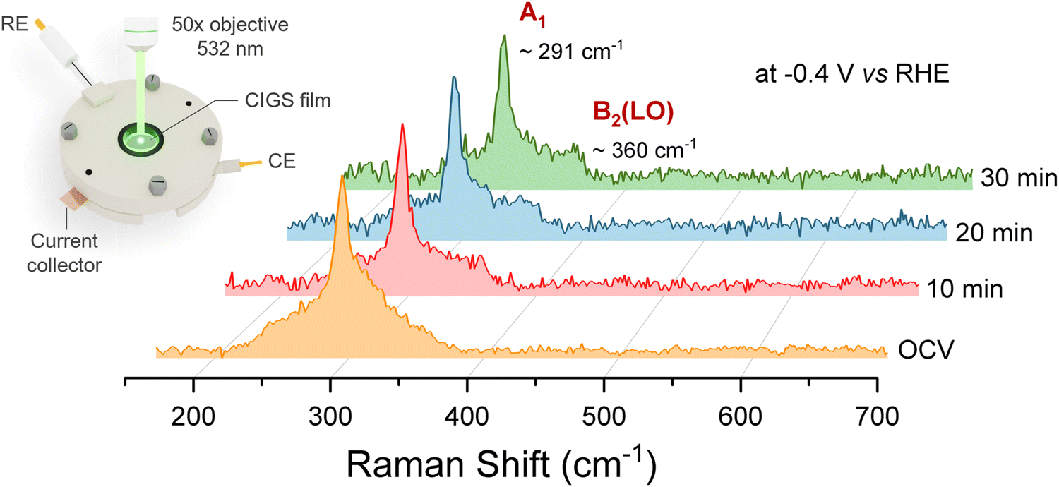 | ||
| Fig. 4 Operando Raman spectra showing the time evolution of the CIGS photocathode under CO2R operation at −0.4 V vs. RHE in CO2-saturated 0.1 M KHCO3. | ||
We conducted post-CO2R XPS measurements to elucidate the surface chemical changes and stability mechanisms in CO2R. The deconvoluted Ga 2p3/2 spectrum is depicted in Fig. 5(a). In addition to the peak corresponding to Ga–S bonding in the original CIGS,44,45 a Ga–O bonding peak (1118.5 eV) also appeared,46–48 which significantly increased after CO2R. Compared to the fresh CIGS, the Ga 3s photoelectron peak in CIGS after CO2R shifted by 0.4 eV to a higher binding energy (Fig. 5(b)), further suggesting the oxide formation during CO2R.10 Additionally, the curve fitting results of the In 3d5/2 region show the further generation of hydroxide (445.2 eV)17,18 from CO2R (Fig. 5(c)). The XPS signature of In–S bonding in CIGS overlaps with In–O bonding in In2O3 at 444.6 eV. The apparent broadening of the In–S/In–O peak after CO2R might imply the formation of oxide species. Under CO2R conditions, surface-enriched In components tended to be reduced, forming In metal, as evidenced by the emerging peak at 443.5 eV after CO2R (Fig. 5(c)).49–51 The oxides/hydroxides formation of Ga and In likely plays a crucial role in CO2R, enhancing the stability of CIGS through self-protection.52–54 Furthermore, the Cu and S 2p regions remained unchanged during electrocatalysis, implying that Ga and In serve as the catalytic active sites.
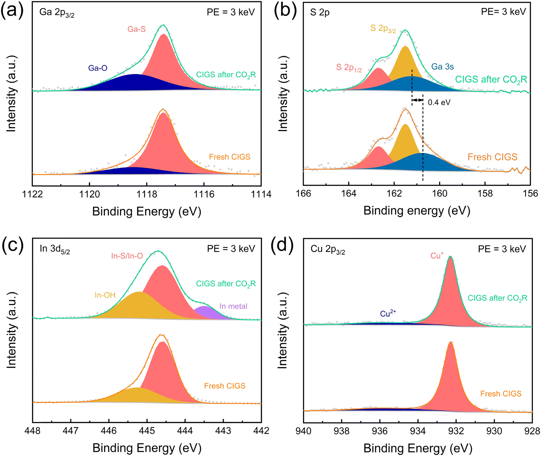 | ||
| Fig. 5 Deconvoluted XPS spectra on the CIGS before and after 80 min of CO2R operation. (a) Ga 2p3/2, (b) S 2p, (c) In 3d5/2, and (d) Cu 2p3/2 photoelectron peaks and curve fitting results (solid color area) of the fresh CIGS (bottom) and CIGS after CO2R (upper), respectively (photon energy = 3 keV). | ||
The CIGS photocathodes before and after CO2R catalysis were also examined by soft X-ray absorption spectroscopy (XAS) in the surface-sensitive total electron yield (TEY) mode. The changes in the Ga L3-edge spectrum after CO2R, compared with the spectra of Ga2S3 and Ga2O3 (Fig. S5(a), ESI†), were consistent with oxide formation as suggested by XPS. On the other hand, the In M5,4-edge spectrum of CIGS did not change much after CO2R (Fig. S5(b), ESI†), but the slight shift to lower energies is consistent with the formation of small amounts of In metal observed by XPS.
Computational studies of adsorption energies: affinity of CO2R reaction intermediates on the CIGS surface
Based on the experimental realization of CIGS photocathodes, we turned to density-functional theory (DFT) to understand the atomistic origin of CO2R on the CIGS. The PBE0 hybrid functional admixing a fraction of Fock exchange (α = 1/4) was used in the framework of the projector-augmented wave method as implemented in VASP.55–58 The long-range van der Waals interactions were included by the DFT+D3 method of Grimme et al.59 The pristine CIGS(112) surface was modeled by a six-layer CuIn0.75Ga0.25S2 slab in a tetragonal supercell comprising 192 atoms, as shown in Fig. S6 (ESI†). The In/Ga disorder is accounted for by the special quasi-random structure technique, which mimics the correlation function of a perfectly random structure.60 Specifically, the top surface layer contains six In and two Ga atoms, thereby respecting the overall stoichiometry. A vacuum of a thickness of 15 Å separates the slab from its nearest periodic image along the z direction. Upon structural relaxations, surface Ga and In atoms can undergo sizable displacement towards vacuum by 1.7 Å from their bulk positions. As a result of this outward displacement, the surface states originating from undercoordination are passivated. Hereafter, these buckled atoms are referred to as Ga* and In* to distinguish them from their counterparts that largely remain at their bulk crystalline positions. To take into account the Cu-deficient condition, a Cu vacancy is created at the surface layer, and we limit the adsorption site of the CO2R intermediates to the second-nearest neighbor to the Cu vacancy. The electrochemical conversion of CO2 to CO and formate is believed to proceed via the bound carboxylate (COOH*) and bound formate (HCOO*) intermediate, respectively.61,62 In the subsequent section, we discuss the affinity of these CO2R intermediates on the CIGS surface through free energy calculations following the computational hydrogen electrode method.63 The calculations are facilitated by workflows created with the atomate264 and jobflow65 frameworks. More computational details are described in the ESI.†The calculated Gibbs free energies of change upon adsorption (ΔG) indicate that, on both pristine and Cu-deficient surfaces, the buckled Ga* site is the primary binding site to carboxyl COOH*, the intermediate for CO2R reaction to CO, as shown in Fig. 6(a). The adsorption is mediated through the formation of the Ga*–C bond, which leads to a less prominent buckling of the Ga* atoms [cf.Fig. 6(c) and (d)]. By contrast, the ΔG is 0.6 eV higher for adsorptions on the In* site and over 2 eV higher on the Cu site. In particular, our DFT calculations show that the presence of a Cu vacancy largely stabilizes the COOH* adsorption, the effect of which is the most visible for adsorbates on the unbuckled Ga and In atoms due to their proximity to the vacancy. Nevertheless, the ΔG remains the lowest on the Ga* site, irrespective of Cu deficiency. The predominant role of the Ga* site is also confirmed for the adsorption of HCOO*, the intermediate that generally leads to the production of formate. The binding is stronger compared to the COOH* adsorption via the bridge-bonded configuration shown in Fig. 6(e).
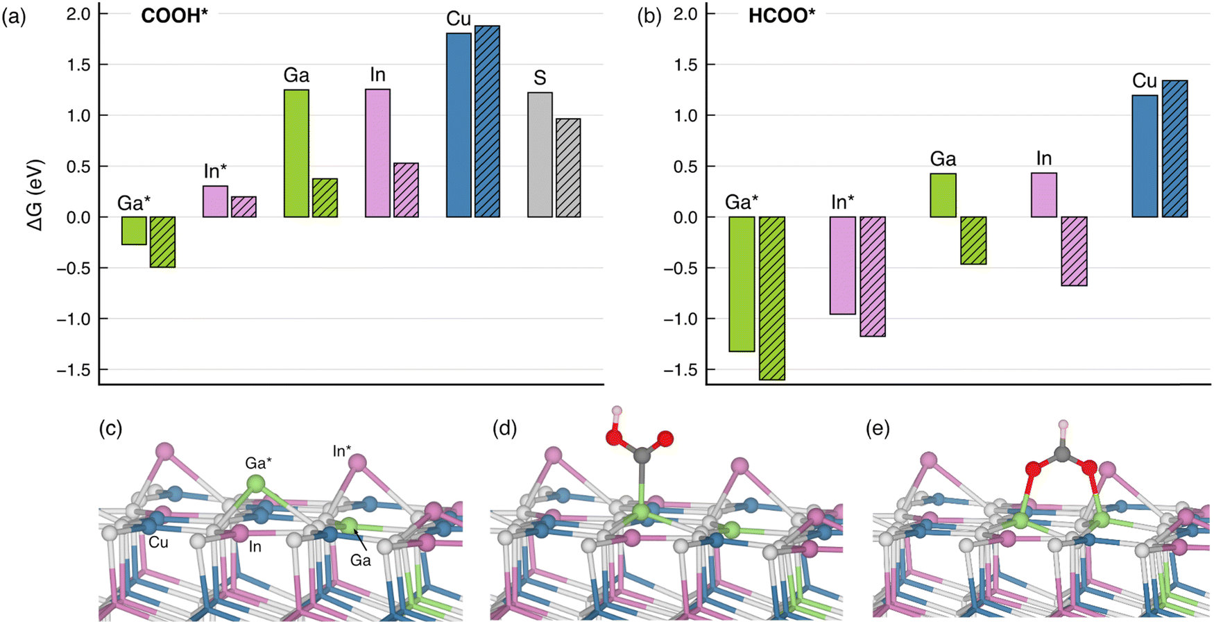 | ||
| Fig. 6 Gibbs free energy of change for the adsorption of (a) COOH* and (b) HCOO* intermediates on the pristine (solid bar) and the Cu-deficient CIGS (112) surface (shaded bar). The free energies are assessed at room temperature. The adsorption on the Cu-deficient CIGS surface occurs at the sites in the close vicinity of a surface Cu vacancy. (c) illustrates the atomic structure of the Cu-deficient CIGS (112) surface prior to adsorption. (d) and (e) correspond to the COOH* and HCOO* adsorbate structures, respectively. | ||
Overall, the ΔG values obtained with the hybrid-functional calculations corroborate the XPS and XAS assignments in that the CO2R occurs primarily through the Ga atoms and, to some extent, through the In atoms. On the other hand, we note that the enhanced catalytic activity observed under Cu-deficient conditions might correlate with the lower ΔG in the presence of a Cu vacancy, and a more rigorous account will be the subject of follow-up work. Due to the coexistence of the NaInS2, we also calculated ΔG of the two CO2R intermediates on the NaInS2 (003) surface. With ΔG as low as −3 to −5 eV (cf. Table S3, ESI†), the binding of both COOH* and HCOO* is arguably too strong to enable an effective catalytic process. Therefore, we conclude that NaInS2 is unlikely to be involved in the CO2R catalytic process.
Conclusions
In summary, we showed that CIGS could be employed as a photocathode for direct semiconductor/electrolyte CO2R in aqueous media. CIGS thin films yielded PEC CO2R products like CO and HCOO- with a combined faradaic efficiency of >40% with stability over 80 min without the need for protection layers and co-catalysts. We showed the stability of CIGS under PEC CO2R operation (−0.4 V vs. RHE and 0.1M KHCO3 under illumination) using operando Raman spectroscopy, where the main A1 mode of CIGS was unaffected. Using postmortem XPS analysis, we discovered the formation of hydroxides/oxides of In and Ga after PEC CO2R operation, which could potentially lead to self-passivation of CIGS, improving its stability. Furthermore, the calculated adsorption energies for the HCOO* and carboxyl COOH* intermediate show that the possible binding sites are Ga and In, supporting postmortem XPS and XAS analysis that they might serve as the catalytic sites. More generally, our findings suggest that the previously unexplored Cu-deficient surface composition and specific surface defects, especially deep anti-site defects, might be playing a key role in governing the unique photoelectrochemical behavior of CIGS. PEC operation on the co-catalyst free CIGS surface leads to the possibility of a simple device architecture making additional coating layers redundant. The photocurrent density and faradaic efficiency can be improved by applying a suitable electron transport layer (ETL) and co-catalyst layer. However, it is not trivial, as it is extremely challenging to steer CO2 reduction selectivity on semiconducting photocathodes, as also shown in a recent related study on Sb2Se3-based photocathodes. The bandgap tunability (variation in energy band positions) of CIGS through Ga alloying offers an advantage to further improve the PEC performance and tune the product selectivity. Looking forward, the stable performance of CIGS photocathodes for CO2 reduction in aqueous media provides a rare opportunity to understand the complex catalytic process at the semiconductor–electrolyte interface and explore the role of light itself to change the reaction kinetics at the semiconducting surface. Furthermore, the endurance of the wide bandgap CIGS films and activity towards CO2R opens a way forward towards higher order C2 products by exploiting the rich defect chemistry and promoting C–C coupling on the CIGS surface.Author contributions
Rajiv Ramanujam Prabhakar: conceptualization, methodology, validation, investigation, data curation, formal analysis, writing – original draft, writing – review & editing. Sudhanshu Shukla: conceptualization, methodology, validation, investigation, data curation, formal analysis, writing – original draft, writing – review & editing, funding acquisition. Haoyi Li: investigation, validation, data curation, formal analysis, writing – review & editing. R. Soyoung Kim: investigation, validation, data curation, formal analysis, writing – review & editing. Wei Chen: investigation, validation, data curation, formal analysis, writing – review & editing. Jérôme Beaudelot: investigation, validation, data curation, formal analysis, writing – review & editing. Jan D’Haen: investigation, validation, data curation, formal analysis, writing – review & editing. Gian-Marco Rignanese: investigation, validation, formal analysis, writing – review & editing. Ethan Crumlin: investigation, validation, formal analysis, writing – review & editing. Junko Yano: investigation, validation, formal analysis, writing – review & editing. Daniely Reis Santos: investigation, validation, formal analysis, writing – review & editing. Philippe M. Vereecken: data curation, formal analysis, writing – review & editing. Bart Vermang: conceptualization, data curation, supervision, writing – review & editing. Joel Ager: conceptualization, data curation, supervision, writing – original draft writing – review & editing, funding acquisition.Data availability
The data supporting this article have been included as part of the ESI.†Conflicts of interest
There are no conflicts to declare.Acknowledgements
This research received funding and support from the European Union's Horizon Europe program under the Marie Skłodowska-Curie Grant Agreement No. 101067667. This research is based on work performed by the Liquid Sunlight Alliance, which is supported by the U.S. Department of Energy, Office of Science, Office of Basic Energy Sciences, Fuels from Sunlight Hub under Award Number DE-SC0021266. S. S. and B. V. acknowledge Catalisti VLAIO (Vlaanderen Agentschap Innoveren & Ondernemen) through the Moonshot SYN-CAT project (HBC.2020.2614), KESPER (M-ERA.NET) and FOTON (Interreg) project. S. S., J. B. and P. M. V. acknowledge support from Belgian federal government through the Energy Transition Fund for T-REX project. D. R. S. acknowledges funds from the Fonds voor Wetenschappelijk Onderzoek – Vlaanderen (FWO) for the fellowship (No. 11PJZ24N). S. S. thanks Dr Tom Aernouts for fruitful discussions. The authors thank Dr Guy Brammertz for providing CIGSSe samples and help in SEM measurement, Tim Oris for technical support and Yesol Kim for NMR analysis. We thank Photon etc. for the hyperspectral PL measurements. The XPS and XAS studies used resources of the Advanced Light Source in Lawrence Berkeley National Laboratory, which is a DOE Office of Science User Facility under contract no. DE-AC02-05CH11231.References
- P. B. Pati, R. Wang, E. Boutin, S. Diring, S. Jobic, N. Barreau, F. Odobel and M. Robert, Nat. Commun., 2020, 11, 3499 CrossRef CAS PubMed.
- J. M. C. M. Dela Cruz, Á. Balog, P. S. Tóth, G. Bencsik, G. F. Samu and C. Janáky, EES Catal., 2024, 2, 664–674 RSC.
- J. Guerrero, E. Bajard, N. Schneider, F. Dumoulin, D. Lincot, U. Isci, M. Robert and N. Naghavi, ACS Energy Lett., 2023, 8, 3488–3493 CrossRef CAS.
- M. Xia, L. Pan, Y. Liu, J. Gao, J. Li, M. Mensi, K. Sivula, S. M. Zakeeruddin, D. Ren and M. Grätzel, J. Am. Chem. Soc., 2023, 145, 27939–27949 CrossRef CAS PubMed.
- B. Shan, S. Vanka, T.-T. Li, L. Troian-Gautier, M. K. Brennaman, Z. Mi and T. J. Meyer, Nat. Energy, 2019, 4, 290–299 CrossRef CAS.
- J. Yu, X. Hao, L. Mu, W. Shi and G. She, Chem. – Eur. J., 2024, 30, e202303552 CrossRef CAS PubMed.
- K. Wang, Y. Ma, Y. Liu, W. Qiu, Q. Wang, X. Yang, M. Liu, X. Qiu, W. Li and J. Li, Green Chem., 2021, 23, 3207–3240 RSC.
- J. Gu, A. Wuttig, J. W. Krizan, Y. Hu, Z. M. Detweiler, R. J. Cava and A. B. Bocarsly, J. Phys. Chem. C, 2013, 117, 12415–12422 CrossRef CAS.
- J. Sun, N. Guijarro, P. Li, U. Thumu, J.-H. Yum, K. Sivula and Z. M. Wang, ACS Appl. Nano Mater., 2023, 6, 10106–10114 CrossRef CAS.
- G. Liu, F. Zheng, J. Li, G. Zeng, Y. Ye, D. M. Larson, J. Yano, E. J. Crumlin, J. W. Ager, L.-W. Wang and F. M. Toma, Nat. Energy, 2021, 6, 1124–1132 CrossRef CAS.
- Y. Lai, N. B. Watkins, C. Muzzillo, M. Richter, K. Kan, L. Zhou, J. A. Haber, A. Zakutayev, J. C. Peters, T. Agapie and J. M. Gregoire, ACS Energy Lett., 2022, 7, 1195–1201 CrossRef CAS.
- S. Yoshino, A. Iwase, Y. Yamaguchi, T. M. Suzuki, T. Morikawa and A. Kudo, J. Am. Chem. Soc., 2022, 144, 2323–2332 CrossRef CAS PubMed.
- T. Takayama, K. Sato, T. Fujimura, Y. Kojima, A. Iwase and A. Kudo, Faraday Discuss., 2017, 198, 397–407 RSC.
- T. Takayama, A. Iwase and A. Kudo, ACS Appl. Mater. Interfaces, 2024, 16, 36423–36432 Search PubMed.
- T. Yoshida, A. Yamaguchi, N. Umezawa and M. Miyauchi, J. Phys. Chem. C, 2018, 122, 21695–21702 Search PubMed.
- S. Ikeda, S. Fujikawa, T. Harada, T. H. Nguyen, S. Nakanishi, T. Takayama, A. Iwase and A. Kudo, ACS Appl. Energy Mater., 2019, 2, 6911–6918 CrossRef CAS.
- Y. Liu, M. Xia, D. Ren, S. Nussbaum, J.-H. Yum, M. Grätzel, N. Guijarro and K. Sivula, ACS Energy Lett., 2023, 8, 1645–1651 CrossRef CAS PubMed.
- S. Kim, T. Nagai, H. Tampo, S. Ishizuka and H. Shibata, Prog. Photovolt.: Res. Appl., 2020, 28, 816–822 CrossRef CAS.
- S. Shukla, M. Sood, D. Adeleye, S. Peedle, G. Kusch, D. Dahliah, M. Melchiorre, G.-M. Rignanese, G. Hautier, R. Oliver and S. Siebentritt, Joule, 2021, 5, 1816–1831 CrossRef CAS.
- J. K. Larsen, K. V. Sopiha, C. Persson, C. Platzer-Björkman and M. Edoff, Adv. Sci., 2022, 9, 2200848 CrossRef CAS PubMed.
- Z.-K. Yuan, S. Chen, Y. Xie, J.-S. Park, H. Xiang, X.-G. Gong and S.-H. Wei, Adv. Energy Mater., 2016, 6, 1601191 CrossRef.
- A. Karami, M. Morawski, H. Kempa, R. Scheer and O. Cojocaru-Mirédin, Sol. RRL, 2024, 8, 2300544 CrossRef CAS.
- N. Berry, M. Cheng, C. L. Perkins, M. Limpinsel, J. C. Hemminger and M. Law, Adv. Energy Mater., 2012, 2, 1124–1135 CrossRef CAS.
- D. Rudmann, D. Brémaud, A. F. da Cunha, G. Bilger, A. Strohm, M. Kaelin, H. Zogg and A. N. Tiwari, Thin Solid Films, 2005, 480–481, 55–60 CrossRef CAS.
- S. Shukla, D. Adeleye, M. Sood, F. Ehre, A. Lomuscio, T. P. Weiss, D. Siopa, M. Melchiorre and S. Siebentritt, Phys. Rev. Mater., 2021, 5, 055403 CrossRef CAS.
- N. Guijarro, M. S. Prévot, M. Johnson, X. Yu, W. S. Bourée, X. A. Jeanbourquin, P. Bornoz, F. Le Formal and K. Sivula, J. Phys. D: Appl. Phys., 2017, 50, 044003 CrossRef.
- A. Neisser, I. Hengel, R. Klenk, T. W. Matthes, J. Álvarez-García, A. Pérez-Rodríguez, A. Romano-Rodríguez and M. C. Lux-Steiner, Sol. Energy Mater. Sol. Cells, 2001, 67, 97–104 CrossRef CAS.
- Q. Cao, O. Gunawan, M. Copel, K. B. Reuter, S. J. Chey, V. R. Deline and D. B. Mitzi, Adv. Energy Mater., 2011, 1, 845–853 CrossRef CAS.
- T. Klinkert, B. Theys, G. Patriarche, M. Jubault, F. Donsanti, J. F. Guillemoles and D. Lincot, J. Chem. Phys., 2016, 145, 154702 CrossRef CAS PubMed.
- S. Merdes, D. Abou-Ras, R. Mainz, R. Klenk, M. C. Lux-Steiner, A. Meeder, H. W. Schock and J. Klaer, Prog. Photovolt.: Res. Appl., 2013, 21, 88–93 CrossRef CAS.
- S. Merdes, R. Mainz, J. Klaer, A. Meeder, H. Rodriguez-Alvarez, H. W. Schock, M. C. Lux-Steiner and R. Klenk, Sol. Energy Mater. Sol. Cells, 2011, 95, 864–869 CrossRef CAS.
- H. Hiroi, Y. Iwata, S. Adachi, H. Sugimoto and A. Yamada, IEEE J. Photovolt., 2016, 6, 760–763 Search PubMed.
- H. Hiroi, Y. Iwata, K. Horiguchi and H. Sugimoto, IEEE J. Photovolt., 2016, 6, 309–312 Search PubMed.
- H. Hiroi, Y. Iwata, H. Sugimoto and A. Yamada, IEEE J. Photovolt., 2016, 6, 1630–1634 Search PubMed.
- G. He, C. Yan, J. Li, X. Yuan, K. Sun, J. Huang, H. Sun, M. He, Y. Zhang, J. A. Stride, M. A. Green and X. Hao, ACS Appl. Energy Mater., 2020, 3, 11974–11980 CrossRef CAS.
- H. Kaga, Y. Tsutsui, A. Nagane, A. Iwase and A. Kudo, J. Mater. Chem. A, 2015, 3, 21815–21823 RSC.
- J. J. Frick, R. J. Cava and A. B. Bocarsly, Chem. Mater., 2018, 30, 4422–4431 CrossRef CAS.
- Y. Liu, M. Bouri, L. Yao, M. Xia, M. Mensi, M. Grätzel, K. Sivula, U. Aschauer and N. Guijarro, Angew. Chem., Int. Ed., 2021, 60, 23651–23655 CrossRef CAS PubMed.
- N. Guijarro, M. S. Prévot, X. Yu, X. A. Jeanbourquin, P. Bornoz, W. Bourée, M. Johnson, F. Le Formal and K. Sivula, Adv. Energy Mater., 2016, 6, 1501949 CrossRef.
- N. Gaillard, D. Prasher, M. Chong, A. Deangelis, K. Horsley, H. A. Ishii, J. P. Bradley, J. Varley and T. Ogitsu, ACS Appl. Energy Mater., 2019, 2, 5515–5524 CrossRef CAS.
- N. Barreau, E. Bertin, A. Crossay, O. Durand, L. Arzel, S. Harel, T. Lepetit, L. Assmann, E. Gautron and D. Lincot, EPJ Photovolt., 2022, 13, 17 CrossRef CAS.
- Y. Deng and B. S. Yeo, ACS Catal., 2017, 7, 7873–7889 CrossRef CAS.
- L. Choubrac, E. Bertin, F. Pineau, L. Arzel, T. Lepetit, L. Assmann, T. Aloui, S. Harel and N. Barreau, Prog. Photovolt.: Res. Appl., 2023, 31, 971–980 Search PubMed.
- S. Yuan, X. Wang, Y. Zhao, Q. Chang, Z. Xu, J. Kong and S. Wu, ACS Appl. Energy Mater., 2020, 3, 6785–6792 CrossRef CAS.
- A. Loubat, S. Béchu, M. Bouttemy, J. Vigneron, D. Lincot, J.-F. Guillemoles and A. Etcheberry, J. Vac. Sci. Technol., A, 2019, 37, 041201 Search PubMed.
- F. Scharmann, G. Cherkashinin, V. Breternitz, C. Knedlik, G. Hartung, T. Weber and J. A. Schaefer, Surf. Interface Anal., 2004, 36, 981–985 CrossRef CAS.
- S. Béchu, M. Bouttemy, J.-F. Guillemoles and A. Etcheberry, Appl. Surf. Sci., 2022, 576, 151898 CrossRef.
- C. L. Hinkle, M. Milojevic, B. Brennan, A. M. Sonnet, F. S. Aguirre-Tostado, G. J. Hughes, E. M. Vogel and R. M. Wallace, Appl. Phys. Lett., 2009, 94, 162101 CrossRef.
- X. Yu, X. An, A. Shavel, M. Ibáñez and A. Cabot, J. Mater. Chem. A, 2014, 2, 12317–12322 RSC.
- Z. M. Detweiler, S. M. Wulfsberg, M. G. Frith, A. B. Bocarsly and S. L. Bernasek, Surf. Sci., 2016, 648, 188–195 CrossRef CAS.
- J. Li, Y. Ma, G. Chen, J. Gong, X. Wang, Y. Kong, X. Ma, K. Wang, W. Li, C. Yang and X. Xiao, Sol. RRL, 2019, 3, 1800254 CrossRef.
- F. Werner, B. Veith-Wolf, C. Spindler, M. R. Barget, F. Babbe, J. Guillot, J. Schmidt and S. Siebentritt, Phys. Rev. Appl., 2020, 13, 054004 CrossRef CAS.
- S. Garud, N. Gampa, T. G. Allen, R. Kotipalli, D. Flandre, M. Batuk, J. Hadermann, M. Meuris, J. Poortmans, A. Smets and B. Vermang, Phys. Status Solidi A, 2018, 215, 1700826 Search PubMed.
- F. Werner, B. Veith-Wolf, M. Melchiorre, F. Babbe, J. Schmidt and S. Siebentritt, Sci. Rep., 2020, 10, 7530 CrossRef CAS PubMed.
- J. P. Perdew, M. Ernzerhof and K. Burke, J. Chem. Phys., 1996, 105, 9982–9985 CrossRef CAS.
- C. Adamo and V. Barone, J. Chem. Phys., 1999, 110, 6158–6170 Search PubMed.
- G. Kresse and J. Furthmüller, Comput. Mater. Sci., 1996, 6, 15–50 Search PubMed.
- G. Kresse and J. Furthmüller, Phys. Rev. B: Condens. Matter Mater. Phys., 1996, 54, 11169–11186 CrossRef CAS PubMed.
- S. Grimme, J. Antony, S. Ehrlich and H. Krieg, J. Chem. Phys., 2010, 132, 154104 CrossRef PubMed.
- A. Zunger, S. H. Wei, L. G. Ferreira and J. E. Bernard, Phys. Rev. Lett., 1990, 65, 353–356 CrossRef CAS PubMed.
- X. Zheng, P. De Luna, F. P. García de Arquer, B. Zhang, N. Becknell, M. B. Ross, Y. Li, M. N. Banis, Y. Li, M. Liu, O. Voznyy, C. T. Dinh, T. Zhuang, P. Stadler, Y. Cui, X. Du, P. Yang and E. H. Sargent, Joule, 2017, 1, 794–805 CrossRef CAS.
- R. Kortlever, J. Shen, K. J. P. Schouten, F. Calle-Vallejo and M. T. M. Koper, J. Phys. Chem. Lett., 2015, 6, 4073–4082 CrossRef CAS PubMed.
- J. K. Nørskov, J. Rossmeisl, A. Logadottir, L. Lindqvist, J. R. Kitchin, T. Bligaard and H. Jónsson, J. Phys. Chem. B, 2004, 108, 17886–17892 CrossRef PubMed.
- atomote2: https://github.com/materialsproject/atomate2.
- A. S. Rosen, et al., Jobflow: Computational Workflows Made Simple, J. Open Source Softw., 2024, 9(93), 5995, DOI:10.21105/joss.05995.
Footnotes |
| † Electronic supplementary information (ESI) available. See DOI: https://doi.org/10.1039/d4ey00233d |
| ‡ Equal contribution. |
| This journal is © The Royal Society of Chemistry 2025 |