 Open Access Article
Multilevel azopolymer patterning from digital holographic lithography
Marcella
Salvatore
 ab,
Francesco
Reda
 a,
Fabio
Borbone
 c and
Stefano Luigi
Oscurato
 *ab
*ab
aPhysics Department “E. Pancini”, University of Naples Federico II, Complesso Universitario di Monte Sant'Angelo, via Cinthia, 80126, Naples, Italy. E-mail: stefanoluigi.oscurato@unina.it
bCentro Servizi Metrologici e tecnologici Avanzati (CeSMA), University of Naples Federico II, Complesso Universitario di San Giovanni, Corso Nicolangelo Protopisani 70, 80146, Naples, Italy
cDepartment of Chemical Sciences, University of Naples Federico II, Complesso Universitario di Monte Sant'Angelo, Via Cintia, 80126 Naples, Italy
First published on 26th November 2024
Abstract
Azopolymer-based maskless lithography enables direct, all-optical fabrication of complex surface patterns. However, typical surface reliefs are limited to smooth profiles. Here, by investigating the resolution, contrast ratio, and gray-scale nonlinearities of a holo-lithographic setup based on computer-generated holography, we extend this patterning approach to fabricate, for the first time, multilevel reliefs with step-like discontinuities.
Introduction
Photolithography has long been a fundamental technique in the field of microfabrication, facilitating substantial developments in integrated circuits, microelectromechanical systems, and photonic components.1–3 The process relies on the use of physical masks to selectively expose photoresist-coated substrates to create binary geometries with precision and reliability.4 However, traditional photolithography is limited, especially when attempting to address complex and multilevel structures. The use of photomasks increases costs and limits the versatility of the design process. Furthermore, chemical development and etching processes give rise to material waste and environmental concerns.5 To address these limitations, maskless lithography techniques have been developed, including electron beam lithography, focused ion beam lithography, and direct laser writing. These techniques enable high-resolution patterning without the need for physical masks, providing increased flexibility and eliminating the cost associated with masks.6However, these techniques predominantly yield static patterns as they still require development and etching, constraining their usefulness when reconfigurability is required.
In this context, azopolymer-based photopatterning has emerged as a promising alternative.7 Although still in the early stages of development, this approach has the potential to address the shortcomings of existing maskless methods. Azopolymers are a class of photosensitive materials embedding azobenzene molecules, which undergo reversible trans–cis photoisomerization in response to light exposure. This molecular process induces microscale mass transport,8–10 resulting in the formation of surface relief patterns without the need for chemical processing. A significant advantage of azopolymer photopatterning is the ability to dynamically monitor and adjust the formation of these patterns in real time, thereby ensuring precise control over the resulting structures.11–13 When combined with Computer-Generated Holograms (CGHs), azopolymer photopatterning stands out for its potential to dynamically generate complex structures,14–17 while maintaining the advantage of dynamic reconfigurability for the resulting surfaces.18–22 However, this technique has traditionally been used to inscribe smooth surface patterns,23–25 where the effects of resolution, contrast ratio, and possible grayscale nonlinearities were less relevant.
Here, we further extend the range of surface relief geometries on azopolymers by demonstrating controlled discrete grayscale patterns characterized by sharp intensity discontinuities, where contrast ratio and optimized resolution may be of concern. As a proof of concept, we show the direct fabrication of a multilevel surface relief with the geometry of a grayscale QR code through the optimized maskless holo-lithography system, which can potentially serve as a hyperspectral information encoder.
Materials and methods
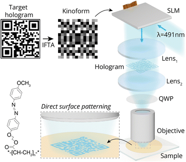
The experimental lithographic setup, schematized in Fig. 1, is based on a phase-only CGHs scheme. A coherent and collimated laser beam with linear polarization and wavelength λ = 491 nm, is phase-modulated by a reflective spatial light modulator (SLM, Pluto 2.1, Holoeye), with pixel size of Δ = 8 μm. After reflection, the beam propagates through a 4f lens system (L1 and L2) with focal lengths of f1 = 300 mm and f2 = 175 mm, respectively. These projection optics allow to generate a scaled version of the field in the SLM plane at the back focal plane of a long working distance objective. The objective has a numerical aperture of NA = 0.55 and a magnification of 50× (fobj = 4 mm). The proper SLM phase mask (kinoform) is designed using an iterative Fourier transform algorithm (IFTA),26 starting from a digital image of the target light pattern to be generated (QR code image in Fig. 1).The resulting light pattern is projected through the objective onto the free surface of the azopolymer film, producing a direct surface patterning.18,19 An average intensity of 14.0 W cm2 and circular polarization (achieved by a quarter waveplate, QWP, before the objective) are used for the azopolymer structuring in a single exposure step. A CCD camera allows to directly image the irradiated holographic pattern. To reduce the speckle noise associated to the CGH calculation, a sequence of holographic frames is used for the exposure of the polymer film, according to the procedure described previously.14 Analogously, all the experimental holographic images shown in this work are the average of 1000 independently calculated holograms. The detailed description of the optical setup is provided in our previous work.19 The azopolymer used in our experiment was synthesized by radical polymerization of (E)-2-(4-((4-methoxyphenyl) diazenyl) phenoxy) ethyl acrylate. The film was prepared by spin-coating a filtered (0.2 μm PTFE) 140 mg mL−1 solution of the polymer in 1,1,2,2-tetrachloroethane onto a glass coverslip at 300 rpm for 4 minutes, resulting in a film thickness of 1.7 μm. The chemical structure of the polymer is shown in the inset of Fig. 1. Optical and thermal properties of the material are reported in our previous works.27 Topographic characterization of the azopolymer surface reliefs was performed using an atomic force microscope (AFM) (Alpha RS300, WITec), operated in tapping mode. A cantilever with 75 kHz resonance frequency and nominal force constant of 2.8 N m−1 was used. The maximum scanned area has a size of 100 × 100 μm2.
Results and discussion
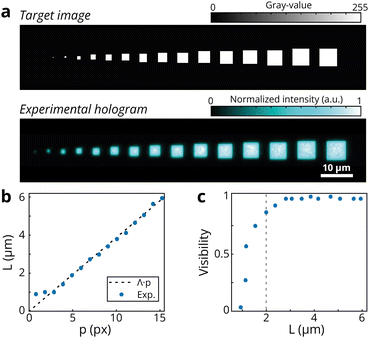
In our configuration, the SLM can be modelled as a pure phase modulator, characterized by a finite pixel pitch Δ. At the objective working distance, the complex optical field can be approximated by the Fourier transform of the modulated field at the SLM plane, with each pixel on the SLM contributing to a spatial frequency component of the reconstructed image.14,28 Each pixel of the target image is reconstructed as a diffraction-limited holographic spot.29 This spot exhibits a sinc-squared modulation in the spatial domain, arising from the Fourier transform of the square aperture of each pixel. The size δ of each holographic pixel is determined by the relation δ = 2·λ·f/Δ, where f = f1·fobj/f2 is the effective focal length of the optical system. In our setup δ ∼ 0.84 μm.28The spatial coordinates of the holographically reconstructed pattern as function of the original target image are instead determined by the angular frequencies (or Fourier components) at the SLM plane. The spacing between each physical pixel composing the holographic pattern is then Λ = (λ·f)/(N·Δ).14 Here N represents the number of illuminated SLM pixels (N = 1080 in our experiment).18 Our optical setup is designed so that the pixel spacing Λ is smaller than the pixel size δ, (Λ ∼ 0.39 μm) ensuring that the holographically reconstructed pattern appears as a continuous image. Fig. 2a summarizes the resolution calibration experiment for the experimental evaluation of both the pixel size and spacing of our holographic setup. A target image consisting of a series of squares of increasing size p (measured in pixel units) serves as the input for the holographic reconstruction. The image of the reconstructed pattern (which is the average of 1000 holographic frames) is acquired at the working distance of the objective lens, where each square corresponds to a physical size L in micrometers. The plot in Fig. 2b shows the relationship between p and L for our configuration. The dashed line represents the expected trend L = Λ·p. The experimental data closely follow this trend, deviating from the theoretical prediction as the pixel size approaches the diffraction limit δ of the system. Fig. 2c shows also the visibility of the reconstructed squares as a function of their physical size L. The visibility V is evaluated as V = (IH + IB)/(IH − IB) where IH and IB are the measured average intensity in the holographic square and in the background level, respectively. Visibility is approximately constant for L > 2 μm. On the contrary, smaller light features, closer to the diffraction limit, result in reduced visibility. Consequently, this effect will generate a reduced patterning efficiency when targeting lithographic applications with small features.
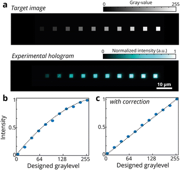
As a further step, we evaluated the capability of our system to accurately generate grayscale light levels, which are critical for lithographic applications requiring multilevel geometries. Fig. 3a shows a row of eleven target squares, each designed with linearly increasing grayscale values from 0 to 255. The corresponding experimental square holograms, with a lateral size of L = 2 μm, reveal the successful reconstruction of each square pattern, with an intensity level that reflects the intended grayscale variation. Fig. 3b provides a quantitative analysis of the optical system performance in terms of grayscale light modulation. The average intensity value in each square is plotted as a function of the designed grayscale levels. A nonlinear relationship is observed due to the inherent response characteristics of our system. This nonlinear trend, extracted from a second-order polynomial fit of the experimental data, is used as a lookup table (LUT) to be applied to the target image before the IFTA calculation process. After LUT correction, the experimental data better aligns with the target linear response, as shown in Fig. 3c, confirming that the system can faithfully reproduce linear grayscale values over the full intensity range of the target image. This result can be extended to more complex patterns with different grayscale levels, as shown in Fig. 4a.
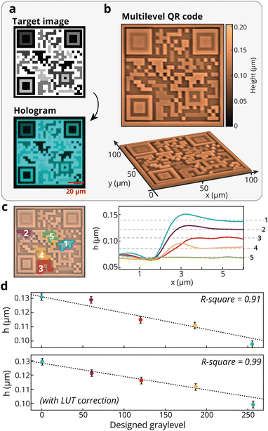
Here, the holographic pattern is designed from a QR code image by randomly varying the gray level in different regions of the image. The resulting holographic reconstruction, as seen in the experimental averaged hologram, accurately preserves both the spatial and the intensity variations of the target. By placing the azopolymer film in the holographic reconstruction plane, we transferred the grayscale modulated image onto the azopolymer surface to produce the corresponding three-dimensional surface pattern. Fig. 4b shows the AFM image of the generated multilevel QR code relief, fabricated by a 20 s exposure to the holographic pattern. Exemplifying cross-section profiles of the multilevel surface reliefs in the areas marked with different colors, corresponding to areas exposed to different illumination doses, are presented in Fig. 4c. Additionally, the plots in Fig. 4d quantify the relationship between the designed grayscale values and the resulting relief height levels h. The top plot shows the experimentally measured heights before the LUT correction. The height values are retrieved by averaging the height of the AFM image in the relative coloured zone of Fig. 4c. The LUT correction on the target image results in a reduction of nonlinear effects. As shown in the bottom plot of Fig. 4d, the experimental results closely match with the expected linear behavior, with an increase in the coefficient of determination (R-square). This demonstrates the effectiveness of the correction in compensating for the system-inherent nonlinearities, opening for the fabrication of multilevel features on the surface of azopolymer films.
Conclusions
We have demonstrated the ability to optimize a digital holographic setup for the generation of controlled discrete grayscale patterns with sharp intensity discontinuities and high contrast. The hologram was directly transferred onto an azopolymer film, demonstrating the first direct inscription of a multilevel step-like surface relief on this class of materials. The all-optical multilevel patterning demonstrated here could be further improved by accurately modelling the non-linear response of the azopolymers to the vectorial optical field, potentially achieving sharper features. Our results open for applications of azopolymer structured surfaces in new emerging fields ranging from hyperspectral data encoding and encryption to advanced optical elements manufacturing.Data availability
Data underlying the results presented in this paper are not publicly available at this time but may be obtained from the authors upon reasonable request.Author contributions
Conceptualization: M. S., F. R., S. L. O. Investigation: M. S., F. R. Methodology: M. S., F. R., F. B. Visualization: M. S., F. R. Writing – original draft: M. S. Writing – review & editing: M. S., F. R., F. B., S. L. O.Conflicts of interest
There are no conflicts to declare.Acknowledgements
This work has been financially supported by the Italian Ministry of University and Research through M4C2I1.1 funded by NexGenerationEU – PRIN PNRR 2022 program – (Grant no. P2022FKL2M), M4C2I1.5 funded by NexGenerationEU – (Grant no. ECS00000017), and by University of Naples Federico II through FRA 2022 program.References
- E. Sharma, R. Rathi, J. Misharwal, B. Sinhmar, S. Kumari, J. Dalal and A. Kumar, Nanomaterials, 2022, 12, 2754 CrossRef CAS PubMed.
- H.-C. Eckstein, U. D. Zeitner, R. Leitel, M. Stumpf, P. Schleicher, A. Bräuer and A. Tünnermann, High dynamic grayscale lithography with an LED based micro-image stepper, ed. A. Erdmann and J. Kye, San Jose, California, United States, 2016, p. 97800T Search PubMed.
- H. Wang, Y. Liu, Q. Ruan, H. Liu, R. J. H. Ng, Y. S. Tan, H. Wang, Y. Li, C. Qiu and J. K. W. Yang, Adv. Opt. Mater., 2019, 7, 1900068 CrossRef.
- Y. Wang, G. Zheng, N. Jiang, G. Ying, Y. Li, X. Cai, J. Meng, L. Mai, M. Guo, Y. S. Zhang and X. Zhang, Nat. Rev. Methods Primers, 2023, 3, 68 CrossRef CAS.
- S. Huang and K. Wu, Risk Anal., 2019, 39, 2625–2639 CrossRef PubMed.
- P. Van Assenbergh, E. Meinders, J. Geraedts and D. Dodou, Small, 2018, 14, 1703401 CrossRef PubMed.
- Z. Sekkat and S. Kawata, Laser Photonics Rev., 2014, 8, 1–26 CrossRef CAS.
- S. L. Oscurato, M. Salvatore, P. Maddalena and A. Ambrosio, Nanophotonics, 2018, 7, 1387–1422 CrossRef CAS.
- M. Saphiannikova, V. Toshchevikov and N. Tverdokhleb, Soft Matter, 2024, 20, 2688–2710 RSC.
- S. Loebner, B. Yadav, N. Lomadze, N. Tverdokhleb, H. Donner, M. Saphiannikova and S. Santer, Macromol. Mater. Eng., 2022, 307, 2100990 CrossRef CAS.
- S. L. Oscurato, F. Reda, M. Salvatore, F. Borbone, P. Maddalena and A. Ambrosio, Adv. Mater. Interfaces, 2021, 8, 2101375 CrossRef CAS.
- F. Reda, M. Salvatore, F. Borbone, P. Maddalena and S. L. Oscurato, ACS Mater. Lett., 2022, 4, 953–959 CrossRef CAS.
- H. Rekola, A. Berdin, C. Fedele, M. Virkki and A. Priimagi, Sci. Rep., 2020, 10, 19642 CrossRef CAS PubMed.
- S. L. Oscurato, M. Salvatore, F. Borbone, P. Maddalena and A. Ambrosio, Sci. Rep., 2019, 9, 6775 CrossRef PubMed.
- J. Strobelt, M. Van Soelen, H. Abourahma and D. J. McGee, Adv. Opt. Mater., 2023, 11, 2202245 CrossRef CAS.
- I. K. Januariyasa, F. Reda, F. Borbone, M. Salvatore and S. L. Oscurato, RSC Appl. Interfaces, 2024, 1, 1198–1207 RSC.
- J. Strobelt, D. Stolz, M. Leven, M. V. Soelen, L. Kurlandski, H. Abourahma and D. J. McGee, Opt. Express, 2022, 30, 7308 CrossRef CAS PubMed.
- S. L. Oscurato, F. Reda, M. Salvatore, F. Borbone, P. Maddalena and A. Ambrosio, Laser Photonics Rev., 2022, 16, 2100514 CrossRef.
- F. Reda, M. Salvatore, M. Astarita, F. Borbone and S. L. Oscurato, Adv. Opt. Mater., 2023, 11, 2300823 CrossRef CAS.
- F. Reda, M. Salvatore, F. Borbone, P. Maddalena, A. Ambrosio and S. L. Oscurato, Opt. Express, 2022, 30, 12695 CrossRef CAS PubMed.
- X. Li, H. Huang and X. Wang, Adv. Photonics Res., 2023, 4, 2200077 CrossRef CAS.
- Y. Lim, B. Kang and S. Lee, Adv. Funct. Mater., 2021, 31, 2100839 CrossRef CAS.
- M. Salvatore, F. Borbone and S. L. Oscurato, Adv. Mater. Interfaces, 2020, 7, 1902118 CrossRef CAS.
- A. Berdin, H. T. Rekola and A. Priimagi, Adv. Opt. Mater., 2024, 12, 2301597 CrossRef CAS.
- Y. Lim, B. Kang, S. J. Hong, H. Son, E. Im, J. Bang and S. Lee, Adv. Funct. Mater., 2021, 31, 2104105 CrossRef CAS.
- M. Pasienski and B. DeMarco, Opt. Express, 2008, 16, 2176 CrossRef PubMed.
- S. L. Oscurato, F. Borbone, P. Maddalena and A. Ambrosio, ACS Appl. Mater. Interfaces, 2017, 9, 30133–30142 CrossRef CAS PubMed.
- J. W. Goodman, Introduction to Fourier Optics, Macmillan Learning, Englewood, Colo, 3rd edn, 2007 Search PubMed.
- M. Agour, E. Kolenovic, C. Falldorf and C. Von Kopylow, J. Opt. A: Pure Appl. Opt., 2009, 11, 105405 CrossRef.
| This journal is © The Royal Society of Chemistry 2025 |


