Wireframe DNA origami nanostructure with the controlled opening of edges
Maryam
Mogheiseh
a and
Reza Hasanzadeh
Ghasemi
 *b
*b
aDepartment of Mechanical Engineering, Hakim Sabzevari University, Sabzevar, Iran
bDepartment of Mechanical Engineering, Hakim Sabzevari University, Sabzevar, Iran. E-mail: r.hasanzadeh@hsu.ac.ir
First published on 21st October 2024
Abstract
Wireframe DNA origami nanostructures present significant potential for a variety of applications in nanotechnology, primarily due to their straightforward design and construction processes. The precise control afforded by these nanostructures renders them exceptionally suitable for executing specific tasks. This study introduces innovative designs by altering short strands (staples) in wireframe DNA origami nanostructures, leading to different behaviors at human body temperature. These behaviors include the selective opening of certain parts of the structure while keeping other parts closed. Our research demonstrates that wireframe DNA origami nanostructures, with their numerous edges, can be engineered to allow selective opening of specific edges. This capability facilitates precise control over the structural configuration, enabling designers to customize these nanostructures to fulfill specific functional requirements. Consequently, the use of these controllable nanostructures opens up new avenues for developing nanorobots. By leveraging the unique properties of wireframe DNA origami, this study paves the way for advancements in the field of nanotechnology, particularly in the creation of versatile and adaptable nanoscale devices.
Design, System, ApplicationThis study introduces innovative designs by altering short strands (staples) in wireframe DNA origami nanostructures, leading to different behaviors. These behaviors include the selective opening of certain parts of the structure while keeping other parts closed. Our research demonstrates that wireframe DNA origami nanostructures, with their numerous edges, can be engineered to allow selective opening of specific edges. This capability facilitates precise control over the structural configuration, enabling designers to customize these nanostructures to fulfill specific functional requirements. Consequently, the use of these controllable nanostructures opens up new avenues for developing nanorobots. By leveraging the unique properties of wireframe DNA origami, this study paves the way for advancements in the field of nanotechnology, particularly in the creation of versatile and adaptable nanoscale devices. |
1. Introduction
Nanotechnology products increasingly depend on robotic devices, known as nanorobots, to perform various activities.1 Within this field, proteins and DNA serve as motors, mechanical connectors, transmission elements, or sensors.2 The unique properties of DNA make it an ideal candidate for constructing artificial nanomechanical components.3 DNA's role in nature as an information carrier further enhances its suitability for nanotechnological applications. The double-helix structure of DNA, first proposed by James Watson and Francis Crick in 1953, forms the foundation for its functionality and versatility in these roles.4In the 1980s, Seeman proposed the rational design of a Holliday junction for the first time, transforming DNA into a nanoscale polymer.5 This method allowed simple helices to extend in two dimensions, marking the beginning of DNA nanotechnology. DNA origami technology was first introduced by Rothemund in 2006 as a promising branch of DNA nanotechnology.6
DNA origami involves folding DNA to create desired two-dimensional and three-dimensional shapes at the nanoscale. This technique uses a long single-stranded DNA molecule, known as a scaffold, which is folded with the help of hundreds of shorter, designed single-stranded DNA molecules called staples.7 Since the initial demonstration of two-dimensional patterns,6 it has become possible to design nearly any desired shape, from one-dimensional to three-dimensional structures,8–10 nanopores,11,12 sensors,13 curvatures,14,15 nanotubes,16–19 joints,20,21 swingarms,22 and functional DNA origami devices.23 This method has also been employed to design DNA origami vaccines24 and drug delivery systems.25
The wireframe DNA origami method, a design technique within DNA origami technology, was first introduced by Zhang in 2015.26 This approach uses a top-down design strategy, where structures are presented as networks composed of double-stranded DNA, incorporating a custom scaffold and multiple staples. The low structural density of some wireframe designs enables their assembly under physiological ion concentrations, making them particularly suitable for biomedical applications. Additionally, this method allows the construction of larger structures from a given length of scaffold strand.27
Wireframe DNA origami geometries, compared to traditional DNA origami, DNA tile, and DNA brick methods, have the capability to form polyhedral shapes. By minimizing the use of DNA, these geometries reduce the overall scaffold length required to create two-dimensional or three-dimensional objects with specific lateral dimensions, thanks to their open and mesh-like structure.28,29
From 2016 to 2019, a team led by Bathe developed several software tools for designing two-dimensional and three-dimensional wireframe DNA origami nanostructures. These tools included DAEDALUS,30 PERDIX,31 TALOS,32 and METIS,33 which facilitated the creation of structures with edges made of either two (DX) or six (6HB) double-stranded DNA helices. In 2020, these four tools were combined into an open-source software package with a graphical user interface called ATHENA, which was further enhanced in 2021.34
Other significant contributions in the field of wireframe DNA origami include studies on nanoscale wireframe rods,35 the design of two distinct structures (compact lattice origami and non-compact wireframe origami) to evaluate DNA origami applications in biomedicine,36 and the simulation of three-dimensional wireframe DNA origami structures with 6HB edges, designed using METIS.37
The significant potential of wireframe structures in constructing nanorobot components prompted the authors to explore a design that allows for controlled usage of these structures. To create a controlled nanostructure, a deep understanding of its constituent elements is essential. Wireframe DNA origami nanostructures comprise various components, and examining their effects is crucial for designing controllable nanostructures. This paper refers to the elements of wireframe DNA origami nanostructures as “nano-components”, which include scaffold strands, staple strands, and crossovers (including scaffold crossovers and staple crossovers). Mastery over these nano-components enables precise control over wireframe DNA origami structures. In any given structure, the constituent components can significantly impact the overall stability of the construct.
The aim of this paper is to manipulate the constituent components and design wireframe DNA origami nanostructures that can open in a controlled manner. This structural modification paves the way for using wireframe structures as controllable nanostructures. The objective is to investigate the stability of wireframe DNA origami nanostructures used as controllable nanostructures from a novel perspective.
Controllable nanostructures can be created by exploring software code and modifying the design steps of wireframe DNA origami nanostructures. This paper focuses on manipulating staple strands in edges with scaffold crossovers. In recent years, there has been insufficient focus on the impact of nano-components on the applications of wireframe DNA origami nanostructures. Therefore, this study concentrates on examining the applications of wireframe DNA origami nanostructures by altering the placement of staple strands in edges with scaffold crossovers. By focusing on this aspect, the research aims to provide new insights into the functionality and potential uses of wireframe DNA origami in various nanotechnological applications.
2. Materials and methods
Scaffold routing in the design of wireframe DNA origami nanostructures is a challenging task. Therefore, new approaches have introduced a greater variety of computational tools for designing these structures. In conventional DNA origami design, caDNAno is the most widely used tool. However, for the design of wireframe DNA origami nanostructures, software such as DAEDALUS, PERDIX, TALOS, and METIS are more suitable. Modifying the nano-components of wireframe DNA origami nanostructures is one of the most exciting fields of study for examining the stability of these nanostructures, which requires proficiency in their design software. In this research, DAEDALUS software, which operates on MATLAB, is used to achieve the objectives. This research also will facilitate the manipulation and analysis of staple strands in edges with scaffold crossovers, providing new insights into the stability and functionality of wireframe DNA origami nanostructures.The design of 3D wireframe DNA origami structures in the DAEDALUS algorithm follows a top-down approach. In this software, the algorithm guides a single-stranded scaffold throughout the entire geometry and generates the necessary staple strands for folding the structure. This method ensures that the scaffold is routed efficiently and that the resulting nanostructure is stable and precisely formed.
The DAEDALUS software employs a five-step process for designing a wireframe DNA origami nanostructure. These steps include specifying geometry, generating the spanning tree, adding pseudo-nodes and scaffold routing, adding staple strands and generating sequence, and finally predicting atomic-level 3D structure.
In this research, it is focused on producing nanostructures by examining and modifying the process of adding staple strands and generating sequences using the DAEDALUS software. These nanostructures are engineered to selectively open specific edges in a controlled manner. Additionally, the coarse-grained oxDNA software was used to simulate these nanostructures under various temperature conditions.38–40 Following the simulations, the graphical user interface of oxDNA, known as oxView, was utilized to visualize the behavior of the nanoactuators.41,42
Three models of staple strands were utilized when designing wireframe DNA origami nanostructures using the DAEDALUS software, each featuring a distinct pattern. These models include staples located on vertices, staples positioned on edges with scaffold crossovers, and staples situated on edges without scaffold crossovers. This paper focuses on examining staples positioned on edges with scaffold crossovers and modifying them to design the desired nanostructures.
The placement of scaffold crossover is determined based on the edge length. In the design process of wireframe DNA origami nanostructures, facilitated by the software DAEDALUS, the scaffold crossover placement is determined during the stage of “adding staple strands and generating sequences”. The positioning of scaffold crossover depends on whether the remaining length of the edge, after adding the vertex staples to the nanostructure's edge, is a multiple of 21 or not, and whether this length is an even or odd number. The procedure is carried out as follows:
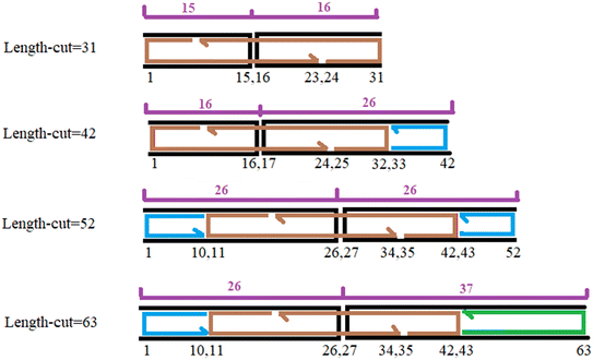
In all edges of the nanostructure, there are two types of staple strands: vertex staples and edge staples. The edge staples differ depending on whether they are located along edges with scaffold crossovers or along edges without scaffold crossovers. In each edge with scaffold crossover, the vertex staples first pair with the initial 10 or 11 nucleotides of each double-stranded DNA segment near the vertex and are connected to the vertex staple of the adjacent edge via 5-base poly-T bulges. Following this, the edge staples pair with the middle nucleotides of the edge between the vertex staples. In edges with scaffold crossover, two edge staples, each 32 or 31 nucleotides long, span the scaffold crossover, occupying a 16- or 15-nucleotide region on either side of the crossover to ensure a sufficiently strong connection.
For the remaining portion of the edge, 42-nucleotide staples are used, and if necessary, a 20- or 22-nucleotide staple is added. Edges without scaffold crossover are filled with 42-nucleotide staples as much as possible, and if required, a 20- or 22-nucleotide staple is used. It is important to note that the minimum allowable edge length in this software is 31 base pairs (bp). However, the rules explained below apply to lengths of 42 bp or more and need to be slightly modified for 31- or 32-base pair edges. A 32- or 31-bp edge consists of 21 bp occupied by vertex staples, leaving 10 or 11 bp for edge staples. Therefore, in both types of edges, a 20- or 22- bp staple with a single crossover is positioned on one side.
The placement of edge staples along edges with scaffold crossover depends on the location of the scaffold crossover, which in turn is determined by the remaining length of the edge after adding vertex staples to that edge. If, after adding vertex staples to an edge with scaffold crossover, the remaining length of the edge is a multiple of 21, the scaffold crossover will be shifted by either 5 or 5.5 nucleotides toward the lower-index vertex from the center of the edge. Specifically, if the remaining length of the edge is an even number, the scaffold crossover is shifted by 5 nucleotides; if the remaining length of the edge is odd, the scaffold crossover is shifted by 5.5 nucleotides from the center toward the lower-index vertex. Fig. 1 illustrates the placement of the scaffold crossover and edge staples for cases where the remaining length of the edge is a multiple of 21, such as 42 and 63 nucleotides, and in the case where the remaining length of the edge is not a multiple of 21, such as 31 and 52 nucleotides.
If, after adding vertex staples to an edge with scaffold crossover, the remaining length of the edge is not a multiple of 21, the scaffold crossover either remains centered or is shifted by 0.5 nucleotides toward the lower-index vertex from the center of the edge. Specifically, if the remaining length of the edge is an even number, the scaffold crossover is positioned at the center of the edge. If the remaining length is an odd number, the scaffold crossover is shifted by 0.5 nucleotides from the center toward the lower-index vertex.
In this research, a cube was designed using the DAEDALUS software. Each edge of the cube comprises 52 nucleotides and measures approximately 15 nm in length. The cube features eight vertices and 12 edges. Fig. 2a illustrates the scaffold routing within these nanostructures. In Fig. 2b, the pink lines represent the spanning tree of the nanostructure. Edges not included in the spanning tree have scaffold crossovers. Consequently, as shown in Fig. 2b, seven edges of the cube are part of the spanning tree and thus lack scaffold crossovers, whereas the remaining five edges feature scaffold crossovers. Also, Fig. 2c shows the two-dimensional spanning tree in Schlegel diagram. Fig. 2d depicts the initial structure of the cube in OxView.
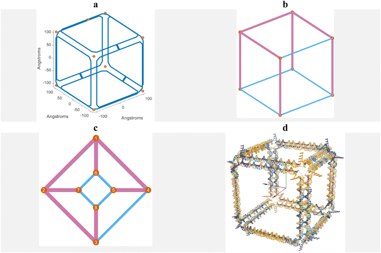 | ||
| Fig. 2 a. Scaffold routing. b. Spanning tree. c. Two-dimensional spanning tree in Schlegel diagram. d. The initial shape of the cube after being designed with the DAEDALUS software. | ||
The aim of this paper is to design and produce stable wireframe DNA origami nanostructures capable of selectively opening specific edges in a controlled manner. To achieve this, the initially stable and non-opening nano-components of the cube design, produced by the DAEDALUS software, are modified. Particularly, only edges with scaffold crossovers have the potential to open. Therefore, by altering the code of the DAEDALUS software, the placement of edge staples on edges with scaffold crossovers was modified to enable the edges to open.
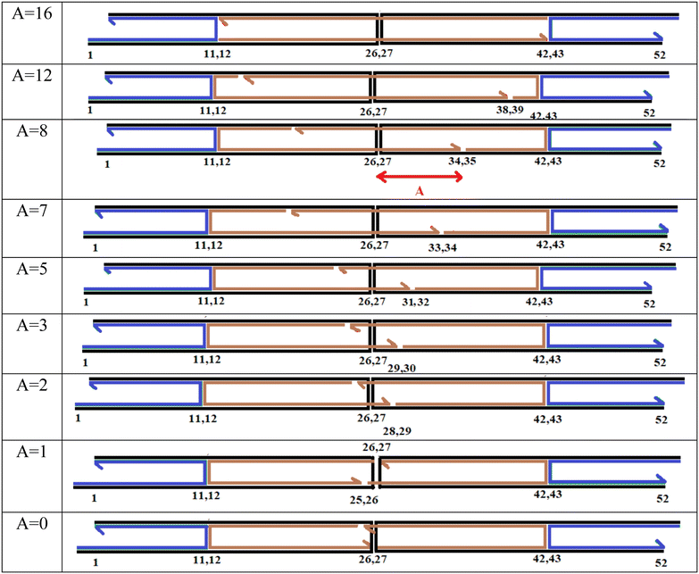
In the original DAEDALUS software code, the distance between the scaffold crossover and the end of one of the edge staples is set at 8 base pairs. The authors of this paper refer to this distance as ‘A’ and have modified it. In the original DAEDALUS code, ‘A’ is set to ensure the most reliable and stable configuration, such that the edges of the nanostructure remain closed, even at elevated temperatures. However, to achieve a structure capable of opening, the authors sought to bring the ends of the two edge staples closer to the scaffold crossover. To this end, they reduced the value of ‘A’. Of course, they are now able to adjust the distance ‘A’ in all edges with scaffold crossover, in addition to setting this distance at 0 and 8, they can now vary it within the range of 0 to 16. It should be mentioned here that 16 represents the number of base pairs are paired between the scaffold and the staple, extending from the scaffold crossover to the staple crossover. Fig. 3 illustrates the edges according to the variations in ‘A’.
Fig. 3 illustrates the design of edges with scaffold crossover in the modified version of the DAEDALUS software (note that the figures are not software outputs but are manually drawn). The rationale behind selecting these specific values for ‘A’ is also worth explaining. Values greater than 8 were chosen to allow for the assessment of stability under these conditions. Specifically, at A = 16, as shown in Fig. 3, each edge with a scaffold crossover features two staple single crossovers instead of two staple double crossovers. However, the simulation results for A = 16, presented in Fig. 5, indicate that changing the staple crossover has no significant effect on the opening of edges with scaffold crossover.
For ‘A’ values between 0 and 8, five different nanostructures with varying ‘A’ values were designed. As can be seen in the last two rows of Fig. 3, when A = 1, the number of base pairs are paired at the scaffold crossover site is similar to when A = 0. To verify this, the edge structures were thoroughly examined in oxView, with a focus on the nucleotides near the scaffold crossover, and it was clearly observed that the A = 1 case is indeed similar to A = 0. For this reason, only one of these two conditions needs to be simulated.
In this context, ‘A’ represents the number of scaffold bases (black strand) that interact with the terminal bases of an edge staple strand (brown strands). A smaller ‘A’ indicates fewer base pairs are formed, resulting in a shorter length of the edge staple strand extending through the scaffold crossover at the targeted edge. Consequently, the end of the edge staple strand is situated closer to the scaffold crossover, reducing the number of scaffold strand bases that pair with the terminal bases of the edge staple strand beyond the crossover, thus weakening the edge. Each edge in the desired structure incorporates two edge staples, so ‘A’ can be specified twice in each row of Fig. 3. To maintain clarity, however, only one instance of ‘A’ is shown for the case where A = 8.
In each row of Fig. 3, an edge with a scaffold crossover is displayed, consisting of a scaffold strand in black, vertex staples in blue, and edge staples in brown. According to the DAEDALUS software, each edge includes two double-stranded DNA. In Fig. 3, each horizontal black line represents one strand of DNA, and each horizontal colored line (blue or brown) represents the complementary strand of the double-stranded DNA. The vertical black lines denote scaffold crossover, while the vertical colored lines indicate staple crossovers. Each edge is 52 nucleotides long. Based on the descriptions in Fig. 1, each edge with a scaffold crossover includes two vertex staples and two edge staples. The first 21 nucleotides of each edge, near the vertices, pair with the vertex staples, and the remaining 31 nucleotides pair with the edge staples. Each vertex staple is 21 nucleotides long, and each edge staple is 31 nucleotides long.43
2.1. Coarse-grained computer simulations using oxDNA
Molecular dynamics (MD) simulations were conducted using the oxDNA2 model and oxDNA simulation software (version 3) to simulate the designed nanostructures and demonstrate the controlled opening capability of edges with scaffold crossovers. In contrast to all-atom MD simulations, oxDNA provides a coarse-grained approximation that enables the investigation of the thermodynamic and mechanical properties of DNA over extended time scales.40,44 Initially, the CNDO files generated by the DAEDALUS software were converted into the oxDNA file format using tacoxDNA.45The energy of all wireframe DNA origami nanostructures was minimized at a salt concentration of 1 molar [Na+]. Initial energy minimization was conducted at a temperature of 300 Kelvin over a period of 151.55 picoseconds, corresponding to 10![[thin space (1/6-em)]](https://www.rsc.org/images/entities/char_2009.gif) 000 steps with a time interval of 0.005, where each time unit represents 3.031 picoseconds. Following this, relaxation simulations were performed in a 1 molar salt concentration [Na+] and at a temperature of 300 Kelvin. These simulations included 107 steps with a time interval of 0.001, resulting in a total simulation time of 30.31 nanoseconds, with each time unit equivalent to 3.031 picoseconds. The simulations were performed using the Langevin thermostat with a diffusion coefficient of 0.5.
000 steps with a time interval of 0.005, where each time unit represents 3.031 picoseconds. Following this, relaxation simulations were performed in a 1 molar salt concentration [Na+] and at a temperature of 300 Kelvin. These simulations included 107 steps with a time interval of 0.001, resulting in a total simulation time of 30.31 nanoseconds, with each time unit equivalent to 3.031 picoseconds. The simulations were performed using the Langevin thermostat with a diffusion coefficient of 0.5.
Finally, MD simulations were carried out at a salt concentration of 1 molar [Na+] over a simulation time of 60.62 nanoseconds. These simulations consisted of 2 × 10⁷ steps with a time interval of 0.001, where each time unit is 3.031 picoseconds. The MD simulations were conducted using the john thermostat (diffusion coefficient 2.5) at a temperature of 310 Kelvin for each nanostructure.
3. Results and discussion
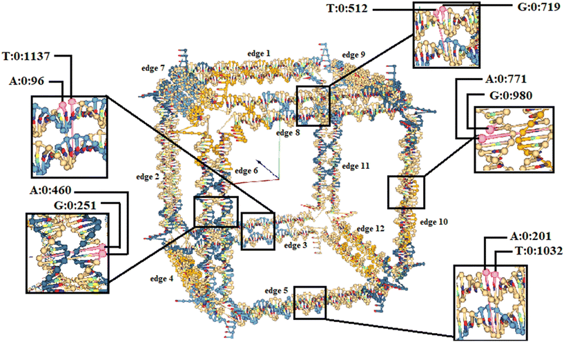
To precisely investigate the opening capability of edges with scaffold crossovers in wireframe DNA origami nanostructures, two bases located on the scaffold exactly at the crossover were selected from each edge with a scaffold crossover. The distance between these bases was measured throughout the simulation. Detailed procedures for examining the cube are elaborated on in the following sections.In the selected cube, edges numbered one, two, four, seven, nine, eleven, and twelve do not have scaffold crossover. On the other hand, edges numbered three, five, six, eight, and ten include scaffold crossover. This numbering is based on the scaffold routing (Fig. 2a). The specific bases selected for each edge with a scaffold crossover are as follows:
• For edge number three: base number 96 (adenine) and base number 1137 (thymine)
• For edge number five: base number 201 (adenine) and base number 1032 (thymine)
• For edge number six: base number 251 (guanine) and base number 460 (adenine)
• For edge number eight: base number 512 (thymine) and base number 719 (guanine)
• For edge number ten: base number 771 (adenine) and base number 980 (guanine)
Fig. 4 provides a detailed overview of the selected cube and the specified bases. For example, A:0:96 represents base number 96 selected from strand number 0, which is a adenine. The scaffold strand with index 0 is displayed in oxView and the numbering of staple strands starts from number one.
To further investigate the stability of wireframe DNA origami nanostructures with different values of ‘A’, simulations of all these nanostructures were conducted, as described in section 2.1 of the paper. In these nanostructures, the value of ‘A’ was modified across all edges with scaffold crossover. For example, when A = 3 was chosen, this value was applied to all edges with scaffold crossover. Since the aim of this study is to assess the overall stability of the structure and select the appropriate ‘A’ value to facilitate the rapid opening of edges, no specific edge was targeted for applying a particular ‘A’ value.
According to Fig. 5, when ‘A’ is varied from 3 to 16, the nanostructure remains stable after 60.62 ns of simulation, with no edges opening. However, when ‘A’ is decreased from 3 to 2, two edges with scaffold crossover begin to open during this simulation period. This indicates that if the simulation time were increased, three additional edges with scaffold crossover would also open, which would require extending the simulation duration—something that the authors of the paper do not desire.
 | ||
| Fig. 5 The final structure and the distance diagram between scaffold double crossovers on edges with scaffold crossover for different A's. | ||
A notable observation in Fig. 5 for A = 2 is that the first edge (regardless of its number) opened at approximately in 40 ns, while for A = 0 shows that five edges with scaffold crossover opened in less than 20 ns. Given that the authors seek rapid opening of the selected edges, ‘A’ was set to 0 for the simulations of the selected edges.
According to Fig. 5, to achieve wireframe DNA origami nanostructures with opening capabilities, A = 0 is assigned to edges with scaffold crossover that are intended to open during the simulation. In contrast, for edges with scaffold crossover that are not intended to open, ‘A’ is set to 8, thereby preventing them from opening.
Now, in order to investigate the unfolding of the nanostructure using selected edges, this cube has been designed and simulated in 9 different scenarios. Since 5 edges of this nanostructure have the capability to open, the number or the specific edges that open change in each scenario. To examine the opening capability, all nanostructures were simulated at a temperature of 310 Kelvin for 60.62 nanoseconds, during which the edges have the capability to open, begin to open.
The first simulation is for the scenario where the value of ‘A’ is set to 8 for all 5 edges with scaffold crossovers in the nanostructure. Therefore, in this case, these 5 edges, numbered three, five, six, eight, and ten, should maintain their stability and not open during the simulation. The third row of Fig. 5 shows the cubic nanostructure and the distances graph of the selected bases for this scenario after the coarse-grained simulation. As can be seen from the third row of Fig. 5, none of the edges with scaffold crossovers have opened, and they have maintained their stability throughout the simulation.
The next simulation considers the scenario where ‘A’ is set to 0 for one of the 5 edges capable of opening, while ‘A’ is set to 8 for the remaining edges. This configuration allows one edge to open during the simulation, while the other four edges should remain closed. Since any of the edges numbered three, five, six, eight, and ten can potentially open, we can select one of them, modify the DAEDALUS software code to specify it as the opening edge, and ensure the other four edges do not open. In this simulation, edge number three was chosen as the opening edge, and ‘A’ was set to 0 for it. Fig. 6 shows the cubic nanostructure and the distances graph of the selected bases for this scenario after the coarse-grained simulation. As illustrated in Fig. 6, one of the 12 edges of the cube has opened. The distance between bases 96 and 1137, which belong to edge number three, begins to increase after some time from the start of the simulation. Meanwhile, the distances between the selected bases for the other four edges, which have the potential to open but are not allowed to, do not increase, and these edges remain closed throughout the simulation.
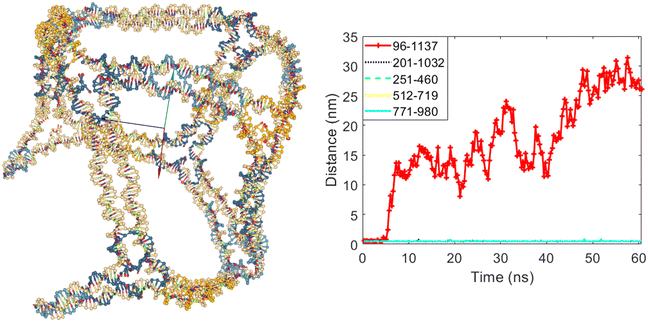 | ||
| Fig. 6 The final structure and the distances graph between bases on edges with scaffold crossover after simulation for the case where edge number three is allowed to open. | ||
The next step is to allow two of the five edges with the potential to open to actually open. By selecting the numbers of two edges in the modified DAEDALUS software code and setting ‘A’ to 0 for them, these two chosen edges are permitted to open when simulated under the specified conditions. For the remaining three edges, which also have the potential to open but have ‘A’ set to 8, they will remain closed.
To demonstrate the ability to select edge numbers in the modified DAEDALUS software code, four different cases were simulated, as shown in Fig. 7–10. For the first case, edges numbered three and six were allowed to open, while edges five, eight, and ten were set to remain closed. Fig. 7 shows the cubic nanostructure and the distances graph of the selected bases for this scenario after the coarse-grained simulation. As illustrated, two of the twelve edges of the cube have opened. According to the graph in Fig. 7, the distances between bases 96 and 1137 (belonging to edge number three) and bases 251 and 460 (belonging to edge number six) increased after the start of the simulation. In contrast, the distances between the bases of edges five, eight, and ten did not increase, confirming that these three edges remained closed despite having the potential to open.
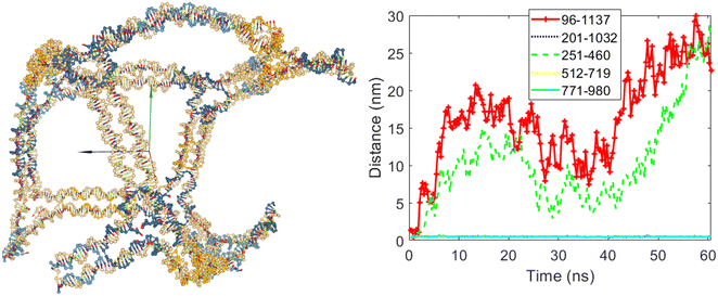 | ||
| Fig. 7 The final structure and the distances graph between bases on edges with scaffold crossover after simulation for the case where edges number three and six are allowed to open. | ||
For the second case, edges numbered five and eight were set to open, while edges three, six, and ten were set to remain closed. Fig. 8 shows the cubic nanostructure and the distances graph of the selected bases for this scenario after the coarse-grained simulation. As expected, two of the twelve edges of the cube opened. The graph in Fig. 8 indicates the increase in distances for the bases belonging to edges five and eight after the start of the simulation. Specifically, the distances between bases 201 and 1032 (belonging to edge number five) and bases 512 and 719 (belonging to edge number eight) increased, confirming that these edges were permitted to open during the design phase.
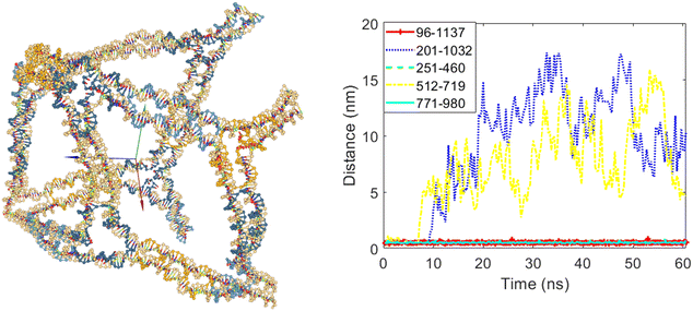 | ||
| Fig. 8 The final structure and the distances graph between bases on edges with scaffold crossover after simulation for the case where edges number five and eight are allowed to open. | ||
Fig. 9 illustrates the cubic nanostructure and the distances graph of the selected bases for the third scenario after the coarse-grained simulation. In this scenario, edges numbered eight and ten were set to open, while edges numbered three, five, and six were set to remain closed. The nanostructure and distances graph in Fig. 9 confirm this configuration. After the simulation, two of the twelve edges of the cube have opened, as evidenced by the increased distances for the bases associated with edges eight and ten shown in the graph.
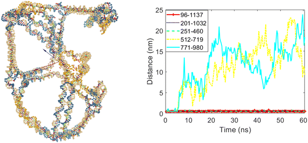 | ||
| Fig. 9 The final structure and the distances graph between bases on edges with scaffold crossover after simulation for the case where edges number eight and ten are allowed to open. | ||
The final case of this scenario involves allowing edges numbered five and ten to open, while edges numbered three, six, and eight were set to remain closed. Fig. 10 shows the cubic nanostructure and the distances graph of the selected bases for this final case after the coarse-grained simulation. As expected, two of the twelve edges of the cube opened after the simulation, and according to the graph in Fig. 10, the opened edges are five and ten.
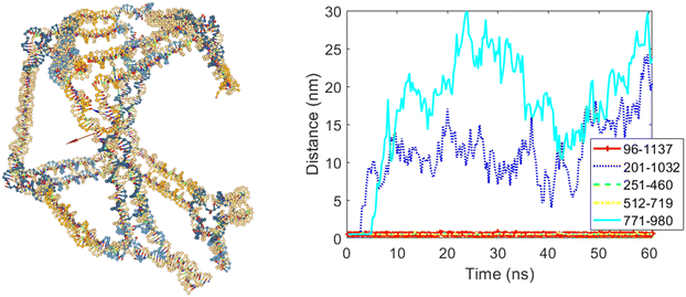 | ||
| Fig. 10 The final structure and the distances graph between bases on edges with scaffold crossover after simulation for the case where edges number five and ten are allowed to open. | ||
In the next step, a scenario was designed using the modified DAEDALUS software code, allowing three out of the five edges to open. In this design, edges numbered five, eight, and ten were set to open, while edges numbered three and six were set to remain closed. Fig. 11 clearly shows that three of the twelve edges of the cube opened after the simulation. The graph in Fig. 11 also shows the increase in distances between bases 201 and 1032 (belonging to edge five), bases 512 and 719 (belonging to edge eight), and bases 771 and 980 (belonging to edge ten) during the simulation period. The distances between the bases belonging to edges three and six did not increase, confirming that these edges remained closed.
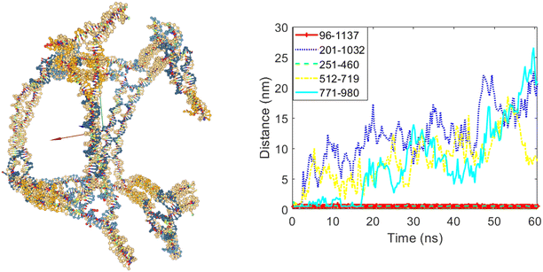 | ||
| Fig. 11 The final structure and the distances graph between bases on edges with scaffold crossover after simulation for the case where edges number five, eight and ten are allowed to open. | ||
The next design and simulation scenario involves allowing four out of the five edges to open. In this case, edge number three was selected to remain closed, while edges five, six, eight, and ten were allowed to open. Fig. 12 shows the cubic nanostructure and the distances graph of the selected bases after the simulation. It is evident that four of the twelve edges of the cube opened, as indicated by the increased distances between the selected bases in these four edges. In contrast, the distance between bases 96 and 1137, belonging to edge number three, did not increase, confirming that this edge remained closed.
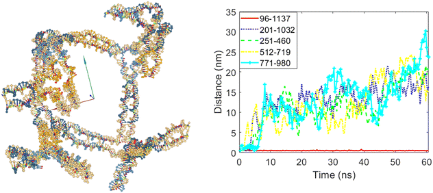 | ||
| Fig. 12 The final structure and the distances graph between bases on edges with scaffold crossover after simulation for the case where edges number five, six, eight and ten are allowed to open. | ||
The final design subjected to simulation involves setting ‘A’ to 0 for all five edges numbered three, five, six, eight, and ten. This configuration allows these five edges to open. The last row of Fig. 5 shows illustrates the cubic nanostructure and the distances graph of the selected bases after the simulation for this final scenario. As shown in the last row of Fig. 5 shows, five out of the twelve edges of the cube have opened. The remaining seven edges can never be opened due to the lack of scaffold crossovers. These five edges, which have scaffold crossovers, can open, and their opening can be controlled by adjusting the position of their staple strands. The graph in the last row of Fig. 5 shows also depicts the increase in distances between the bases belonging to these five edges.
4. Conclusion
In this study, various controlled nanostructures were designed and simulated based on wireframe DNA origami. To achieve this, the DAEDALUS software code was modified. The modified code, similar to the original, automatically designs controlled wireframe DNA origami nanostructures by processing a PLY file of the desired 3D shape and the minimum edge length. Consequently, these adjustments were seamlessly modified into the design process, ensuring the creation of controlled nanostructures. These modifications are versatile and can be applied to all 3D wireframe DNA origami structures, not just cubes. Initially, a stable and non-opening structure was designed using the unmodified code. Subsequently, other structures with the capability to open in a controlled manner were designed using the modified DAEDALUS code. Coarse-grained model was employed to simulate the designed nanostructures, demonstrating that DNA origami structures can indeed be designed to open in a controlled fashion. This study presents several nanostructures with edges that can be selectively opened, allowing the release of payloads such as drugs. This capability promises significant advancements in smart drug delivery systems in the medical field. Furthermore, these structures have potential applications as components in intelligent nanorobots.Data availability
All data that support the findings of this study are included within the article.Conflicts of interest
There are no conflicts to declare.References
- A. Ghaffari, A. Shokuhfar and R. H. Ghasemi, Capturing and releasing a nano cargo by Prefoldin nano actuator, Sens. Actuators, B, 2012, 171, 1199–1206 Search PubMed
.
- M. Keramati and R. H. Ghasemi, A molecular dynamics investigation of the effects of mutation on Prefoldin nano actuator in inhibiting amyloid β42-dimer, Sens. Actuators, B, 2017, 248, 536–544 Search PubMed
.
-
T. E. Ouldridge, Coarse-grained modelling of DNA and DNA self-assembly, Springer Science & Business Media, 2012 Search PubMed
.
-
N. C. Seeman, Structural DNA nanotechnology, Cambridge University Press, 2015 Search PubMed
.
- N. C. Seeman, Nucleic acid junctions and lattices, J. Theor. Biol., 1982, 99(2), 237–247 Search PubMed
.
- P. W. Rothemund, Folding DNA to create nanoscale shapes and patterns, Nature, 2006, 440(7082), 297–302 CAS
.
- S. Dey, C. Fan, K. V. Gothelf, J. Li, C. Lin, L. Liu, N. Liu, M. A. Nijenhuis, B. Saccà, F. C. Simmel and H. Yan, DNA origami, Nat. Rev. Methods Primers, 2021, 1(1), 13 Search PubMed
.
- L. Qian, Y. Wang, Z. Zhang, J. Zhao, D. Pan, Y. Zhang, Q. Liu, C. Fan, J. Hu and L. He, Analogic China map constructed by DNA, Chin. Sci. Bull., 2006, 51, 2973–2976 CAS
.
- E. S. Andersen, M. Dong, M. M. Nielsen, K. Jahn, A. Lind-Thomsen, W. Mamdouh, K. V. Gothelf, F. Besenbacher and J. Kjems, DNA origami design of dolphin-shaped structures with flexible tails, ACS Nano, 2008, 2(6), 1213–1218 Search PubMed
.
- E. Benson, A. Mohammed, J. Gardell, S. Masich, E. Czeizler, P. Orponen and B. Högberg, DNA rendering of polyhedral meshes at the nanoscale, Nature, 2015, 523(7561), 441–444 CAS
.
- R. Khosravi, R. H. Ghasemi and R. Soheilifard, Design and simulation of a DNA origami nanopore for large cargoes, Mol. Biotechnol., 2020, 62(9), 423–432 CrossRef CAS
.
- Q. Shen, Q. Xiong, K. Zhou, Q. Feng, L. Liu, T. Tian, C. Wu, Y. Xiong, T. J. Melia, C. P. Lusk and C. Lin, Functionalized DNA-origami-protein nanopores generate large transmembrane channels with programmable size-selectivity, J. Am. Chem. Soc., 2022, 145(2), 1292–1300 CrossRef
.
- Z. Peng, S. Iwabuchi, K. Izumi, S. Takiguchi, M. Yamaji, S. Fujita, H. Suzuki, F. Kambara, G. Fukasawa, A. Cooney and L. Di Michele, Lipid vesicle-based molecular robots, Lab Chip, 2024, 24, 996–1029 RSC
.
- H. Dietz, S. M. Douglas and W. M. Shih, Folding DNA into twisted and curved nanoscale shapes, Science, 2009, 325(5941), 725–730 CrossRef CAS PubMed
.
- D. Han, S. Pal, J. Nangreave, Z. Deng, Y. Liu and H. Yan, DNA origami with complex curvatures in three-dimensional space, Science., 2011, 332(6027), 342–346 CrossRef CAS
.
- M. Mogheiseh, G. R. Hasanzadeh and R. Soheilifard, The effect of crossovers on the stability of DNA origami type nanocarriers, Multidiscip. Model. Mater. Struct., 2021, 17(2), 426–436 CrossRef CAS
.
- M. Mogheiseh and R. H. Ghasemi, An analysis of the capturing and passing ability of a DNA origami nanocarrier with the aid of molecular dynamics simulation, Mol. Biotechnol., 2023, 65(8), 1287–1295 CrossRef CAS PubMed
.
- M. Mogheiseh, E. Etemadi and G. R. Hasanzadeh, Design, molecular dynamics simulation, and investigation of the mechanical behavior of DNA origami nanotubes with auxetic and honeycomb structures, J. Biomol. Struct. Dyn., 2023, 41(24), 14822–14831 CrossRef CAS PubMed
.
- J. M. Parikka, H. Järvinen, K. Sokołowska, V. Ruokolainen, N. Markešević, A. K. Natarajan, M. Vihinen-Ranta, A. Kuzyk, K. Tapio and J. J. Toppari, Creation of ordered 3D tubes out of DNA origami lattices, Nanoscale, 2023, 15(17), 7772–7780 RSC
.
- S. Dastorani, M. Mogheiseh, R. H. Ghasemi and R. Soheilifard, Modelling and structural investigation of a new DNA Origami based flexible bio-nano joint, Mol. Simul., 2020, 46(13), 994–1003 CrossRef CAS
.
- Y. Wang, A. Kucinic, L. Des Rosiers, P. E. Beshay, N. Wile, M. W. Hudoba and C. E. Castro, Mechanical Design of DNA Origami in the Classroom, Appl. Sci., 2023, 13(5), 3208 CrossRef CAS
.
- A. Peil, P. Zhan, X. Duan, R. Krahne, D. Garoli, L. Liz-Marzán and N. Liu, Transformable plasmonic helix with swinging gold nanoparticles, Angew. Chem., Int. Ed., 2023, 62(9), e202213992 Search PubMed
.
-
P. E. Beshay, J. A. Johson, J. V. Le and C. E. Castro, Design, assembly, and function of DNA origami mechanisms, in DNA and RNA Origami: Methods and Protocols, Springer US, New York, NY, 2023, pp. 21–49 Search PubMed
.
- Y. C. Zeng, O. J. Young, L. Si, M. W. Ku, G. Isinelli, A. Rajwar, A. Jiang, C. M. Wintersinger, A. R. Graveline, A. Vernet and M. Sanchez, DNA origami vaccine (DoriVac) nanoparticles improve both humoral and cellular immune responses to infectious diseases, bioRxiv, 2024, preprint, DOI:10.1101/2023.12.29.573647.
- M. Kumar, A. Jha and B. Mishra, DNA-Based Nanostructured Platforms as Drug Delivery Systems, Chem Bio Eng., 2024, 1(3), 179–198 CrossRef CAS
.
- F. Zhang, S. Jiang, S. Wu, Y. Li, C. Mao, Y. Liu and H. Yan, Complex wireframe DNA origami nanostructures with multi-arm junction vertices, Nat. Nanotechnol., 2015, 10(9), 779–784 CAS
.
- E. Benson, A. Mohammed, A. Bosco, A. I. Teixeira, P. Orponen and B. Högberg, Computer-aided production of scaffolded DNA nanostructures from flat sheet meshes, Angewandte Chemie International Edition., 2016, 55(31), 8869–8872 CAS
.
- S. M. Douglas, A. H. Marblestone, S. Teerapittayanon, A. Vazquez, G. M. Church and W. M. Shih, Rapid prototyping of 3D DNA-origami shapes with caDNAno, Nucleic Acids Res., 2009, 37(15), 5001–5006 CrossRef CAS PubMed
.
- S. Williams, K. Lund, C. Lin, P. Wonka, S. Lindsay and H. Yan, Tiamat: A three-dimensional editing tool for complex DNA structures. In DNA Computing: 14th International Meeting on DNA Computing, DNA 14. Revised Selected Papers 14 2009, Springer Berlin Heidelberg, Prague, Czech Republic, 2008, pp. 90–101 Search PubMed.
- R. Veneziano, S. Ratanalert, K. Zhang, F. Zhang, H. Yan, W. Chiu and M. Bathe, Designer nanoscale DNA assemblies programmed from the top down, Science, 2016, 352(6293), 1534 CrossRef CAS
.
- H. Jun, F. Zhang, T. Shepherd, S. Ratanalert, X. Qi, H. Yan and M. Bathe, Autonomously designed free-form 2D DNA origami, Sci. Adv., 2019, 5(1), eaav0655 CrossRef PubMed
.
- H. Jun, T. R. Shepherd, K. Zhang, W. P. Bricker, S. Li, W. Chiu and M. Bathe, Automated sequence design of 3D polyhedral wireframe DNA origami with honeycomb edges, ACS Nano, 2019, 13(2), 2083–2093 CAS
.
- H. Jun, X. Wang, W. P. Bricker and M. Bathe, Automated sequence design of 2D wireframe DNA origami with honeycomb edges, Nat. Commun., 2019, 10(1), 5419 CrossRef
.
- H. Jun, X. Wang, M. F. Parsons, W. P. Bricker, T. John, S. Li, S. Jackson, W. Chiu and M. Bathe, Rapid prototyping of arbitrary 2D and 3D wireframe DNA origami, Nucleic Acids Res., 2021, 49(18), 10265–10274 CrossRef CAS
.
- E. Benson, A. Mohammed, D. Rayneau-Kirkhope, A. Gådin, P. Orponen and B. Hogberg, Effects of design choices on the stiffness of wireframe DNA origami structures, ACS Nano, 2018, 12(9), 9291–9299 CrossRef CAS PubMed
.
- Y. Wang, E. Benson, F. Fördős, M. Lolaico, I. Baars, T. Fang, A. I. Teixeira and B. Högberg, DNA origami penetration in cell spheroid tissue models is enhanced by wireframe design, Adv. Mater., 2021, 33(29), 2008457 CrossRef CAS PubMed
.
- X. Wang, S. Li, H. Jun, T. John, K. Zhang, H. Fowler, J. P. Doye, W. Chiu and M. Bathe, Planar 2D wireframe DNA origami, Sci. Adv., 2022, 8(20), eabn0039 CAS
.
- T. E. Ouldridge, A. A. Louis and J. P. Doye, Structural, mechanical, and thermodynamic properties of a coarse-grained DNA model, The Journal of chemical physics., 2011, 134(8), 085101 Search PubMed
.
- B. E. Snodin, F. Randisi, M. Mosayebi, P. Šulc, J. S. Schreck, F. Romano, T. E. Ouldridge, R. Tsukanov, E. Nir, A. A. Louis and J. P. Doye, Introducing improved structural properties and salt dependence into a coarse-grained model of DNA, J. Chem. Phys., 2015, 142(23), 234901 CrossRef PubMed
.
- P. Šulc, F. Romano, T. E. Ouldridge, L. Rovigatti, J. P. Doye and A. A. Louis, Sequence-dependent thermodynamics of a coarse-grained DNA model, J. Chem. Phys., 2012, 137(13), 135101 Search PubMed
.
- E. Poppleton, J. Bohlin, M. Matthies, S. Sharma, F. Zhang and P. Šulc, Design, optimization and analysis of large DNA and RNA nanostructures through interactive visualization, editing and molecular simulation, Nucleic Acids Res., 2020, 48(12), e72 CAS
.
- J. Bohlin, M. Matthies, E. Poppleton, J. Procyk, A. Mallya, H. Yan and P. Šulc, Design and simulation of DNA, RNA and hybrid protein–nucleic acid nanostructures with oxView, Nat. Protoc., 2022, 17(8), 1762–1788 CAS
.
- M. Mogheiseh and G. R. Hasanzadeh, Design and simulation of a wireframe DNA origami nanoactuator, J. Chem. Phys., 2024, 161(4), 045101 CAS
.
-
J. P. Doye, H. Fowler, D. Prešern, J. Bohlin, L. Rovigatti, F. Romano, P. Šulc, C. K. Wong, A. A. Louis, J. S. Schreck and M. C. Engel, The oxDNA coarse-grained model as a tool to simulate DNA origami, in DNA and RNA Origami: Methods and Protocols, Springer US, New York, NY, 2023, pp. 93–112 Search PubMed
.
- A. Suma,
et al., TacoxDNA: a user-friendly web server for simulations of complex DNA structures, from single strands to origami, J. Comput. Chem., 2019, 40, 2586–2595 CrossRef CAS PubMed
.
| This journal is © The Royal Society of Chemistry 2025 |

