Effects of porous hedgehog-like morphology and graphene oxide on the cycling stability and rate performance of Co3O4/NiO microspheres†
Guozhen
Zhu‡
 *a,
Xinsong
Xu‡
b,
Yiyao
Zhang
a,
Jiale
Lian
a,
Yuhan
Li
a,
Zhen
Yang
 *a and
Renchao
Che
 *b
*b
aSchool of Chemical Engineering, Jiangxi Normal University, Nanchang 330022, P. R. China. E-mail: zhuguozhen@jxnu.cn; Yangzhen@jxnu.edu.cn
bLaboratory of Advanced Materials, Shanghai Key Lab of Molecular Catalysis and Innovative Materials, Academy for Engineering & Technology, Advanced Coatings Research Center of Ministry of Education of China, Fudan University, Shanghai 200438, P. R. China. E-mail: rcche@fudan.edu.cn
First published on 11th January 2025
Abstract
A porous hedgehog-like Co3O4/NiO/graphene oxide (denoted as PHCNO/GO) microsphere was prepared by a facile solvothermal method, followed by an annealing treatment under argon atmosphere. Benefiting from the thin Co3O4/NiO nanosheets with a large specific surface area, abundant pores distributed between the Co3O4/NiO nanosheets, and GO firmly wrapped around the surface of PHCNO microspheres, the PHCNO/GO microspheres showed excellent lithium storage performance. The Co3O4/NiO nanosheets provided numerous active sites, achieving a high reversible specific capacity. The pores distributed between the Co3O4/NiO nanosheets created numerous diffusion pathways for lithium ions and relieved stress from the charging/discharging process. Meanwhile, GO supported the PHCNO microspheres, enhancing their cycling stability. A high reversible specific capacity of 383.9 mA h g−1 was maintained after 1000 cycles at 3000 mA g−1. In addition, GO improved the conductivity of PHCNO microspheres and then achieved a good rate performance; a high reversible specific capacity of 526.7 mA h g−1 was obtained at 5000 mA g−1. This work provided a reference for synthesizing high-performance lithium-ion battery anode materials.
New conceptsGraphite, Li4Ti5O12, and silicon are considered ideal anode materials for lithium-ion batteries due to their fast charging speed, long cycle life, and high specific capacity. However, their practical applications are greatly restricted by low potential platforms, low theoretical specific capacity, and large volume expansion. Transition metal oxides are ideal anode material due to their high theoretical specific capacity and environmental friendliness. The hard-template method has often been used to synthesize materials with various morphologies and sizes. However, its application is limited by difficulties in template removal, high costs, size limitations of porous materials, and complex operations. In this work, a porous hedgehog-like Co3O4/NiO/graphene oxide microsphere was synthesized using a facile solvothermal method, followed by an annealing treatment under argon atmosphere. The porous hedgehog-like Co3O4/NiO/graphene oxide microspheres exhibited excellent lithium storage performance due to their unique structural design, graphene oxide encapsulation, and contribution of pseudo-capacitance. This work provides a new approach for high-performance anode materials for lithium-ion batteries, nanoscience and nanotechnology. |
1 Introduction
Developing renewable energy is the key to achieving the goals of carbon peaking and carbon neutralization. Electric vehicles powered by lithium-ion batteries can effectively reduce tailpipe emissions, prevent carbon dioxide emissions, and help achieve the double carbon goal.1,2 Thus, the synthesis of high-performance lithium-ion batteries is particularly important.3–5 Anode materials play an important role in improving the performance of lithium-ion batteries. Graphite with a fast charging speed (80% capacity obtained after charging for 6 minutes at 10C),6 Li4Ti5O12 with a long cycle life (no significant capacity degradation during 20![[thin space (1/6-em)]](https://www.rsc.org/images/entities/char_2009.gif) 000 cycles at 30C),7 and silicon with high specific capacity (3592 mA h g−1)8 are considered ideal anode materials. However, their practical applications were greatly restricted by low potential platforms, low theoretical specific capacity, and large volume expansion. Transition metal oxides are considered ideal anode materials due to their high theoretical specific capacity and environmental friendliness.9,10 Nevertheless, the cycling stability is greatly restricted by the slow kinetic and poor structural stability,11–13 and the rate performance is inhibited by its poor conductivity.14–16
000 cycles at 30C),7 and silicon with high specific capacity (3592 mA h g−1)8 are considered ideal anode materials. However, their practical applications were greatly restricted by low potential platforms, low theoretical specific capacity, and large volume expansion. Transition metal oxides are considered ideal anode materials due to their high theoretical specific capacity and environmental friendliness.9,10 Nevertheless, the cycling stability is greatly restricted by the slow kinetic and poor structural stability,11–13 and the rate performance is inhibited by its poor conductivity.14–16
It is obvious that morphology plays a significant impact on the cycling stability of transition metal oxides. In recent years, transition metal oxides with different morphologies have been reported.17–20 CHS@CG was synthesized by a molecular precursor pyrolysis strategy. Benefiting from the yolk–shell hollow nanosphere structure, the diffusion path of lithium ions was greatly shortened, and the contact area between the electrode and electrolyte was effectively increased, and enough buffer space was provided. CHS@CG showed excellent cycling stability (831 mA h g−1 after 400 cycles at 0.2C) and high coulombic efficiency (nearly 100%).21 Graphene embed Co3O4 rose-spheres were synthesized by the hydrothermal method and electrostatic self-assembly process, which exhibited a high reversible specific capacity (1110.8 mA h g−1 at 90 mA g−1) and an excellent rate performance (462.3 mA h g−1 at 1800 mA g−1) due to the novel graphene-embedded Co3O4 rose-spheres structure.22 It was evident that GO could greatly improve the rate performance of transition metal oxides.23–27 A multihierarchical heterostructure GO/NiCo2O4/Co3O4 composite was fabricated by the self-template method. Benefiting from the elaborate nanostructure and synergy of components, an excellent rate performance was obtained (649.1 mA h g−1 at 10 A g−1).28 Benefiting from the special heterostructure, the charge-transfer kinetics could be significantly improved, and the electrode material structure could be stabilized, and the ion diffusion energy barrier could be reduced, and then the rate performance could be improved.29,30 N-C@Co3O4-CoO-@GO with 3D porous conductive network structure was prepared by the facile hydrothermal method, and a high reversible specific capacity of 725.1 mA h g−1 was achieved at 5 A g−1.31
In this work, CNO microspheres with different morphologies were prepared by controlling the types of surfactants. Compared with other spheres, PHCNO/GO microspheres exhibited the most excellent cycling stability and rate performance due to thin Co3O4/NiO nanosheets, abundant pores distributed between Co3O4/NiO nanosheets, and GO firmly wrapped on the surface of PHCNO microspheres.
2 Experimental section
2.1 Materials
Cobalt nitrate, nickel nitrate, 2-methylimidazole, 1,3,5-benzoic acid, cetyltrimethylammonium bromide, sodium dodecyl benzene sulfonate, N,N-dimethyl bromide methyl formamide, GO, and absolute ethanol were purchased from Macklin Reagent Co., Ltd.2.2 Preparation of PHCNO microspheres
The synthesis process of PHCNO microspheres is shown in Fig. 1a. 0.1 g of cobalt nitrate, 0.05 g of nickel nitrate, 0.04 g of 2-methylimidazole, 0.105 g of 1,3,5-benzoic acid, and 0.1 g of cetyltrimethylammonium bromide were mixed with 35 mL of N,N-dimethyl bromide methyl formamide, and continuously stirred until a uniform solution appeared. Then, a solution was poured into the Teflon pot sealed inside the stainless steel sealed autoclave, and maintained for 24 h at 180 °C, PHCNO microsphere precursor powders were obtained by alternately centrifuging treatment with absolute ethanol and deionized water and subsequently drying treatment at 80 °C for 12 h. Finally, precursor powders were annealed treatment for at 800 °C 10 h in an air atmosphere to obtain PHCNO microspheres.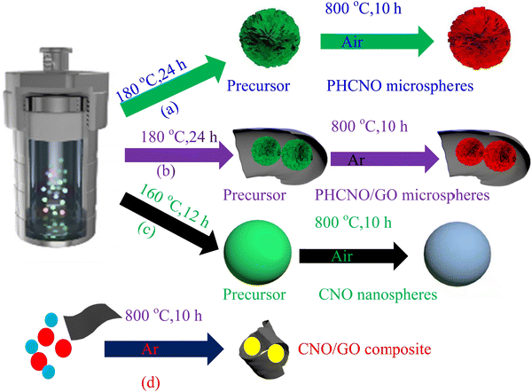 | ||
| Fig. 1 Synthesis process of (a) PHCNO microspheres, (b) PHCNO/GO microspheres, (c) CNO nanospheres, and (d) CNO/GO composite. | ||
2.3 Preparation of PHCNO/GO microspheres
The synthesis process of PHCNO/GO microspheres is shown in Fig. 1b. 0.1 g of cobalt nitrate, 0.05 g of nickel nitrate, 0.04 g of 2-methylimidazole, 0.105 g of 1,3,5-benzoic acid, 0.1 g of cetyltrimethylammonium bromide, and 0.05 g of GO were mixed with 35 mL of N,N-dimethyl bromide methyl formamide, and continuously stirred until uniformly suspension appeared. Then, the solution was poured into the Teflon pot sealed inside the stainless steel sealed autoclave, and maintained at 180 °C for 24 h; PHCNO/GO microspheres precursor powders were obtained by alternately centrifuging treatment with absolute ethanol and deionized water and subsequently drying treatment at 80 °C for 12 h. Finally, the precursor powders were annealed at 800 °C for 10 h under flowing Ar atmosphere to obtain PHCNO/GO microspheres.2.4 Preparation of CNO nanospheres
The synthesis process of CNO nanospheres is shown in Fig. 1c. Cobalt nitrate (0.1 g), nickel nitrate (0.05 g), 2-methylimidazole (0.04 g), sodium dodecyl benzene sulfonate (0.1 g), and 1,3,5-benzoic acid (0.105 g) were mixed with 35 mL of N,N-dimethyl bromide methyl formamide, and continuously stirred until a uniform solution appeared. Then, the solution was poured into the Teflon pot sealed inside the stainless steel sealed autoclave, and maintained at 160 °C for 12 h, CNO nanosphere precursor powders were obtained by alternating the centrifuging treatment with absolute ethanol and deionized water and subsequently drying treatment at 80 °C for 12 h. Finally, the precursor powders were annealed treatment at 800 °C for 10 h in air atmosphere to obtain CNO nanospheres.2.5 Preparation of CNO/GO composite
The synthesis process of the CNO/GO composite is shown in Fig. 1d. 0.5 g of cobalt nitrate, 0.25 g of nickel nitrate, and 0.05 g of GO were mixed to obtain mixed powders, which were annealed treatment at 800 °C for 10 h under a flowing Ar atmosphere to obtain CNO/composite.2.6 Material characterization
The phase purity of the prepared samples was determined by X-ray diffraction (Bruker D8 Advance, Cu target, Kα1 = 1.54056 Å, Kα2 = 1.54439 Å). The morphologies of the synthesized samples were observed using a field-emission scanning electron microscope (Hitachi, S-4800) and transmission electron microscope (JEOL, JEM-2100F). The carbon content was measured using a thermogravimetric analyzer (Pyris1TGA). The specific surface area and pore size distribution of the synthesized samples were measured using a specific surface and aperture analyzer (ASAP2020). The molecular structure and atomic valence states of the synthesized samples were analyzed by X-ray photoelectron spectroscopy (Axis Ultra DLD).2.7 Electrochemical performance measurement
The assembly process of the button battery is as follows. (a) The substance, polyvinylidene fluoride, and acetylene black were weighed according to the mass ratio of 8![[thin space (1/6-em)]](https://www.rsc.org/images/entities/char_2009.gif) :
:![[thin space (1/6-em)]](https://www.rsc.org/images/entities/char_2009.gif) 1
1![[thin space (1/6-em)]](https://www.rsc.org/images/entities/char_2009.gif) :
:![[thin space (1/6-em)]](https://www.rsc.org/images/entities/char_2009.gif) 1, and mixed with N-methylpyrrolidone, and continuously stirred until a slurry with good fluidity was obtained. (b) Slurry was scraped onto copper foil using a doctor blade (0.5 mm) and vacuum dried for 12 h at 80 °C. (c) The copper foil was stamped into the discs with a diameter of 12 mm, and vacuum dried for 12 h at 80 °C. (d) Disc, metal lithium sheet (1.5 mm), polypropylene microporous membrane, and electrolyte including LiPF6 (1 mol L−1), mixed with diethyl carbonate and ethylene carbonate (1
1, and mixed with N-methylpyrrolidone, and continuously stirred until a slurry with good fluidity was obtained. (b) Slurry was scraped onto copper foil using a doctor blade (0.5 mm) and vacuum dried for 12 h at 80 °C. (c) The copper foil was stamped into the discs with a diameter of 12 mm, and vacuum dried for 12 h at 80 °C. (d) Disc, metal lithium sheet (1.5 mm), polypropylene microporous membrane, and electrolyte including LiPF6 (1 mol L−1), mixed with diethyl carbonate and ethylene carbonate (1![[thin space (1/6-em)]](https://www.rsc.org/images/entities/char_2009.gif) :
:![[thin space (1/6-em)]](https://www.rsc.org/images/entities/char_2009.gif) 1 v/v), were assembled into a button battery in a glove box filled with argon gas. A Land battery measurement system (CT2001A) and electrochemical workstation (CHI604D) were used to test the electrochemical performance.
1 v/v), were assembled into a button battery in a glove box filled with argon gas. A Land battery measurement system (CT2001A) and electrochemical workstation (CHI604D) were used to test the electrochemical performance.
3 Results and discussion
3.1 Characterization of samples
XRD patterns of PHCNO/GO microspheres, PHCNO microspheres, and CNO nanospheres are shown in Fig. 2a. Diffraction peaks appeared at 31.2°, 59.3°, and 65.3° corresponding to (220), (511), and (440) crystal planes of Co3O4 (PDF#43-1003), and diffraction peaks located at 37.3°, 43.3°, 62.8°, 75.5°, and 79.3° could be ascribed to (111), (200), (220), (311), and (222) crystal planes of NiO (PDF#47-1049), respectively, illustrating the successful synthesis of PHCNO/GO microspheres, PHCNO microspheres, and CNO nanospheres. Raman spectra of PHCNO microspheres, PHCNO/GO microspheres, and CNO nanospheres are exhibited in Fig. 2b. Compared with PHCNO microspheres and CNO nanospheres, a significant D-band peak (1326 cm−1) and G-bank peak (1600 cm−1) of carbon appeared in the PHCNO/GO microspheres, illustrating that GO was successfully wrapped on the surface of PHCNO microspheres. The disordered D-band peak appeared at 1326 cm−1 indicating that GO contained crystal defects, which was conducive to enhancing the diffusion rate of lithium ions, and accelerating the transfer of electrons, and then achieving an excellent rate performance.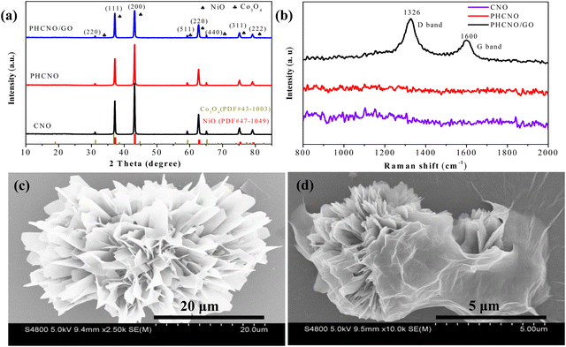 | ||
| Fig. 2 (a) XRD patterns, (b) Raman spectra of the PHCNO microspheres, PHCNO/GO microspheres and CNO nanospheres, SEM images of (c) PHCNO microspheres and (d) PHCNO/GO microspheres. | ||
SEM images of PHCNO microspheres, PHCNO/GO microspheres, and CNO nanospheres are shown in Fig. 2c and d, Fig. S1 (ESI†), and Fig. 3a. A hedgehog-like microsphere was observed, which was assembled from numerous CNO nanosheets (Fig. 2c). A large number of pores were distributed between CNO nanosheets (Fig. 2c), and CNO nanosheets with large specific surface areas could provide numerous active sites for the diffusion of lithium ions.32 GO (Fig. 2d and Fig. S1, ESI†) tightly wrapped on the surface of PHCNO microspheres constructed a conductive network to improve the rate performance, and provided support for microspheres to enhance the cycling stability. As a comparison, CNO nanospheres with a diameter of 100 nm were synthesized (Fig. 3a), but the dense microsphere surface was not beneficial for the enhancement of lithium storage performance. TEM images of PHCNO/GO microspheres are shown in Fig. 3b and c, a large number of CNO nanosheets were assembled into microspheres, and GO was firmly wrapped on the surface of PHCNO microspheres. The lattice fringes with crystal plane spacing of 0.17 nm and 0.40 nm displayed (220) crystal plane of Co3O4 and (311) crystal plane of NiO, respectively (Fig. 3d), further confirming the successful synthesis of PHCNO microspheres. N2 adsorption/desorption profiles of PHCNO microspheres, PHCNO/GO microspheres, and CNO nanospheres are shown in Fig. S2 (ESI†). Owning to the abundant pores distributed between the CNO nanosheets; the specific surface area of PHCNO/GO microspheres (106.86 m2 g−1) was higher than that of CNO nanospheres (34.29 m2 g−1). A large specific surface area was beneficial for improving the lithium storage performance.
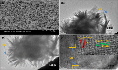 | ||
| Fig. 3 (a) SEM image of CNO nanospheres, (b) and (c) TEM and (d) HRTEM images of PHCNO/GO microspheres. | ||
3.2 Electrochemical performance and analysis
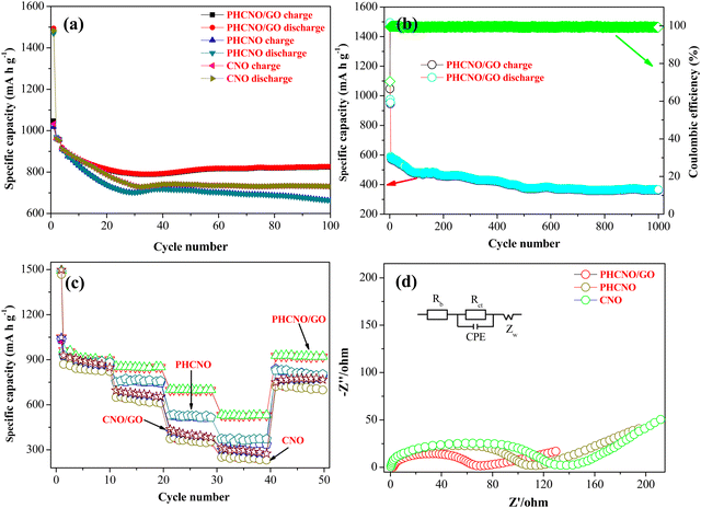
Fig. 4a exhibits the cycling stability of the PHCNO/GO microspheres, PHCNO microspheres, and CNO nanospheres at 500 mA g−1. The irreversible specific capacity loss during the initial cycling process occurred on three spheres, and the specific capacity increased gradually after several cycles due to the activation process of the materials.33 PHCNO/GO microspheres exhibited the highest charge and discharge-specific capacities during the 100 cycles. The reversible specific capacity of PHCNO/GO microspheres was as high as 822.9 mA h g−1 after 100 cycles, and the capacity retention of 89% was retained. The cycling stability of the three spheres for 1000 cycles at 3000 mA g−1 was evaluated to further identify the excellent cycling stability of PHCNO/GO microspheres (Fig. 4b). Significantly capacity decay was not observed after 500 cycles, and the high reversible specific capacity of 383.9 mA h g−1 was obtained after 1000 cycles. Most porous hedgehog-like microspheres were still maintained after 1000 cycles (Fig. S3, ESI†), confirming that PHCNO/GO microspheres were extremely stable. Galvanostatic charge/discharge profiles of PHCNO/GO microspheres, PHCNO microspheres, and CNO nanospheres are shown in Fig. S4 (ESI†). PHCNO/GO microspheres showed the smallest gap between the second cycle and the 100th cycle, identifying the most excellent cycle reversibility of PHCNO/GO microspheres.Fig. 4c exhibits the rate performance of PHCNO/GO microspheres, PHCNO microspheres, and CNO nanospheres, charge specific capacity and discharge-specific capacity decreased with the increase of the current density, which was the result of electrode polarization.34 PHCNO/GO microspheres exhibited the highest charge and discharge-specific capacity at different current densities. The average reversible specific capacities were 917.7 mA h g−1, 848.3 mA h g−1, 700.4 mA h g−1, 526.7 mA h g−1, and 917.3 mA h g−1 at 500 mA g−1, 1000 mA g−1, 3000 mA g−1, 5000 mA g−1, and 500 mA g−1, respectively, indicating the excellent rate performance of the PHCNO/GO microspheres.
What is more, PHCNO/GO microspheres displayed a better rate performance than that reported for most cobalt oxide materials (Table S1, ESI†).35–41
Fig. 4d exhibits the Nyquist plots with the corresponding equivalent circuit of PHCNO/GO microspheres, PHCNO microspheres, and CNO nanospheres. Rs, Rct, CPE, and Zw in equivalent circuits express the internal bulk resistance, charge-transfer resistance, double-layer capacitance, and Warburg resistance, respectively. Rct value of PHCNO/GO microspheres was as low as 86.68 Ω, which was greatly lower than that of PHCNO microspheres (115.26 Ω) and CNO nanospheres (186.34 Ω) (Table S2, ESI†), confirming that the wrapped GO improved the conductivity of PHCNO microspheres, and accelerated the electron transfer. Fig. S6 (ESI†) shows σ values of PHCNO/GO microspheres, PHCNO microspheres, and CNO nanospheres, which were calculated by the Warburg coefficient. According to the formula of D = R2T2/2A2n4F4C2σ2, the diffusion coefficient (D) of lithium ions was inversely proportional to the square of the σ value, the minimum σ value indicated the maximum lithium-ion diffusion coefficient and the strongest lithium-ion diffusion capability of PHCNO/GO microspheres.
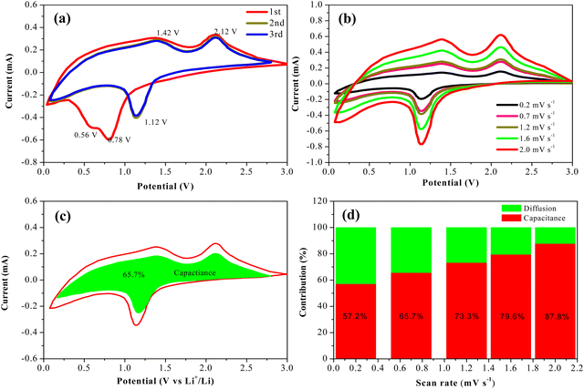
Cyclic voltammetry profiles of the first three cycles of PHCNO/GO microspheres were obtained to analyze the electrochemical reaction process (Fig. 5a). The clearly visible reduction peaks that appeared at 0.56 V of the initial cathodic scan corresponded to the reduction reaction Co3O4 to Co and NiO to Ni, and the reduction peak located at 0.78 V represented the solid electrolyte interface films.42 The reduction peak intensity of the second cathodic scan was lower than that of the first cathodic scan, indicating that the solid electrolyte interface films were formed. A high-degree overlap occurred on the reduction peaks of the last two cathodic scans, indicating the existence of extremely stable solid electrolyte interface films.43,44 Oxidation peaks appeared at 1.42 V and 2.12 V of the initial anodic scan representing the oxidation reaction Co to Co3O4 and Ni to NiO, accompanied by the decomposition of Li2O.45 A good coincidence occurred on two anodic scans, identifying the excellent cycling stability of the PHCNO/GO microspheres. Cyclic voltammetry profiles of the PHCNO/GO microspheres at various sweep rates are shown in Fig. 5b. The contribution ratio of the surface-induced pseudo-capacitance and diffusion capacitance could be confirmed by the formula of i(v) = k1v + k2v0.5 = avb.46,47 The fitted line slope of log(v) and log(i) represented b value. The b values of the oxidation and reduction peaks were 0.68 and 0.83, respectively (Fig. S7, ESI†), identifying that the charge storage process was controlled by diffusion capacitance and pseudo-capacitance. The pseudo-capacitance contribution ratio of 65.7% was confirmed at 0.7 mV s−1 (Fig. 5c), and the pseudo-capacitance contribution ratio increased with the increase of sweep rate (Fig. 5d).
The excellent lithium storage performance of PHCNO/GO microspheres could be ascribed to CNO nanosheets with large specific surface area, abundant pores, and GO wrapped on the surface of the PHCNO microspheres. CNO nanosheets provided numerous effective active sites for the full electrochemical reaction between the PHCNO microspheres and the electrolyte and then achieved a high reversible specific capacity. Meanwhile, the pores distributed between CNO nanosheets acted as diffusion pathways of lithium ions, and shortened the diffusion distance, and then enhanced the reversible specific capacity. Moreover, pores distributed between CNO nanosheets were conducive to accommodating the large volume change during the charging/discharging process and then improving the cycling stability. Owning to the support of GO for PHCNO microspheres, the cycling stability was further enhanced. Besides, the conductivity of PHCNO microspheres was greatly improved due to the wrapped GO, and the transfer of electrons was promoted, achieving a good rate performance.
4 Conclusion
In summary, we successfully prepared a porous hedgehog-like CNO/GO microspheres by the facile solvothermal method and annealing treatment in an argon atmosphere. Benefiting from the thin CNO nanosheets with large specific surface area, full contact between PHCNO microspheres and the electrolyte was achieved, and the high initial reversible specific capacity of 1047.7 mA h g−1 was obtained at 500 mA g−1. What is more, pores distributed between CNO nanosheets released the stress from the charging/discharging process, and the wrapped GO provided strong support for PHCNO microspheres, and then improved the cycling stability; the high reversible specific capacity of 383.9 mA h g−1 was maintained after 1000 cycles at 3000 mA g−1. Furthermore, a good rate performance was obtained due to the wrapped GO; the reversible specific capacity was as high as 526.7 mA h g−1 at 5000 mA g−1.Data availability
The data supporting the findings of this study are available upon request from the corresponding author.Conflicts of interest
The authors declare no competing financial interests.Acknowledgements
This work was supported by the National Natural Science Foundation of China (22263006, 52231007, 12327804, T2321003, 22088101), and in part by the National Key Research Program of China under Grant 2021YFA1200600, and Science and technology research project of Jiangxi Provincial Department of Education (GJJ200338).Notes and references
- X. Q. Zeng, M. Li, D. Abd El-Hady, W. Alshitari, A. Al-Bogami and J. Lu, Adv. Energy Mater., 2019, 9, 1900161 CrossRef.
- G. Harper, R. Sommerville, E. Kendrick, L. Driscoll, P. Slater, R. Stolkin, A. Walton, P. Christensen, O. Heidrich, S. Lambert, A. Abbott, K. Ryder, L. Gaines and P. Anderson, Nature, 2020, 575, 75–86 CrossRef PubMed.
- F. H. Gandoman, J. Jaguemont, S. Goutam, R. Gopalakrishnan, Y. Firouz, T. Kalogiannis, N. Omar and J. Mierlo, Appl. Energy, 2019, 251, 113343 CrossRef CAS.
- M. Weiss, R. Ruess, J. Kasnatscheew, Y. Levartovsky, N. Levy, P. Minnmann, L. Stolz, T. Waldmann, M. Mehrens, D. Aurbach, M. Winter, Y. Eli and J. Janek, Adv. Energy Mater., 2021, 11, 2101126 CrossRef CAS.
- G. Zubi, R. Dufo-Lopez, M. Carvalho and G. Pasaoglu, Renewable Sustainable Energy Rev., 2018, 89, 292–308 CrossRef.
- S. B. Tu, B. Zhang, Y. Zhang, Z. H. Chen, X. C. Wang, R. M. Zhan, Y. T. Ou, W. Y. Wang, X. R. Liu, X. R. Duan, L. Wang and Y. M. Sun, Nat. Energy, 2023, 8, 1365–1374 CrossRef CAS.
- C. Wang, S. Wang, Y. B. He, L. K. Tang, C. P. Han, C. Yang, M. Wagemaker, B. H. Li, Q. H. Yang, J. K. Kim and F. Y. Kang, Chem. Mater., 2015, 27, 5647–5656 CrossRef CAS.
- N. Kim, Y. J. Kim, J. Sung and J. Cho, Nat. Energy, 2023, 8, 921–933 CrossRef CAS.
- E. Duraisamy, E. Sujithkrishnan, K. Kannadasan, P. Prabunathan and P. Elumalai, J. Electroanal. Chem., 2021, 887, 115168 CrossRef CAS.
- A. P. Guo, X. Chen, J. K. Zhao, K. M. Yang, X. J. Zhang, C. Y. Ding and X. J. Yang, J. Colloid Interface Sci., 2023, 640, 829–838 CrossRef CAS PubMed.
- W. Kim, D. Shin, B. Seo, S. Chae, E. Jo and W. Choi, ACS Nano, 2022, 16, 17313–17325 CrossRef CAS PubMed.
- Q. M. Li, N. Han, J. L. Chai, W. Zhang, J. K. Du, H. Tian, H. Liu, G. X. Wang and B. H. Tang, Energy, 2023, 282, 128378 CrossRef CAS.
- X. Y. Hou, G. Zhou, D. D. Ai, R. H. Xi, Y. X. Yuan, J. L. Kang, H. Chen, J. M. Tian and J. T. Wang, J. Alloys Compd., 2023, 967, 171649 CrossRef CAS.
- J. X. Zhang, J. You, Q. Wei, J. I. Han and Z. M. Liu, Nanomaterials, 2023, 13, 1986 CrossRef CAS PubMed.
- J. T. Chen, K. T. Zhu, P. H. Liang, M. Wu, Y. Rao, H. J. Zheng, J. S. Liu, K. Yan and J. Wang, J. Mater. Chem. A, 2022, 10, 5273–5380 RSC.
- M. X. Cui, X. R. Chen, Z. C. Wang, S. Tao, D. J. Wu, B. Qian, L. W. Wang and P. K. Chu, J. Alloys Compd., 2022, 903, 163980 CrossRef CAS.
- R. Lu, Y. L. Tan, C. X. Yang, Y. W. Fan, X. Liang, H. Yuan and Y. F. Wang, Colloids Surf., A, 2022, 652, 129786 CrossRef CAS.
- X. Li, Q. Chu, M. Q. Song, C. H. Chen, Y. L. Li, X. D. Tian, Y. M. Cui and D. Y. Zhao, Appl. Surf. Sci., 2023, 618, 156658 CrossRef CAS.
- Z. Peng, X. J. Yin, T. L. Han, J. W. Long, J. P. Hei and J. Y. Liu, J. Alloys Compd., 2023, 968, 172085 CrossRef CAS.
- X. Zhang, Y. A. Liu, B. Zhu, H. Zhao, R. Y. Mi, Z. K. Wang and P. J. He, Appl. Phys. Lett., 2022, 121(6), 063901 CrossRef CAS.
- X. X. Ding, X. H. Ge, C. C. Xing, Y. Y. Liu, T. J. Li, X. S. Li, T. L. Ma, R. F. Shen, E. Liang, H. Q. Cao and B. J. Li, J. Mater. Sci., 2023, 58, 355–368 CrossRef CAS.
- M. J. Jing, M. J. Zhou, G. Y. Li, Z. G. Chen, W. Y. Xu, X. B. Chen and Z. H. Hou, ACS Appl. Mater. Interfaces, 2017, 9, 9662–9668 CrossRef CAS PubMed.
- W. Yao, F. Zhang, W. J. Qiu, Z. X. Xu, J. G. Xu and Y. C. Wen, ACS Sustainable Chem. Eng., 2019, 7, 847–857 Search PubMed.
- Y. Y. Wang, Y. Wang, L. G. Lu, B. Zhang, C. X. Wang, B. He, R. Wei, D. D. Xu, Q. L. Hao and B. Liu, Langmuir, 2020, 36, 9668–9674 CrossRef CAS PubMed.
- L. Ma, S. S. Lyu, Y. Dai, X. Y. Pei, D. C. Mo and Y. X. Fu, J. Alloys Compd., 2019, 810, 151954 CrossRef CAS.
- W. W. Wang, H. Y. Cui, J. W. Cui, T. Wang, J. Q. Sha and G. D. Liu, J. Alloys Compd., 2023, 967, 171817 CrossRef CAS.
- L. D. Cong, S. C. Zhang, H. Y. Zhu, W. X. Chen, X. Y. Huang, Y. L. Huang, Y. L. Xing, J. Xia, P. H. Yang and X. Lu, Nano Res., 2022, 15, 2104–2111 CrossRef CAS.
- Y. Zhao, L. Li, Z. X. Chen, C. J. Zheng, Z. Y. Zhou, H. F. Lv, H. L. Wei and Y. Wang, J. Alloys Compd., 2023, 946, 169447 CrossRef CAS.
- G. H. Zhan, W. H. Liao, Q. Q. Hu, X. H. Wu and X. Y. Huang, Small, 2023, 19, 2300534 CrossRef CAS PubMed.
- T. S. Wang, D. Legut, Y. C. Fan, J. Qin, X. F. Li and Q. F. Zhang, Nano Lett., 2020, 20, 6199–6205 Search PubMed.
- Y. N. Xu, C. Wu, L. Y. Ao, K. Jiang, L. Y. Shang, Y. W. Li, Z. G. Hu and J. H. Chu, Nanotechnology, 2019, 30, 425404 Search PubMed.
- H. Cheng, G. Y. Xu, C. Y. Zhu, Z. Alhalili, X. Du and G. Gao, Chem. Eng. J., 2023, 454, 140454 Search PubMed.
- Y. F. Zhang, M. H. Xie, Y. B. He, Y. M. Zhang, L. D. Liu, T. Q. Hao, Y. Ma, Y. F. Shi, Z. J. Sun, N. Liu and J. Zhang, Chem. Eng. J., 2021, 420, 130469 CrossRef CAS.
- G. Huang, D. M. Yin, F. F. Zhang, Q. Li and L. M. Wang, Inorg. Chem., 2017, 56, 9791–9801 Search PubMed.
- Q. X. Deng, M. Q. Wang, Z. L. Peng, Z. T. Liu, H. S. Fan and Y. F. Zhang, J. Colloid Interface Sci., 2021, 585, 51–60 Search PubMed.
- K. W. Xie, P. Wu, Y. Y. Zhou, Y. Ye, H. Wang, Y. W. Tang, Y. M. Zhou and T. H. Lu, ACS Appl. Mater. Interfaces, 2014, 6, 10602–10607 Search PubMed.
- G. Q. Li, M. Y. Ma, X. C. Chen, J. Q. Zhang, Y. Hong, Y. Huan and T. Wei, Energ. Fuel, 2023, 37, 702–710 Search PubMed.
- Q. Y. Yan, L. Q. Y. Xu, Y. Zhao, F. Wu, R. J. Chen and L. Li, ACS Appl. Mater. Interfaces, 2023, 15, 25506–25515 CrossRef CAS PubMed.
- Q. M. He, G. Q. Xing, C. G. He, Q. Lai and Y. K. Yang, Nanotechnol. Rev., 2022, 11, 945–956 CrossRef CAS.
- H. Liu, X. L. Wang, H. Xu, W. S. Yu, X. T. Dong, Y. Yang, H. B. Zhang and J. X. Wang, Dalton Trans., 2017, 46, 11031–11036 RSC.
- Y. Zhang, P. Zhang, X. L. Song, H. J. Shen, X. D. Kong and H. M. Xu, Nanotechnology, 2020, 31, 415704 CrossRef CAS PubMed.
- Q. X. Deng, M. Q. Wang, Z. L. Peng, Z. T. Liu, H. S. Fan and Y. F. Zhang, J. Colloid Interface Sci., 2021, 585, 51–60 CrossRef CAS PubMed.
- G. Z. Zhu, Q. H. Yang and R. C. Che, Appl. Phys. Lett., 2023, 122, 123901 CrossRef CAS.
- Y. F. Zhang, M. H. Xie, Y. B. He, Y. M. Zhang, L. D. Liu, T. Q. Hao, Y. Ma, Y. F. Shi, Z. J. Sun, N. Liu and J. Zhang, Chem. Eng. J., 2021, 420, 130469 CrossRef CAS.
- J. T. Lei, Y. Q. Wang, Z. A. Li, P. P. Chen, J. Z. Chen, Y. L. Hou and D. L. Zhao, J. Alloys Compd., 2023, 969, 172376 CrossRef CAS.
- X. J. Yin, C. W. Zhi, W. W. Sun, L. P. Lv and Y. Wang, J. Mater. Chem. A, 2019, 7, 7800–7814 Search PubMed.
- Y. Z. Wang, M. G. Kong, Z. W. Liu, C. C. Lin and Y. Zeng, J. Mater. Chem. A, 2017, 5, 24269–24274 RSC.
Footnotes |
| † Electronic supplementary information (ESI) available. See DOI: https://doi.org/10.1039/d4nh00504j |
| ‡ These authors contributed equally. |
| This journal is © The Royal Society of Chemistry 2025 |

