
 Open Access Article
 This Open Access Article is licensed under a Creative Commons Attribution-Non Commercial 3.0 Unported Licence
Preparation of novel lithiated high-entropy spinel-type oxyhalides and their electrochemical performance in Li-ion batteries†
Olena
Porodko
 a,
Ladislav
Kavan
b,
Martin
Fabián
*a,
Barbora
Pitňa Lásková
b,
Vladimír
Šepelák
ac,
Hristo
Kolev
d,
Klebson Lucenildo
da Silva
ce,
Maksym
Lisnichuk
f and
Markéta
Zukalová
*b
a,
Ladislav
Kavan
b,
Martin
Fabián
*a,
Barbora
Pitňa Lásková
b,
Vladimír
Šepelák
ac,
Hristo
Kolev
d,
Klebson Lucenildo
da Silva
ce,
Maksym
Lisnichuk
f and
Markéta
Zukalová
*b
aInstitute of Geotechnics, Slovak Academy of Sciences, Watsonova 45, 040 01, Košice, Slovak Republic
bJ. Heyrovský Institute of Physical Chemistry, Czech Acad. Sci., Dolejškova 3, CZ-18200, Prague 8, Czech Republic. E-mail: marketa.zukalova@jh-inst.cas.cz
cInstitute of Nanotechnology, Karlsruhe Institute of Technology, Hermann-von-Helmholtz-Platz 1, 76344 Eggenstein-Leopoldshafen, Germany
dInstitute of Catalysis, Bulgarian Academy of Sciences, Acad. G. Bonchev St., Bldg. 11, Sofia, 1113, Bulgaria
eDepartment of Physics, State University of Maringá, Av. Colombo 5790, 87020-900 Maringá, Brazil
fInstitute of Physics, Pavol Jozef Šafárik University, Park Angelinum 9, 04154 Košice, Slovak Republic
First published on 17th December 2024
Abstract
Compositionally complex doping of spinel oxides toward high-entropy oxides is expected to enhance their electrochemical performance substantially. We successfully prepared high-entropy compounds, i.e. the oxide (Zn0.25Mg0.25Co0.25Cu0.25)Fe2O4 (HEOFe), lithiated oxyfluoride Li0.5(Zn0.25Mg0.25Co0.25Cu0.25)0.5Fe2O3.5F0.5 (LiHEOFeF), and lithiated oxychloride Li0.5(Zn0.25Mg0.25Co0.25Cu0.25)0.5Fe2O3.5Cl0.5 (LiHEOFeCl) with a spinel-based cubic structure by ball milling and subsequent heat treatment. The products exhibit particles with sizes from 50 to 200 nm with a homogeneous atomic distribution. The average elemental composition of the samples is close to the nominal value. 57Fe Mössbauer spectroscopy revealed that incorporating Li and F or Cl and forming oxygen defects do not influence the redistribution of Fe3+ cations over the spinel lattice sites and result in their preferred octahedral coordination. Electrochemical measurements carried out using 2032-coin cells with a Li-metal anode have shown voltammetric charge capacities of 450, 694, and 593 mA h g−1 for HEOFe, LiHEOFeCl, and LiHEOFeF, respectively. The best electrochemical performance of LiHEOFeCl was ascribed to its smallest particle size. Galvanostatic chronopotentiometry at 1C rate confirmed high initial charge capacities for all the samples but galvanostatic curves exhibited capacity decay over 100 charging/discharging cycles. Raman spectroelectrochemical analysis conducted on the LiHEOFeF sample proved the reversibility of the electrochemical process for initial charging/discharging cycles. Electrochemical impedance spectroscopy revealed the lowest initial charge transfer resistance for LiHEOFeCl and its gradual decrease both for LiHEOFeCl and LiHEOFeF during galvanostatic cycling, whereas the charge transfer resistance of HEOFe slightly increases over 100 galvanostatic cycles due to the different mechanism of the electrochemical reduction.
1 Introduction
The current technological boom, digitalization, and the development of portable devices supporting online services go hand in hand with the high demand for high-capacity batteries with cycling stability enabling fast charging/discharging. Regardless of various newly developed battery systems, Li-ion batteries remain an essential energy storage system for the majority of applications. However, the charge capacity of electrode materials used for classical Li-ion batteries is limited to ca. 180 mA h g−1. The intercalation anodes are limited by the capacity of graphite (372 mA h g−1 for LiC6). To satisfy progress in advanced rechargeable lithium-ion batteries, a significant effort has been devoted to exploring electrode materials with optimal electrochemical properties. The novel concept of compositionally complex doping led to high-entropy compounds.1 This allows the compositional variability needed to design new materials for next-generation batteries.2 These compounds comprise the incorporation of multiple metal cations into single-phase crystal structures. Interactions among the various metal cations lead to unique electrochemical3 and magnetic4 properties. This concept was originally developed for high-entropy alloys (HEAs) and the role that entropy plays in the phase stability of these compounds can be understood in terms of the Gibbs free energy of mixing (ΔGmix)2,5| ΔGmix = ΔHmix − TΔSmix | (1) |
In our recent work,23 we reported a novel lithiated high-entropy oxychloride Li0.5(Zn0.25Mg0.25Co0.25Cu0.25)0.5Fe2O3.5Cl0.5 (LiHEOFeCl) as an additive increasing the stability of a sulfur cathode in Li–sulfur batteries. A considerable effect of the LiHEOFeCl material was assigned to its excellent structural and electrochemical stability within the operating window of the Li–sulfur battery, where it had no inherent electrochemical activity and acted solely as an electrocatalyst. The charge capacity of LiHEOFeCl (evaluated by cyclic voltammetry in the potential window of 0.65/3.0 V vs. Li+/Li at the scan rate of 0.1 mV s−1) reached 648 mA h g−1. Since this value exceeds almost four times the charge capacities of the state-of-the-art oxide anodes for Li-ion batteries and almost twice the capacity of a graphite anode, it is challenging to carry out a more detailed electrochemical study completed with galvanostatic charging/discharging, electrochemical impedance spectroscopy, and structural analysis. In addition, the same study is carried out for the parent (Zn0.25Mg0.25Co0.25Cu0.25)Fe2O4 (HEOFe) and its lithium-containing fluorinated homologue Li0.5(Zn0.25Mg0.25Co0.25Cu0.25)0.5Fe2O3.5F0.5 (LiHEOFeF).
The objective of the present study is to establish the synthetic route of lithiated HEO oxides and oxyhalides and characterize their structure, composition, morphology, and crystallite size distribution by a combination of X-ray powder diffraction (XRPD), Atomic absorption spectroscopy (AAS), and Scanning transmission electron microscopy ((S)TEM). To determine the atomic structure at the local level, 57Fe Mössbauer spectroscopy is employed to provide the local environment of Fe nuclei. Moreover, valence states of particular elements are investigated via X-ray photoelectron spectroscopy (XPS) to examine their detailed electrochemical properties, together with their electrochemical performances.
2 Experimental
2.1 Sample preparation
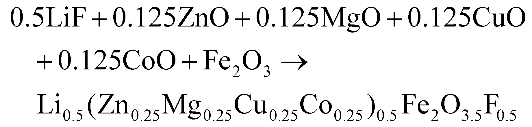
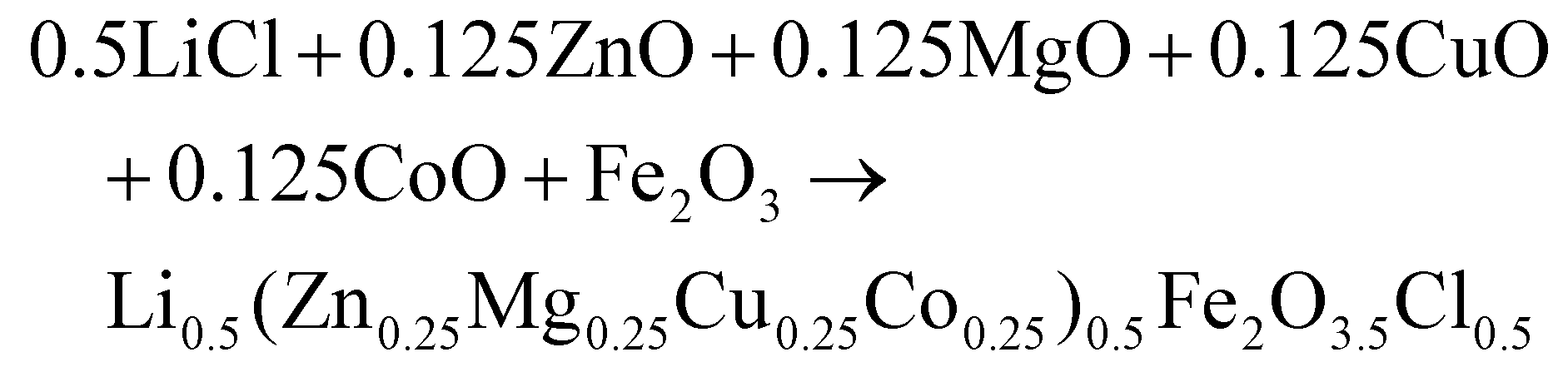
(Zn0.25Mg0.25Co0.25Cu0.25)Fe2O4 (HEOFe), Li0.5(Zn0.25Mg0.25Co0.25Cu0.25)0.5Fe2O3.5F0.5 (LiHEOFeF) and Li0.5(Zn0.25Mg0.25Co0.25Cu0.25)0.5Fe2O3.5Cl0.5 (LiHEOFeCl) were prepared by combination of ball milling and heat treatment. In the first step, a stoichiometric ratio of precursors zinc oxide (ZnO, 99.99% Aldrich), copper oxide (CuO, 99.99% Acros Organics), magnesium oxide (MgO, 99.99%, Acros Organics), iron oxide (α-Fe2O3, 99.9%; Alfa Aesar) and lithium chloride (LiCl, 98%, Acros Organics) or lithium fluoride (LiF, 99.9%, Acros Organics) were used. The cobalt oxide CoO precursor was prepared by thermal decomposition of cobalt hydroxide (Co(OH)2, 95% Acros Organics) at 180 °C in a vacuum. The mixture of precursors (see eqn (2)–(4)) was milled at 600 rpm for 390 minutes in a planetary ball mill Pulverisette 7 premium line (Fritsch). A milling chamber (80 cm3 in volume) and balls (10 mm in diameter) made of tungsten carbide (WC) were used. The ball-to-powder weight ratio was 30![[thin space (1/6-em)]](https://www.rsc.org/images/entities/char_2009.gif) :1. Milling was carried out in an argon atmosphere.
:1. Milling was carried out in an argon atmosphere.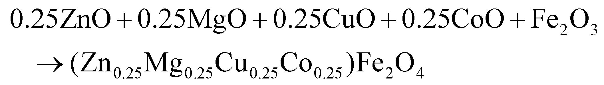 | (2) |
 | (3) |
 | (4) |
In the second step, the mechanically activated mixtures were calcined at 600 °C in an argon atmosphere for 2 h.
2.2 Structure determination
XRPD patterns were obtained using a D8 Advance diffractometer (Bruker) operating with Cu Kα radiation in the Bragg–Brentano configuration. The generator was set up at 40 kV and 40 mA and data were recorded in the range of 20 to 80° 2θ. The ICSD24 database was applied for the assignment of phases. Lattice parameters were determined by the Le Bail method in the space group Fd![[3 with combining macron]](https://www.rsc.org/images/entities/char_0033_0304.gif) m using the FullProf program25 with the application of regular pseudo-Voigt function parameters.
m using the FullProf program25 with the application of regular pseudo-Voigt function parameters.
The microstructure and morphology of the synthesized powders were investigated by (S)TEM (JEOL JEM-2100F), coupled with the Energy dispersive X-ray spectrometer (EDS) (Oxford Instruments). The sample was crushed in a mortar, dispersed in ethanol, and fixed on a copper-supported carbon grid. ImageJ software26 was used to evaluate the particle size distribution from the (S)TEM micrographs.
The elemental composition was investigated by Atomic absorption spectroscopy AAS (Varian 240RS/240Z). Before the AAS measurement, the powdered samples were dissolved in aqua regia, filtered, and diluted.
57Fe Mössbauer spectra were obtained in transmission geometry at room temperature. The 57Co isotope in the Rh matrix was used as the γ-ray source. Mössbauer data were fitted using the spectral analysis software “Recoil”.27 The Voigt-based fitting method was applied for all spectra. The experimental data were analyzed using a fitting procedure that considers hyperfine field distribution for the octahedrally coordinated ferric cations, Fe3+[Oh]. This results in the asymmetric broadening of the Fe3+[Oh] subspectrum arising from the different possible nearest-neighbor (Td)-site configurations via the supertransfer mechanism in magnetic spinels.28 In contrast, the Fe3+(Td) subspectrum reflects the presence of a narrower field distribution in agreement with the usually smaller (Td)-site supertransferred hyperfine field.29 The derived isomer shifts (IS) are normalized to the IS of α-Fe.
XPS was performed on an ESCALAB MkII, VG Scientific (now Thermo Fisher Scientific) to analyze the elemental composition of the surface and oxidation states of the metal ions. Measurements were conducted at room temperature under 5 × 10⁻⁹ mbar. A twin anode MgKα/AlKα X-ray source was used with excitation energies of 1253.6/1486.6 eV, respectively. The spectra were recorded at the total instrumental resolution (as it was measured with the FWHM of the Ag 3d5/2 photoemission line) of 1.06 and 1.18 eV for MgKα and AlKα excitation sources, respectively. The binding energies of all the elements were calibrated relative to C 1s at 285.0 eV. The processing of the measured spectra included the subtraction of X-ray satellites and a Shirley-type background.30 The peak positions and areas were determined by a symmetrical Voight-based curve fitting.
2.3 Electrode preparation
The respective electrode material (HEOFe, LiHEOFeCl, or LiHEOFeF) was mixed with conductive carbon black C65 (Timcal) and a 2% aqueous solution of carboxymethylcellulose (CMC from Sigma). The mass ratio of the HEO-containing active material to C65 and CMC was 7:2:1. The mixture was then diluted with deionized water to a consistency of viscous paste and coated by doctor-blading on Al foil. After drying in air at ambient temperature and subsequently at 100 °C in a vacuum overnight, the coated Al foil was cut into disc electrodes of 15 mm in diameter. The electrodes were stored in a glove box with an argon atmosphere.
2.4 Coin cell preparation
Coin cells were assembled with a cathode described above, a Li-foil anode (14 mm in diameter), a glass microfiber separator (Whatman), and 20 μL of electrolyte solution. The electrolyte solution consisted of 1 M LiPF6 in ethylene carbonate/dimethyl carbonate (1:1 by volume). Electrolyte solutions contained 8–12 ppm H2O as determined by Karl Fischer coulometric titration (Mettler Toledo). Electrolytes and solvents were of standard quality (p.a. or electrochemical grade) purchased from Aldrich or Merck. The electrolyte solution for Raman spectroelectrochemical measurement consisted of 1 M LiClO4 in ethylene carbonate/dimethyl carbonate (1:1 by volume). Figure S1 (ESI†) depicts the scheme of the coin cell for Raman spectroelectrochemistry. The cell was equipped with a glass window to the cathode for in situ spectral measurement.
2.5 Electrochemical characterization
Cyclic voltammetry measurements were carried out with an Autolab 302N potentiostat (Metrohm) controlled by Nova SW in a potential window of 0.65 V/3.0 V vs. Li+/Li with a scan rate of 50, 20, 10, 5, 2, 1, 0.5, 0.2, and 0.1 mV s−1. All potentials in this study are referred to the Li+/Li electrode. Galvanostatic chronopotentiometry at 1C was measured in 2032 coin-type test cells by the Neware Battery Testing System controlled by BTS 7.6 SW. Electrochemical impedance spectra (EIS) of the particular coin cell were obtained after cyclic voltammetry measurements, then after the 50th and 100th galvanostatic cycle by the FRA2 module of Autolab 302N. EIS was investigated over a frequency range from 100 kHz to 0.1 Hz (modulation amplitude 10 mV) at 2.4 V vs. Li+/Li (which is near the open-circuit potential). Before each EIS measurement, the potential was equilibrated at 2.4 V for 1 min. Spectra were evaluated using the Zview 4.0 (Scribner) software by fitting to a Randles-type circuit, in which Rs is the serial resistance and RCT (the charge-transfer resistance) is parallel to the constant phase element (CPE) to account for non-ideal capacitive behavior of the cell. The circuit is completed by the Warburg impedance ZW element for modeling the mass transport effects at lower frequencies.31,32 However, in contrast to the cited works, in which the impedances were normalized to the electrode area, we present now the spectra normalized to the mass of the active electrode material.33 Alternative normalization [to the physical (BET) areas] will give a similar result – the actual surface areas are all near 4 m2 g−1 (ref. 23). Raman spectra were obtained on a MicroRaman system (LabRAM HR spectrometer, Horiba Jobin–Yvon) interfaced to an Olympus BX microscope. The spectra were excited with a He–Ne laser, 633 nm. The Raman spectrometer was calibrated using the F1g line of Si at 520.2 cm−1. In situ Raman spectra were obtained during chronoamperometry in a quasi-equilibrium state, which was attained after 2 min of arresting the electrode potential at the selected value. Chronoamperometry was carried out with Autolab PGSTAT30 apparatus controlled by Nova SW in the potential window of 3.0 V–0.7 V vs. Li+/Li.3 Results and discussion
3.1 Structural and morphological properties
Fig. 1 shows the XRPD patterns of the as-prepared samples. They confirm the spinel-based phase with a cubic structure (Fdm), without detectable impurities. A slight shift of the diffraction peaks for LiHEOFeF and LiHEOFeCl to the higher angular positions is observed (Fig. 1, inset). This shift indicates the incorporation of lithium and fluoride/chloride ions into the spinel lattice. As further summarized in Table 1, the calculated lattice parameters decrease with the incorporation of lithium and halide ions, which is reasonable considering the difference in the ionic radii of the particular elements.34 The mean crystallite sizes of the studied samples, determined from Scherrer's equation, are from 50 to 70 nm. The morphology and particle size distribution were further investigated by (S)TEM. Fig. 2 shows the representative micrographs of the synthesized samples. They consist of agglomerated particles with a size distribution ranging from 100 to 200 nm, except for LiHEOFeF characterized by bigger particles. Approximately 100 particles were analyzed to determine the average crystallite size D (listed in Table 1). The average particle size determined by (S)TEM analysis is higher than that from XRPD. It is attributed to the agglomeration of particles. Moreover, the HR-TEM images show lattice fringes characteristic for the particular crystallographic planes (twenty atomic planes were analyzed to determine the average value). The observed values are in good agreement with those determined from the XRPD data according to the following formula: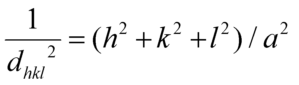 | (5) |
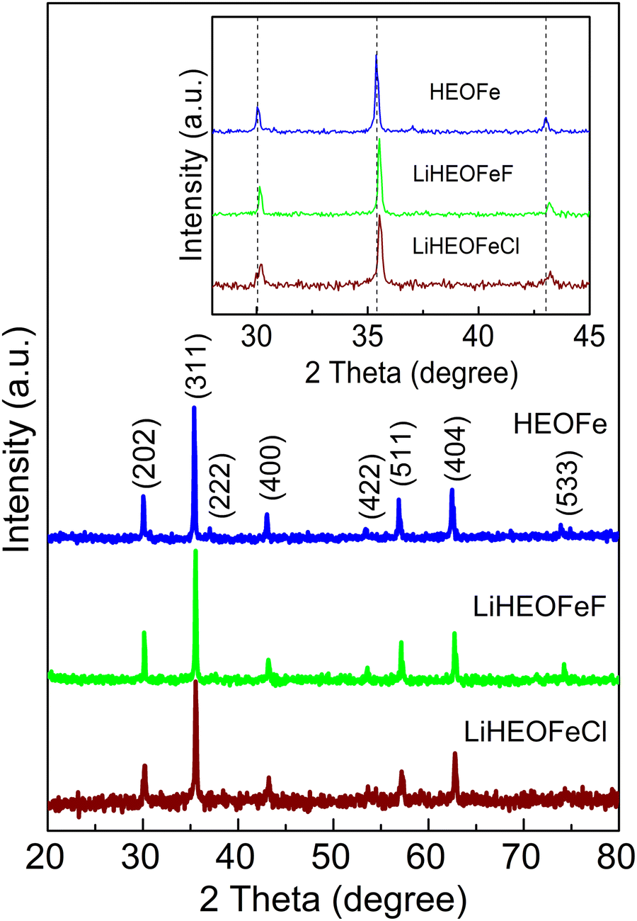 | ||
| Fig. 1 XRPD patterns of HEOFe, LiHEOFeF, and LiHEOFeCl. The inset is a zoomed image to accent the shift of diffraction peaks by the structure modification. Vertical lines are guides to the eye. | ||
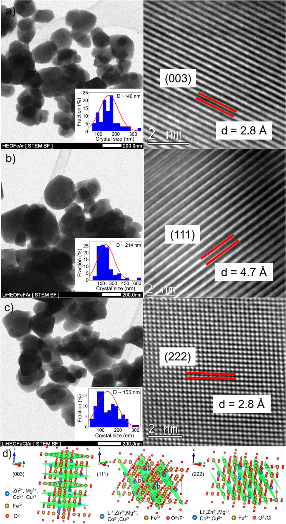 | ||
| Fig. 2 (S)TEM and HR-TEM micrographs of (a) HEOFe, (b) LiHEOFeF, and (c) LiHEOFeCl synthesized samples. Insets show the particle size distribution. Interplanar distances, d, correspond to those determined from eqn (5). (d) Idealized spinel structure of the investigated samples. Particular crystal planes for HEOFe (003), LiHEOFeF (111), and LiHEOFeCl (222) are highlighted. | ||
| Sample | Lattice parameter, a (Å) | Interplanar distance, d observed (Å) | Interplanar distance, d calculated (Å) | Crystallite size, D XRD (nm) | Crystallite size, D TEM (nm) |
|---|---|---|---|---|---|
| HEOFe | 8.4008(9) | 2.8 for (hkl = 003) | 2.8 for (hkl = 003) | 54 | 140 |
| LiHEOFeF | 8.3662(1) | 4.7 for (hkl = 111) | 4.8 for (hkl = 111) | 53 | 214 |
| LiHEOFeCl | 8.3690(4) | 2.8 for (hkl = 222) | 2.8 for (hkl = 222) | 65 | 155 |
EDS mapping of the particular elements Zn, Mg, Cu, Co, Fe, O, F, and Cl reveals their homogeneous distribution (Fig. 3). Contamination attributed to the abrasion during the milling process was below the detection limit of EDS (0.4 at% W). Even though, according to our recent experience,30 the low concentration of tungsten has an insignificant effect on the electrochemical properties of oxide-based anodes. As listed in Table 2, the final chemical composition of the synthesized spinels is quasi-equimolar and the average elemental composition determined by AAS is close to the nominal composition.
 | ||
| Fig. 3 (S)TEM micrograph of the synthesized (a) HEOFe, (b) LiHEOFeF, and (c) LiHEOFeCl samples with the corresponding elemental maps determined by EDS. | ||
| HEOFe | Zn/Fe | Mg/Fe | Co/Fe | Cu/Fe | Li/Fe |
|---|---|---|---|---|---|
| Expected | 0.1250 | 0.1250 | 0.1250 | 0.1250 | — |
| Measured | 0.1475 | 0.1350 | 0.1375 | 0.1238 | — |
| LiHEOFeF | |||||
| Expected | 0.0625 | 0.0625 | 0.0625 | 0.0625 | 0.2500 |
| Measured | 0.0770 | 0.0702 | 0.0690 | 0.0616 | 0.1931 |
| LiHEOFeCl | |||||
| Expected | 0.0625 | 0.0625 | 0.0625 | 0.0625 | 0.2500 |
| Measured | 0.0575 | 0.0560 | 0.0628 | 0.0538 | 0.2292 |
To address the local structural arrangement of the as-prepared materials, the samples were investigated by 57Fe Mössbauer spectroscopy. This method provides information on the chemical (valence) and magnetic states of the constituent iron ions including their local coordination and oxygen polyhedral distortions.35 It is known that spinel ferrites with the general formula M1M22O4 (M1 and M2 are divalent and trivalent metal cations, respectively) exhibit complex disordering phenomena involving the redistribution of cations over the sites of tetrahedral (Td) and octahedral [Oh] coordination provided by the spinel structure.36–39 To emphasize the site occupancy at the atomic level, the structural formula of these materials may be written as (M11−λM2λ)[M1λM22−λ]O4, where the parentheses and square brackets denote (Td) and [Oh] sites, respectively. The symbol λ represents the so-called degree of inversion defined as the fraction of the (Td) sites occupied by trivalent (M23+) cations. It varies from λ = 0 (normal spinel) to λ = 1 (fully inverse spinel). The value of λ = 2/3 corresponds to the random arrangement of cations. A non-equilibrium cation distribution has been evidenced in spinels prepared by various synthesis routes.40–44
Fig. 4 shows the room-temperature 57Fe Mössbauer spectra of HEOFe, LiHEOFeF, and LiHEOFeCl. The spectra of all investigated samples are well-fitted using two overlapping sextets corresponding to Fe3+ ions located on both (Td) and [Oh] sites provided by the spinel ferrite structure. Table 3 presents the hyperfine parameters of (Td)- and [Oh]-site ferric ions in the investigated materials. From the intensities of spectral components, it is revealed that Fe3+ cations in the HEOFe sample incline to the random distribution over tetrahedral and octahedral positions (I(Td)/I[Oh] ∼ 33/67). As it is evident from the quantitative analysis of 57Fe Mössbauer spectra, the presence of Li and F or Cl ions in the structures of the LiHEOFeF and LiHEOFeCl does not influence the redistribution of Fe3+ cations and results in their preferred octahedral coordination (I(Td)/I[Oh] ∼ 34/66 for LiHEOFeF and I(Td)/I[Oh] ∼ 34/66 for LiHEOFeCl; see Table 3). It should be emphasized that the presented values of the intensities of Mössbauer subspectra reflect only the distribution of Fe3+. The estimation of the degree of inversion for the HEOFe, LiHEOFeF, and LiHEOFeCl samples is not possible, because the distribution of other constituent cations among (Td) and [Oh] sites in the spinel structures is unknown.
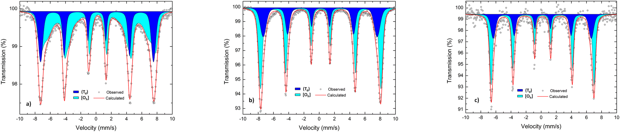 | ||
| Fig. 4 The room-temperature 57Fe Mössbauer spectra of (a) HEOFe, (b) LiHEOFeF, and (c) LiHEOFeCl. The dark blue and light blue spectra correspond to tetrahedrally (Td) and octahedrally [Oh] coordinated iron cations, respectively. | ||
| Sample | Spectral component | IS (mm s−1) | B hf (T) | I (%) |
|---|---|---|---|---|
| HEOFe | (Td) (dark blue) | 0.12(3) | 45.9(1) | 32.9(5) |
| [Oh] (light blue) | 0.26(4) | 41.1(9) | 67.1(5) | |
| LiHEOFeF | (Td) (dark blue) | 0.15(6) | 46.3(1) | 34.4(6) |
| [Oh] (light blue) | 0.18(8) | 48.9(4) | 65.6(3) | |
| LiHEOFeCl | (Td) (dark blue) | 0.16(8) | 40.2(8) | 33.5(1) |
| [Oh] (light blue) | 0.19(4) | 42.2(8) | 66.5(1) |
Fig. 5a–h show the XPS spectra (measured with AlKα excitation, see Experimental) of Zn 2p, Mg 1s, Co 2p1/2, Cu 2p3/2, Fe 2p, O 1s, F 1s, and Cl 2p for the samples HEOFe, LiHEOFeF, and LiHEOFeCl, respectively. Fig. 5a compares the Zn2p energy range of the samples. For all three samples, the shape of the line is identical with a binding energy of 1021.2 eV, indicating a Zn oxidation state of Zn2+.45,46Fig. 5b presents the Mg 1s photoelectron lines. Dashed lines indicate the positions of photoemission lines of Mg0 (1303.0 eV) and Mg2+ (1304.3 eV) reported in the literature.47 Variations in the line shape suggest Mg–F bonding in LiHEOFeF and possible Mg–O and Mg–Mg bonding in all three samples. In LiHEOFeCl, the line shape is influenced by the Auger peak of chlorine (ClKMM).
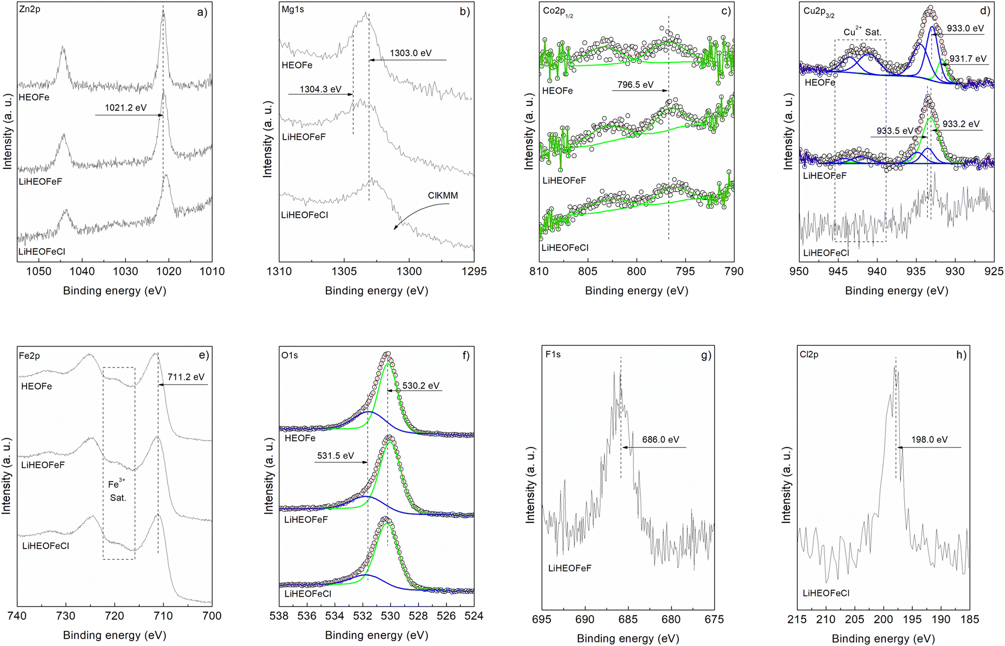 | ||
| Fig. 5 High-resolution XPS spectra of the HEOFe, LiHEOFeF, and LiHEOFeCl compounds showing the signals corresponding to (a) Zn 2p, (b) Mg 1s, (c) Co 2p1/2, (d) Cu 2p3/2, (e) Fe 2p, (f) O 1s, (g) F 1s and (h) Cl 2p. | ||
The Co 2p1/2 spectra in Fig. 5c confirm the presence of Co2+ with a peak at 796.5 eV binding energy, accompanied by an intense 3d → 4s “shake-up” satellite at 802.5 eV.45,48Fig. 5d shows the Cu 2p3/2 signal. The satellite structure in the 938–946 eV range indicates a Cu oxidation state of Cu2+.45,49,50 Curve fitting suggests Cu+/Cu2+ ratios of 0.4 and 4.1 for HEOFe and LiHEOFeF, respectively. The noisy spectrum of LiHEOFeCl complicates the analysis, but a Cu2+ oxidation state is likely. Thus, the lithiated samples stabilize Cu+ ions on the surface, whereas Cu2+ predominates in HEOFe. It is interesting to note two different chemical shifts for Cu2+. The Fe 2p core level spectra in Fig. 5e show a binding energy of 711.2 eV with a satellite structure at 716–722 eV, typical of Fe3+ in agreement with our Mössbauer spectra.51 The O 1s spectra in Fig. 5f were fitted into two peaks at 530.2 eV and 531.5 eV, corresponding to metal–oxide bonds and defect sites with low oxygen coordination, respectively.19,45 The defect sites with low oxygen coordination to metal–oxide ratios are 0.45, 0.29, and 0.22 for HEOFe, LiHEOFeF, and LiHEOFeCl, respectively, indicating that adding lithium, chloride, and fluoride reduces defect sites, with the lowest value for LiHEOFeCl. Fig. 5g and h show the binding energies of F 1s (686.0 eV) and Cl 2p (198.0 eV), respectively, corresponding to metal-fluoride and metal-chloride bonds.19,52
3.2 Electrochemical properties
The electrochemical performance of HEOFe, LiHEOFeCl, and LiHEOFeF in 2032-coin cells was evaluated by cyclic voltammetry of Li insertion in the potential window of 0.65 V/3.0 V vs. Li+/Li at the scan rate of 50, 20, 10, 5, 2, 1, 0.5, 0.2 and 0.1 mV s−1 and by galvanostatic chronopotentiometry at 1C. In addition, each cell was evaluated by electrochemical impedance spectroscopy after cyclic voltammetry and then after 50 and 100 cycles of galvanostatic charging/discharging. Fig. 6a shows the cyclic voltammograms of HEOFe, LiHEOFeCl, and LiHEOFeF. All three cyclic voltammograms contain one reduction and one main oxidation peak at 1.0 V and 1.7 V, respectively. The charge capacities calculated from the oxidation branch of the cyclic voltammogram are 450, 694, and 593 mA h g−1 for HEOFe, LiHEOFeCl, and LiHEOFeF, respectively. Such a high charging capacity speaks for a conversion reaction of lithiation for all three high-entropy compounds with a spinel structure, although the conversion mechanism is mainly suggested for high-entropy compounds with a rock salt structure with less space for Li accommodation.3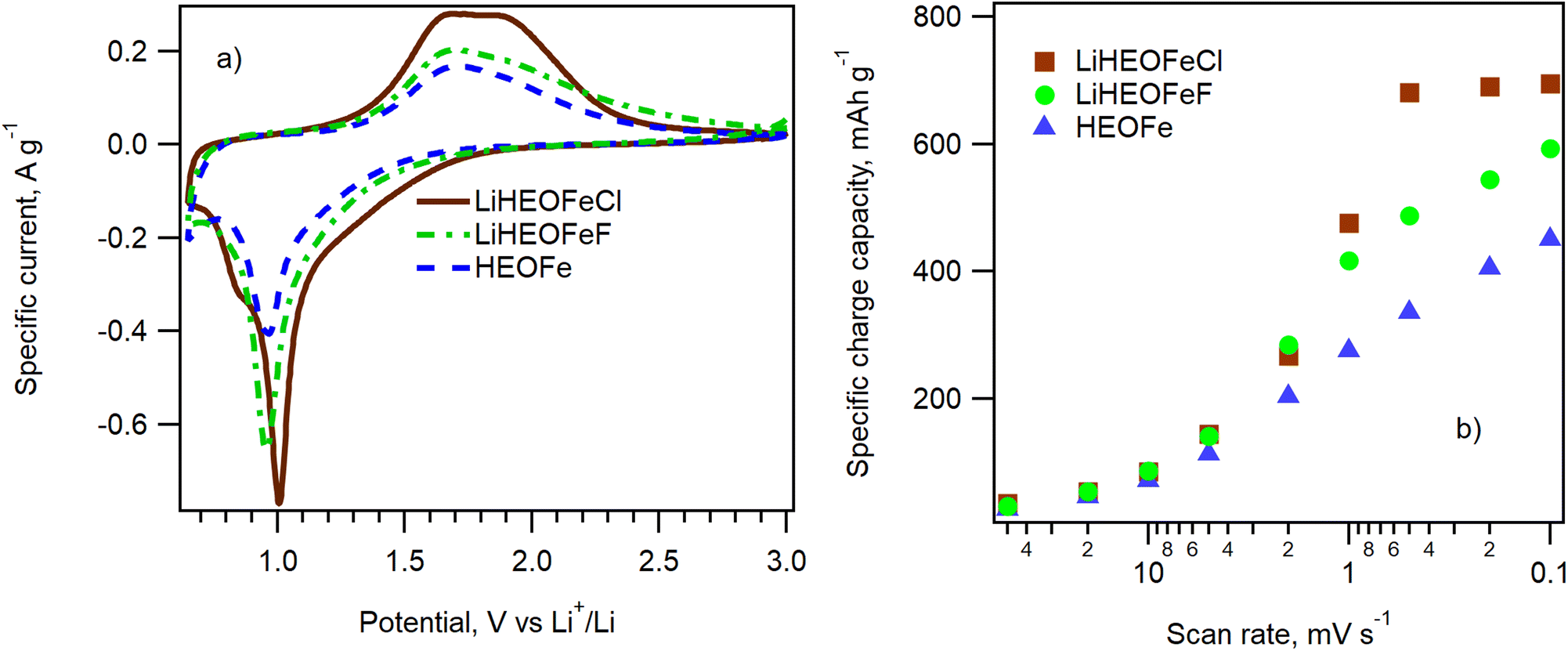 | ||
| Fig. 6 (a) Cyclic voltammograms measured on 2032-coin cells containing LiHEOFeCl, LiHEOFeF, and HEOFe with a scan rate of 0.1 mV s−1. (b) The scan-rate dependence of the charge capacities calculated from the discharge branch of the cyclic voltammogram on the scan rate for HEOFe (blue triangles), LiHEOFeCl (brown squares), and LiHEOFeF (green circles). | ||
Fig. 6b shows the dependence of the charge capacity calculated from the discharge (oxidation) branch of the cyclic voltammogram on the scan rate. The corresponding cyclic voltammograms are presented in Fig. S2.† Whereas LiHEOFeCl already reaches its maximum charge capacity at the scan rate of 0.5 mV s−1, the charge capacities of both HEOFe and LiHEOFeF exhibit a gradual increase with the decreasing scan rate, which evidences a slower conversion reaction. This effect is most probably caused by different particle sizes of the tested materials. The lithiation of high-entropy oxides is a complex process involving a conversion reaction between divalent metals in the structure with Li.3 This conversion reaction can be accelerated by increasing the interfacial area where the reaction occurs. Consequently, smaller particles with a higher surface-to-volume ratio are beneficial in promoting this process. Although the average crystallite size D((S)TEM) of HEOFe is slightly smaller than that of LiHEOFeCl (140 nm vs. 155 nm) (Fig. 2), the size distribution of the latter exhibits its maximum for particles with less than 100 nm in diameter. In contrast, the maximum of the HEOFe particle size distribution lies between 100 and 200 nm.
After cyclic voltammetry, the electrochemical impedance spectrum of a particular coin cell was recorded. Then the performance of all three materials during long-term cycling was evaluated by galvanostatic chronopotentiometry at the 1C charging/discharging rate. In addition, the electrochemical impedance spectrum was measured after the 50th and 100th cycles of charging/discharging. Fig. 7 shows the course of the galvanostatic curve for all three materials together with the calculated coulombic efficiency. Due to the interruption of galvanostatic measurements for all samples after the 50th cycle (for electrochemical impedance spectroscopy measurement) the coulombic efficiency curves show a small discontinuity. All the materials exhibit charge capacity decay, which is most pronounced for LiHEOFeCl. This capacity decay is typical of conversion electrode materials, which often show substantial capacity degradation at high currents due to kinetic limitations of the diffusion-driven processes during de-lithiation.3
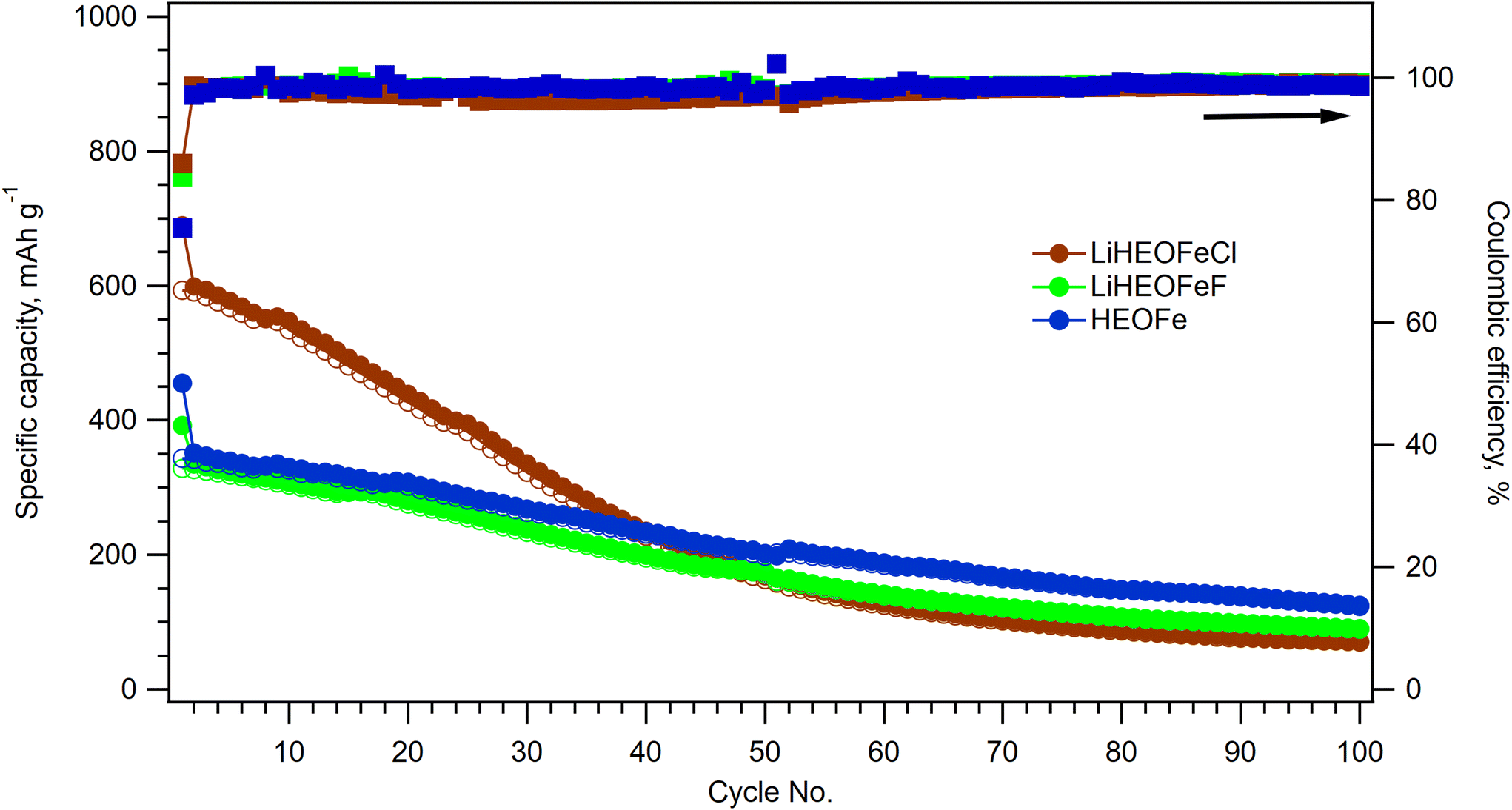 | ||
| Fig. 7 Galvanostatic chronopotentiometry at 1C rate for HEOFe (blue circles), LiHEOFeCl (brown circles), and LiHEOFeF (green circles). The charge capacity within charging is marked with full circles and the charging capacity within discharging with empty circles. The corresponding coulombic efficiencies for HEOFe, LiHEOFeCl, and LiHEOFeF are depicted by squares of the same color coding. | ||
The charge capacity is stabilized after 50 cycles at ca. 200 mA h g−1 for all the materials. Since the battery capacity decay is commonly accompanied by irreversible changes in the electrode materials, Raman spectroelectrochemistry on the LiHEOFeF sample (with the most uniform particle size distribution) was conducted to reveal morphology changes during charging/discharging. The coin cell equipped with a glass window near the LiHEOFeF electrode was assembled for in situ Raman spectroelectrochemical analysis. The coin cell open circuit potential was 1.75 V before measurement. Chronoamperometry was applied to the freshly prepared coin cell in the potential range from 3 V to 0.7 V vs. Li+/Li. Fig. 8 shows the Raman spectra of the electrode material recorded for each potential step during the lithiation (Fig. 8a) or de-lithiation (Fig. 8b). The reference Raman spectra of pristine LiHEOFeF and carbon C65 are also shown in Fig. 8a (red line) and (Fig. 8b) (blue line), respectively. The Raman features of LiHEOFeF disappear during electrochemical charging and only the carbon additive C65 and electrolyte are seen at a potential of 0.7 V (Fig. 8a). These data indicate that the structural disruption and changes of LiHEOFeF during charging are not associated with any new Raman modes. Fig. S3 (ESI†) shows current fluctuations occurring in the potential range around 2 V–1.6 V. These fluctuations are associated with the disappearance and rediscovery of Raman features of LiHEOFeF during charging in the discussed potential range (Fig. 8a). This behavior can be attributed to the first cycle on a freshly prepared electrode, where the electrode response is inhomogeneous, and the solid/electrolyte interphase is formed. The discharging process from 0.7 V to 3 V leads to gradual recovery of the LiHEOFeF Raman features (Fig. 8b). The spectra at 2 V and 2.8 V in (Fig. 8b) were collected at two different places of the cathode. The different rate of discharging in different places at an electrode is observed. Besides the inhomogeneity of the amount of the LiHEOFeF material, the reason for this different recovery rate can be the different particle sizes in both places (see the particle size distribution in Fig. 2). However, the spectrum at 3 V is obtained in the identical place of the cathode as the spectrum at 2.8 V and the LiHEOFeF Raman feature recovery is confirmed.
 | ||
| Fig. 8
In situ Raman spectroelectrochemical analysis of coin cells with the LiHEOFeF cathode and 1M LiClO4 in ethylene carbonate/dimethyl carbonate (1:1 by volume) as the electrolyte solution. (a) Charging of the coin cell from 3 V to 0.7 V vs. Li+/Li. The Raman spectrum of blank LiHEOFeF is also shown (red line). The label rep stands for repeated measurement at 1.8 V. (b) Discharging of coin cells from 0.7 V to 3 V vs. Li+/Li. The Raman spectrum of the blank C65 additive is also shown (blue line). Spectra are offset, but the intensity scale is identical for all plots. | ||
The data show good reversibility of the system during the first charging/discharging cycle.
The impedance spectra shown in Fig. 9 confirm the high electrochemical activity of freshly assembled cells with a LiHEOFeCl-based cathode. For easy comparison of individual electrodes, the spectra are normalized to the mass of the active material.33 The EIS fitting provided charge-transfer resistances of 5.36 mΩ g, 33.1 mΩ g, and 3.36 mΩ g for the cells with HEOFe, LiHEOFeF and LiHEOFeCl, respectively. Galvanostatic cycling causes a decrease of RCT of both high-entropy oxyhalides, which is reminiscent of the similar behavior of the LiHEOFeCl-based cathode in an electrolyte standardly used for Li–sulfur cells (LiTFSI + LiNO3 in 1.3 dioxolane/1,2-dimethoxyethane).23 In contrast, the cycling of HEOFe leads to a small enhancement of RCT, which is accompanied by a marked improvement of the serial resistance, Rs. At this stage of our research, we have no persuasive explanation for the difference. The mechanism of electrochemical reduction of HEOFe and the high-entropy oxyhalides can be different, which is mirrored in the specific EIS features of the former. Furthermore, the extraordinary electrochemical activity of LiHEOFeCl, observed at early stages of voltammetric and galvanostatic cycling (Fig. 6–8), is in accord with the smallest observed charge-transfer resistance of this particular material.
 | ||
| Fig. 9 Electrochemical impedance spectra of our coin cells with LiHEOFeX- and HEOFe-based cathodes. (A) Freshly assembled cells after nine formatting cycles by cyclic voltammetry. (Inset: details of the spectra measured at the high-frequency cutoff). (B) The spectra as in chart A but fitted to the equivalent circuit shown. (C) Spectra of the same cell after 50 galvanostatic charge/discharge cycles at 1C. (D) Spectra of the same cell after 100 galvanostatic charge/discharge cycles at 1C. For color coding of curves see the annotation in chart A. (E and F) Impedance spectra for freshly assembled and cycled cells (as in charts A–D, but with the HEOFe-based cathode). | ||
4. Conclusions
The phase pure high-entropy oxide (Zn0.25Mg0.25Co0.25Cu0.25)Fe2O4 (HEOFe), lithiated oxyfluoride Li0.5(Zn0.25Mg0.25Co0.25Cu0.25)0.5Fe2O3.5F0.5 (LiHEOFeF), and lithiated oxychloride Li0.5(Zn0.25Mg0.25Co0.25Cu0.25)0.5Fe2O3.5Cl0.5 (LiHEOFeCl) were prepared by combination of mechanical milling and heat treatment. X-ray powder diffraction confirmed their spinel-based cubic structure (Fdm) with an average crystallite size of 50–70 nm. The corresponding particle sizes from (S)TEM are 3–4 times larger due to the agglomeration of the crystallites. EDS mapping confirmed a homogeneous distribution of constituent elements in all the prepared samples. In addition, the average elemental composition determined by AAS is close to the nominal composition. Mössbauer spectroscopy revealed that Li and F or Cl ions do not influence the redistribution of Fe3+ cations. Photoelectron spectroscopy provided deeper insight into the electronic states of particular cations and anions.
Electrochemical measurements carried out in the 2032-coin cell with a Li-metal anode indicated voltammetric charge capacities of 450, 694, and 593 mA h g−1 for HEOFe, LiHEOFeCl, and LiHEOFeF, respectively. They exceed almost four times the theoretical capacity of classical intercalation electrodes of Li-ion batteries. The best electrochemical performance of LiHEOFeCl was ascribed to its smallest particle size enabling a faster electrochemical conversion reaction. Galvanostatic chronopotentiometry at 1C rate confirmed high initial charge capacities for all the samples but a capacity decay over 100 charging/discharging cycles. This decay was the most pronounced for the sample LiHEOFeCl with the highest initial charge capacity.
Raman spectroelectrochemical analysis of LiHEOFeF proved the reversibility of the electrochemical process for the initial charging/discharging cycles. Electrochemical impedance spectroscopy data agree with cyclic voltammetry and galvanostatic chronopotentiometry for all three samples. The initial charge transfer resistance of LiHEOFeCl exhibits the lowest value and decreases gradually during galvanostatic cycling, analogous to that of LiHEOFeF. In contrast, galvanostatic cycling causes an enhancement of the charge transfer resistance of the HEOFe sample, obviously due to the different mechanisms of the electrochemical reduction.
Author contributions
Conceptualization, M. Z., L. K., and M. F.; methodology, M. Z., M. F., and L. K.; investigation, M. Z., M. F., O. P., L. K., B. P. L., V. Š., H. K., K. L. S., and M. L.; data curation, M. Z., M. F., O. P., B. P. L., H. K., and L. K.; writing – original draft preparation, M. Z., L. K., and M. F.; writing – review and editing, M. Z., L. K., M. F., and B. P. L.; project administration, M. Z., and M. F.; funding acquisition, M. Z., M. F., H. K., O. P., and V. Š. All authors have read and agreed to the published version of the manuscript.Data availability
Data are available at the following link https://doi.org/10.5281/zenodo.13827515.Conflicts of interest
There are no conflicts to declare.Acknowledgements
We gratefully appreciate the contribution of Professor M. Senna (Keio University, Japan) towards editing the manuscript. This work was financially supported by the Ministry of Education, Youth and Sports of the Czech Republic under the project “The Energy Conversion and Storage”, funded as project No. CZ.02.01.01/00/22_008/0004617 by Programme Johannes Amos Comenius, call Excellent Research. O. P. and M. F. thank Slovak Grant Agency VEGA (2/0058/23) and Slovak Research and Development Agency APVV (DS-FR-22-0037). M. F. and H. K. also thank BAS-SAS (projects No. 2022-06 and IC-SK/02/2023-2024). V.Š. acknowledges DFG (project SE 1407/4-2).References
- R. Zhang, C. Wang, P. Zou, R. Lin, L. Ma, L. Yin, T. Li, W. Xu, H. Jia, Q. Li, S. Sainio, K. Kisslinger, S. E. Trask, S. N. Ehrlich, Y. Yang, A. M. Kiss, M. Ge, B. J. Polzin, S. J. Lee, W. Xu, Y. Ren and H. L. Xin, Nature, 2022, 610, 67–73 CrossRef CAS.
- J. W. Sturman, E. A. Baranova and Y. Abu-Lebdeh, Front. Energy Res., 2022, 10, 862551 CrossRef.
- A. Sarkar, L. Velasco, D. Wang, Q. Wang, G. Talasila, L. de Biasi, C. Kubel, T. Brezesinski, S. S. Bhattacharya, H. Hahn and B. Breitung, Nat. Commun., 2018, 9, 3400 CrossRef.
- P. B. Meisenheimer, L. D. Williams, S. H. Sung, J. Gim, P. Shafer, G. N. Kotsonis, J. P. Maria, M. Trassin, R. Hovden, E. Kioupakis and J. T. Heron, Phys. Rev. Mater., 2019, 3, 104420 CrossRef CAS.
- C. M. Rost, E. Sachet, T. Borman, A. Moballegh, E. C. Dickey, D. Hou, J. L. Jones, S. Curtarolo and J. P. Maria, Nat. Commun., 2015, 6, 8485 CrossRef CAS PubMed.
- J. W. Yeh, Jom, 2013, 65, 1759–1771 CrossRef CAS.
- A. Sarkar, B. Breitung and H. Hahn, Scr. Mater., 2020, 187, 43–48 CrossRef CAS.
- A. Sarkar, R. Djenadic, D. Wang, C. Hein, R. Kautenburger, O. Clemens and H. Hahn, J. Eur. Ceram. Soc., 2018, 38, 2318–2327 CrossRef CAS.
- T. X. Nguyen, J. Patra, C. C. Tsai, W. Y. Xuan, H. Y. T. Chen, M. S. Dyer, O. Clemens, J. Li, S. B. Majumder, J. K. Chang and J. M. Ting, Adv. Funct. Mater., 2023, 33, 2300509 CrossRef CAS.
- D. Wang, S. Jiang, C. Duan, J. Mao, Y. Dong, K. Dong, Z. Wang, S. Luo, Y. Liu and X. Qi, J. Alloys Compd., 2020, 844, 156158 CrossRef CAS.
- W. Bian, H. Li, Z. Zhao, H. Dou, X. Cheng and X. Wang, Electrochim. Acta, 2023, 447, 142157 CrossRef CAS.
- H. Chen, N. Qiu, B. Wu, Z. Yang, S. Sun and Y. Wang, RSC Adv., 2020, 10, 9736–9744 RSC.
- D. Csík, D. Zalka, K. Saksl, D. Capková and R. Džunda, J. Phys. Conf. Ser., 2022, 2382, 012003 CrossRef.
- J. Patra, T. X. Nguyen, C. C. Tsai, O. Clemens, J. Li, P. Pal, W. K. Chan, C. H. Lee, H. Y. T. Chen, J. M. Ting and J. K. Chang, Adv. Funct. Mater., 2022, 32, 2110992 CrossRef CAS.
- B. Talluri, M. L. Aparna, N. Sreenivasulu, S. S. Bhattacharya and T. Thomas, J. Energy Storage, 2021, 42, 103004 CrossRef.
- C. Triolo, M. Maisuradze, M. Li, Y. Liu, A. Ponti, G. Pagot, V. Di Noto, G. Aquilanti, N. Pinna, M. Giorgetti and S. Santangelo, Small, 2023, 19, e2304585 CrossRef PubMed.
- H.-Z. Xiang, H.-X. Xie, Y.-X. Chen, H. Zhang, A. Mao and C.-H. Zheng, J. Mater. Sci., 2021, 56, 8127–8142 CrossRef CAS.
- Y. Yin, W. B. Zhang, X. L. Zhang, M. M. Theint, J. L. Yang, Z. Q. Yang, J. J. Li, S. Liang and X. J. Ma, Dalton Trans., 2023, 52, 9005–9016 RSC.
- E. Lökçu, C. Toparli and M. Anik, ACS Appl. Mater. Interfaces, 2020, 12, 23860–23866 CrossRef.
- C. Duan, K. Tian, X. Li, D. Wang, H. Sun, R. Zheng, Z. Wang and Y. Liu, Ceram. Int., 2021, 47, 32025–32032 CrossRef CAS.
- K.-H. Tian, C.-Q. Duan, Q. Ma, X.-L. Li, Z.-Y. Wang, H.-Y. Sun, S.-H. Luo, D. Wang and Y.-G. Liu, Rare Met., 2021, 41, 1265–1275 CrossRef.
- G. Ma, Y. Zheng, F. Meng and R. Hu, Energy adv., 2023, 2, 1685–1692 RSC.
- M. Zukalová, M. Fabián, O. Porodko, M. Vinarčíková, B. Pitňa Lásková and L. Kavan, RSC Adv., 2023, 13, 17008–17016 RSC.
- Inorganic Crystal Structure Database, FIZ Karlsruhe GmbH.
- J. Rodriguez-Carvajal, Fullprof Program, ILL Grenoble, France, 2.4.2 edn, 1993 Search PubMed.
- C. A. Schneider, W. S. Rasband and K. W. Eliceiri, Nat. Methods, 2012, 9, 671–675 CrossRef CAS PubMed.
- K. Lagarec and D. G. Rancourt, Recoil-Mössbauer Spectral Analysis Software for Windows, Department of Physics, University of Ottawa, 1.02 edn, 1998 Search PubMed.
- G. A. Sawatzky, F. Van Der Woude and A. H. Morrish, Phys. Rev., 1969, 187, 747–757 CrossRef CAS.
- V. Šepelák, D. Baabe, F. J. Litterst and K. D. Becker, J. Appl. Phys., 2000, 88, 5884–5893 CrossRef.
- D. A. Shirley, Phys. Rev. B, 1972, 5, 4709–4714 CrossRef.
- M. Zukalová, M. Fabián, M. Klusáčková, M. Klementová, B. Pitňa Lásková, Z. Danková, M. Senna and L. Kavan, Electrochim. Acta, 2018, 265, 480–487 CrossRef.
- M. Senna, M. Fabián, L. Kavan, M. Zukalová, J. Briancin, E. Turianicova, P. Bottke, M. Wilkening and V. Šepelák, J. Solid State Electrochem., 2016, 20, 2673–2683 CrossRef CAS.
- H. Krýsová, M. Zlámalová, H. Tarábková, J. Jirkovský, O. Frank, M. Kohout and L. Kavan, Electrochim. Acta, 2019, 321, 134685 CrossRef.
- R. D. Shannon, Acta Crystallogr., Sect. A, 1976, 32, 751–767 CrossRef.
- V. Šepelák, A. Duvel, M. Wilkening, K. D. Becker and P. Heitjans, Chem. Soc. Rev., 2013, 42, 7507–7520 RSC.
- V. Šepelák, I. Bergmann, S. Indris, A. Feldhoff, H. Hahn, K. D. Becker, C. P. Grey and P. Heitjans, J. Mater. Chem., 2011, 21, 8332–8337 RSC.
- V. Šepelák, S. Begin-Colin and G. Le Caer, Dalton Trans., 2012, 41, 11927–11948 RSC.
- V. Šepelák, S. M. Becker, I. Bergmann, S. Indris, M. Scheuermann, A. Feldhoff, C. Kübel, M. Bruns, N. Stürzl, A. S. Ulrich, M. Ghafari, H. Hahn, C. P. Grey, K. D. Becker and P. Heitjans, J. Mater. Chem., 2012, 22, 3117–3126 RSC.
- M. Wilkening, A. Düvel, F. Preishuber-Pflügl, K. da Silva, S. Breuer, V. Šepelák and P. Heitjans, Z. Kristallogr. – Cryst. Mater., 2017, 232, 107–127 CrossRef CAS.
- Z. Ž. Lazarević, Č. Jovalekić, V. N. Ivanovski, A. Rečnik, A. Milutinović, B. Cekić and N. Ž. Romčević, J. Phys. Chem. Solids, 2014, 75, 869–877 CrossRef.
- V. G. Harris and V. Šepelák, J. Magn. Magn. Mater., 2018, 465, 603–610 CrossRef CAS.
- J. Sanchez-Marcos, E. Mazario, J. A. Rodriguez-Velamazan, E. Salas, P. Herrasti and N. Menendez, J. Alloys Compd., 2018, 739, 909–917 CrossRef CAS.
- S. Talebniya, I. Sharifi, M. R. Saeri and A. Doostmohammadi, J. Supercond. Novel Magn., 2022, 35, 899–908 CrossRef CAS.
- M. Fabián, P. Bottke, V. Girman, A. Düvel, K. L. Da Silva, M. Wilkening, H. Hahn, P. Heitjans and V. Šepelák, RSC Adv., 2015, 5, 54321–54328 RSC.
- O. Porodko, M. Fabián, H. Kolev, M. Lisnichuk, M. Zukalová, M. Vinarčíková, V. Girman, K. L. Da Silva and V. Šepelák, Z. Physiol. Chem., 2022, 236, 713–726 CrossRef CAS.
- B. Strohmeier, J. Catal., 1984, 86, 266–279 CrossRef CAS.
- S. Aksoy, Y. Caglar, S. Ilican and M. Caglar, J. Alloys Compd., 2012, 512, 171–178 CrossRef CAS.
- S. Todorova, J. L. Blin, A. Naydenov, B. Lebeau, D. Karashanova, H. Kolev, P. Gaudin, R. Velinova, L. Vidal, L. Michelin, L. Josien, D. Filkova, I. Ivanova, A. Dotzeva and K. Tenchev, Catal. Today, 2021, 361, 94–101 CrossRef CAS.
- S. Saedy, N. Hiemstra, D. Benz, H. Van Bui, M. Nolan and J. R. van Ommen, Catal. Sci. Technol., 2022, 12, 4511–4523 RSC.
- P. A. DeSario, J. J. Pietron, T. H. Brintlinger, M. McEntee, J. F. Parker, O. Baturina, R. M. Stroud and D. R. Rolison, Nanoscale, 2017, 9, 11720–11729 RSC.
- S. Gota, E. Guiot, M. Henriot and M. Gautier-Soyer, Phys. Rev. B:Condens. Matter Mater. Phys., 1999, 60, 14387–14395 CrossRef CAS.
- J. F. Moulder, W. F. Stickle, W. M. Sobol and K. D. Bomben, Handbook of X-Ray Photoelectron Spectroscopy, Perkin Elmer Corporation, 1992 Search PubMed.
Footnote |
| † Electronic supplementary information (ESI) available. See DOI: https://doi.org/10.1039/d4nr03918a |
| This journal is © The Royal Society of Chemistry 2025 |