 Open Access Article
Creative Commons Attribution 3.0 Unported Licence
Dextran stabilised hematite: a sustainable anode in aqueous electrolytes†
Sofia
Panagiotidou‡
a,
Evangelia
Vasilaki‡§
 *ab,
Nikos
Katsarakis
 c,
Dimitra
Vernardou
 *c and
Maria
Vamvakaki
 ab
ab
aDepartment of Materials Science and Engineering, University of Crete, 700 13 Heraklion, Crete, Greece. E-mail: evasilaki@iesl.forth.gr
bInstitute of Electronic Structure and Laser, Foundation for Research and Technology – Hellas, 700 13 Heraklion, Crete, Greece
cDepartment of Electrical & Computer Engineering, School of Engineering, Hellenic Mediterranean University, Heraklion, 710 04 Crete, Greece. E-mail: dvernardou@hmu.gr
First published on 13th January 2025
Abstract
During the last decades, the use of innovative hybrid materials in energy storage devices has led to notable advances in the field. However, further enhancement of their electrochemical performance faces significant challenges nowadays, imposed by the materials used in the electrodes and the electrolyte. Such problems include the high solubility of both the organic and the inorganic anode components in the electrolyte as well as the limited intrinsic electronic conductivity and substantial volume variation of the materials during cycling. The present work focuses on the fabrication of novel and sustainable anode electrodes for use in energy storage devices, utilizing cross-linked oxidized dextran (Ox-Dex) as the binder and hematite (α-Fe2O3) cubes as the active component. The ion diffusion mechanism within the anode electrode materials, as well as their cycling stability, were studied via cyclic voltammetry measurements, using Li+, Zn2+ and Al3+ aqueous electrolytes. The hybrid iron oxide electrodes exhibited the highest electrochemical performance in the Al2(SO4)3 electrolyte (3000 mA g−1), followed by ZnSO4 (2000 mA g−1) and Li2SO4 (800 mA g−1). The differences in the performance of the anodes for the three investigated electrolytes were attributed to the ionic radii of Li+, Zn2+ and Al3+, which affect the rate of ion diffusion within the material lattice exhibiting the highest diffusion coefficient of 4.64 × 10⁻⁹ cm2 s−1 in Al3+. Notably, the hybrid anodes demonstrated superior cycling performance (with the lowest variance percentage of 1.3% for hybrid compared to 38.1% for the bare in the presence of Zn2+), underlining the pivotal role of the natural binder. This was attributed to hydrogen bonding interactions, which increase the contact points between the inorganic and polymeric components, resulting in a more uniform network structure. Additionally, the cross-linking of Ox-Dex promotes stability and tolerance to the volume expansion of the electrodes. These results underscore the immense potential of the proposed hybrid electrodes in the field of energy storage.
1. Introduction
The increasing energy storage demands in modern society have brought to light certain limitations of lithium-ion batteries (LIBs), including their non-effective delivery of large amounts of power, high cost and poor safety.1,2 From this perspective, alternative battery chemistries, such as those based on Zn2+ and Al3+ multivalent ions, have appeared as attractive options.3 Zinc ion batteries (ZIBs) are of great interest, due to their low cost, environmental friendliness, acceptable energy density (80–150 W h kg−1)4 suitable for stationary and low-power applications and safety in mild aqueous electrolytes.5 The electrochemical dissolution and deposition of zinc takes place at ∼0 V vs. Zn2+/Zn, which renders the process ideal for the anodic reaction.6 In addition, ZIBs benefit from the high ionic conductivity of Zn2+ (1.57 × 10⁻³ S cm−1), achieving a much faster charge/discharge rate compared to Li+ (10−6 S cm−1),7 and the higher abundance of the element in the Earth's crust compared to Li.8 On the other hand, Al3+ stands out as a trivalent cation, being the most prevalent metal in the Earth's crust (8.1%).9 Aluminum also possesses enhanced ion diffusion and achieves improved electrochemical behavior, due to its relatively small ionic radius (R = 53.5 pm) compared to other metal ions (Zn2+: 74 pm and Li+: 76 pm).8,10–12 Finally, aluminum ion batteries are highly recyclable, and therefore more sustainable, compared to LIBs.10 While, multivalent ion batteries hold great promise, the search for suitable anode materials compatible with these electrolytes presents significant challenges. These materials encounter similar issues to lithium, particularly regarding dendrite formation and electrode volume changes.13 Zinc anodes in particular, are prone to corrosion, which can diminish the battery lifespan and performance,14 while aluminum foil anodes, undergo drastic structural degradation induced by the large volume changes during the battery reactions.15 This discrepancy occurs due to aluminum's ability to form a stable, protective oxide layer on its surface, which serves as a barrier that shields the underlying metal from further oxidation or reaction with the environment.To address these challenges, hybrid nanostructured materials that combine active materials with organic binders have been intensively studied as potential anode materials, as they offer improved performance, lower degradation, superior safety and enhanced versatility compared to the single component systems.16–19 Various materials have been evaluated for their applicability as the active components in anode electrodes, including carbon-based materials, tin alloys, antimony and phosphorus.20–22 Transition metal oxides have been also explored in hybrid materials development, for electrode fabrication, due to their high electrochemical performance, capacity reversibility during the ion charging/discharging processes and straight-forward synthetic routes.23–25 Among them, hematite, Fe2O3, stands out as a highly promising candidate, owing to its remarkable attributes that include high theoretical capacity (1007 mA h g−1), stability at ambient conditions, natural abundance, low cost, and environmentally friendly nature.26–28 The organic binder constitutes the second key component in hybrid anode electrodes, as it has been recognized to affect the aging, irreversible capacity loss and coulombic efficiency of the battery.29 The most widely studied binders refer to conventional synthetic polymers, mainly polyvinylidene fluoride (PVDF), but also polyacrylic acid and its sodium or lithium salts, polyimide, polyvinylpyrrolidone, polyacrylonitrile and polyvinyl alcohol.30–34 However, growing environmental concerns on synthetic polymers have lately shifted the attention to natural and aqueous-based binders as greener alternatives. Polysaccharides, such as carboxymethyl cellulose, chitosan, gum arabic and alginates, are attractive candidates, due to their affordability, water solubility and environmentally friendly nature.30,33,35–37 Moreover, these natural polymers possess numerous functional groups that can interact with the active material, or be exploited in cross-linking reactions towards the formation of hyperbranched networks. As a result, hybrid electrodes with excellent mechanical properties are fabricated, capable of buffering the volume fluctuations that occur during battery cycling, which lead in irreversible slipping of the active material and structural fractures between the active particles, and eventually in poor battery stability.38–40
In contrast to the aforementioned polysaccharides, dextran, a water-soluble, natural glucan, rich in hydroxyl groups, has received negligible attention. Recently, hybrid anode electrodes combining silicon and graphite materials with dextran were reported to exhibit high coulombic efficiency and good cycling in Li-ion cells, a performance that was found superior to the conventional PVDF and poly(acrylic acid sodium salt) binder.41 In another interesting work, a modified analogue of dextran, lithium dextran sulfate, was used as a protective binder in Li-ion batteries. The lithiated polysaccharide was found to dynamically bind onto both a Cu foil current collector and metallic Li, through its chemically introduced –O-SO3− functional groups, preventing the formation of dendrites and stabilizing the electrode interface, again surpassing the inferior stability of the conventional PVDF binder.42 Nevertheless, in all these reports non-aqueous, carbonate-based electrolytes were employed, which should be replaced with aqueous analogues towards more advanced, green and sustainable energy storage systems of lower cost and higher safety.43 This future prospect, however, limits the applicability of natural, hydrophilic polymers, because they are soluble in the aqueous battery electrolytes, a characteristic which deteriorates the stability and performance of the electrode via the dissolution of the binder and the loss of the active material in the electrolyte.31
In the present study, we aim to develop and evaluate high performance and environmentally friendly hybrid anode electrodes in aqueous metal ion electrolytes. Oxidized dextran (Ox-Dex), a chemically modified analogue of the natural polysacharide, was employed as the polymeric binder to immobilize hematite pseudocube particles as the active material. The cross-linking of Ox-Dex via hydrazone bonds, served the essential purpose of preventing the dissolution of the binder and thus the loss of the active material in the aqueous electrolyte, while more importantly it ensured the structural integrity of the hybrid electrode during the intercalation/de-intercalation processes due to the elasticity of the polymer and the dynamic nature of the hydrazone bonds. The performance and stability of the hybrid electrodes were also promoted by hydrogen bonding interactions, which can be reversibly disrupted and reformed during cycling, between the remaining, non-oxidized hydroxyl groups of the natural polymer and the surface functionalities of the hematite particles. A holistically green, water-based approach was employed during all steps, from the synthesis or chemical modification of the precursors, the electrode fabrication and electrochemical evaluation of the anodes. Lithium sulfate (Li2(SO4)), zinc sulfate (ZnSO4) and aluminum sulfate (Al2(SO4)3) were employed as sustainable aqueous electrolytes, while the diffusion mechanism of the Li+, Zn2+, and Al3+ ions within the hybrid material lattice was elucidated by cyclic voltammetry measurements, performed at various scan numbers and rates. The stability of the prepared hybrid anodes was also verified via physicochemical and morphological analyses in Zn2+. These analyses highlighted their promising electrochemical performance in terms of stability and diffusion coefficient, compared to values reported in the literature for the specific chemistry. Moreover, the results affirmed the preservation of their morphology and structure after continuous intercalation/de-intercalation cycles.
2. Materials and methods
2.1 Materials
Dextran T-40 (MW = 40 kDa) was purchased from Serva. Methyl orange (dye content 85%) was supplied from Fluka. Sodium metaperiodate (ACS reagent, 99%), hydroxylamine hydrochloride (ACS reagent, 98%), ferric chloride anhydrous (ACS reagent, 99.9%), sodium sulfate anhydrous (ACS reagent, ≥99%), sodium hydroxide anhydrous (ACS reagent grade, ≥98%, pellets), adipic acid dihydrazide (AAD) (≥98%), lithium sulfate (≥98%), aluminum sulfate hydrate (97%) and zinc sulfate heptahydrate (98%) were supplied from Sigma-Aldrich. All chemicals were used as received. Milli–Q water with a resistivity of 18.2 MΩ cm at 298 K was obtained from a Millipore apparatus and was used for all experiments.2.2 Synthesis of the α-Fe2O3 particles
α-Fe2O3 particles were synthesized using a protocol reported by Sugimoto et al.44 In specific, 100 mL of a 2 M FeCl3 solution were added to 90 mL of a 6 M NaOH solution under stirring. Next, the solution was transferred into a sealed Pyrex bottle and was placed in an oven thermostated at 100 °C, and was allowed to age for 8 d. The red product was collected by filtration, washed three times with ethanol and Milli–Q water, followed by drying overnight under vacuum.2.3 Oxidation of dextran (Ox-Dex)
The oxidation of dextran was carried out targeting a 30% degree of oxidation, taking into account that the quantitative oxidation of the dextran hydroxyl groups requires a 2![[thin space (1/6-em)]](https://www.rsc.org/images/entities/char_2009.gif) :
:![[thin space (1/6-em)]](https://www.rsc.org/images/entities/char_2009.gif) 1 molar ratio of NaIO4 over the saccharide repeat units.45 Briefly, dextran (3.56 g, 0.022 moles) was first dissolved via stirring in 400 mL Milli–Q water. Then, 2.78 g NaIO4 (0.013 moles) were added to the dextran solution and the reaction vessel was wrapped with an aluminum foil and was left under stirring at room temperature overnight. Finally, the product was purified by dialysis against water using a dialysis membrane with a cut-off limit of 3500 Da. Finally, the aqueous Ox-Dex solution was lyophilized to afford the product as a white solid.
1 molar ratio of NaIO4 over the saccharide repeat units.45 Briefly, dextran (3.56 g, 0.022 moles) was first dissolved via stirring in 400 mL Milli–Q water. Then, 2.78 g NaIO4 (0.013 moles) were added to the dextran solution and the reaction vessel was wrapped with an aluminum foil and was left under stirring at room temperature overnight. Finally, the product was purified by dialysis against water using a dialysis membrane with a cut-off limit of 3500 Da. Finally, the aqueous Ox-Dex solution was lyophilized to afford the product as a white solid.
2.4 Preparation of the bare α-Fe2O3 electrodes
For the fabrication of the electrodes of ∼400 μm thickness, a conventional drop casting technique on Cu substrates with a surface area of 2.25 cm2, was employed. On each substrate, 0.35 g of a 4 wt% aqueous dispersion of the α-Fe2O3 particles, corresponding to ∼0.014 g active material, were drop-casted using a micropipette. The electrodes were dried under vacuum at room temperature until the complete evaporation of the solvent.2.5 Preparation of the hybrid α-Fe2O3/Ox-Dex electrodes
For the fabrication of the hybrid α-Fe2O3/Ox-Dex electrodes, 0.35 g of a 0.8 wt% aqueous solution of Ox-Dex was prepared, followed by the addition of 0.014 g α-Fe2O3, targeting a 5![[thin space (1/6-em)]](https://www.rsc.org/images/entities/char_2009.gif) :
:![[thin space (1/6-em)]](https://www.rsc.org/images/entities/char_2009.gif) 1 mass ratio of inorganic particles to the polymer binder. Next, 2.1 μL of a 100 mg mL−1 AAD cross-linker solution were added in the α-Fe2O3/Ox-Dex solution under continuous stirring. Finally, the suspension was uniformly deposited onto a Cu substrate, with a surface area of 2.25 cm2, by drop casting and was dried under vacuum at room temperature to prepare hybrid electrodes with a comparable film thickness to the bare analogues.
1 mass ratio of inorganic particles to the polymer binder. Next, 2.1 μL of a 100 mg mL−1 AAD cross-linker solution were added in the α-Fe2O3/Ox-Dex solution under continuous stirring. Finally, the suspension was uniformly deposited onto a Cu substrate, with a surface area of 2.25 cm2, by drop casting and was dried under vacuum at room temperature to prepare hybrid electrodes with a comparable film thickness to the bare analogues.
2.6 Characterization methods
2.7 Electrochemical experiments
The electrochemical performance of the samples was evaluated using an electrochemical cell with a typical tri-electrode configuration and a computer-controlled AUTOLAB potentiostat/galvanostat.47,48 Ag/AgCl and graphite were used as the reference and the counter electrodes, respectively, whereas the material under investigation was used as the working electrode, with a geometric area of 2.25 cm2, in each case. Aqueous solutions of 1 M Li2SO4, ZnSO4·7H2O and Al2(SO4)3·H2O were employed as the electrolytes, and the scan rate was kept constant at 20 mV s−1 for all electrolytes. The operating potential window for Li2SO4 was −0.75 to +0.1 V, for ZnSO4 –0.65 to +0.15 V and for Al2(SO4)3 −0.55 V to +0.25 V. Cyclic voltammograms were also obtained at scan rates of 5, 10, 20, 30, 40, 50 and 100 mV s−1 to elucidate the metal ion intercalation mechanism and estimate the diffusion coefficient of each metal. The current was expressed as specific current (A g−1) relative to the mass of the electrode material that was immersed in the electrolyte. All electrochemical tests were carried out at room temperature (25 °C).3. Results and discussion
3.1 Physicochemical and morphological characterization of Ox-Dex and of the α-Fe2O3 particles
The oxidation of dextran proceeded under mild aqueous conditions using sodium periodate as the oxidizing agent. The targeted degree of oxidation was 30% based on previous studies in our lab, which showed that at this degree of modification the polymer presented sufficient aldehyde groups that allowed its effective cross-linking to form a stable gel. Moreover, an adequate number of hydroxyl groups was also left intact to facilitate the favorable interactions between the oxidized polysaccharide and the inorganic particle surface. The experimental degree of oxidation of dextran was determined via the reaction of the newly formed aldehyde groups with hydroxylamine hydrochloride to obtain oxime moieties. The simultaneous release of hydrochloric acid was both potentiometrically and colorimetrically titrated using a standard 0.1 M sodium hydroxide solution (see Fig. S1†). The percentage of aldehyde groups was calculated 33% using equation S1, in good agreement with the theoretical value.Iron oxide particles were prepared using a simple and straight-forward sol–gel approach in water. The morphology of the α-Fe2O3 particles was studied via FE-SEM, and a characteristic cube-like morphology with an average size of ∼1.5 ± 0.2 μm was observed (Fig. S2a†). The growth process of hematite pseudocubes proceeds via a multi-step process.49 First, Fe3+ is hydrolyzed via the addition of the alkaline solution in the gel–sol system, resulting in the precipitation of β-FeOOH in the form of rods, along with the formation of small hematite nuclei. Finally, hematite cube-like particles are formed via the dissolution of ferric species from the akaganéite rods and their recrystallization on the growing hematite nuclei. The shape of the hematite cubes is dictated by the adsorption of the chloride anions onto the (012) face of the crystals, restraining their growth in the direction normal to this face. Moreover, the crystallinity and purity of the as-prepared particles were investigated via XRD and the respective pattern indicated a pure phase of rhombohedral α-Fe2O3 (see Fig. S2b†) with a crystallite size of ∼29 nm quantified by the Scherrer equation (eqn (S2)†). In specific, the characteristic diffraction peaks at 24°, 33°, 35°, 40°, 49°, 54°, 62° and 64° were assigned to the (012), (104), (110), (113), (024), (116), (214) and (300) planes of α-Fe2O3, respectively.50 No secondary phases or impurities were detected, signifying the high purity of the obtained hematite nanoparticles.
3.2 Physicochemical and morphological characterization of the bare α-Fe2O3 and hybrid α-Fe2O3/Ox-Dex electrodes
Bare α-Fe2O3 electrodes were prepared by drop casting aqueous dispersions of the hematite particles on Cu substrates. The hybrid α-Fe2O3/Ox-Dex analogues were fabricated via the deposition of a mixture of Ox-Dex and hematite particles at a 1![[thin space (1/6-em)]](https://www.rsc.org/images/entities/char_2009.gif) :
:![[thin space (1/6-em)]](https://www.rsc.org/images/entities/char_2009.gif) 5 mass ratio, following a protocol reported in the literature.41 To ensure the stability of the hybrid coating, the aldehyde groups of Ox-Dex were cross-linked using AAD as a bifunctional cross-linker to form hydrazone bonds. The crystallinity and morphology of the bare α-Fe2O3 and the hybrid α-Fe2O3/Ox-Dex electrodes were investigated via XRD and FE-SEM measurements, respectively. The XRD patterns for both the bare and the α-Fe2O3/Ox-Dex electrodes are shown in Fig. 1. Both electrodes presented the characteristic hematite peaks, described above in detail, while the peaks at 44° and 51° were assigned to the Cu from the electrode substrate.51
5 mass ratio, following a protocol reported in the literature.41 To ensure the stability of the hybrid coating, the aldehyde groups of Ox-Dex were cross-linked using AAD as a bifunctional cross-linker to form hydrazone bonds. The crystallinity and morphology of the bare α-Fe2O3 and the hybrid α-Fe2O3/Ox-Dex electrodes were investigated via XRD and FE-SEM measurements, respectively. The XRD patterns for both the bare and the α-Fe2O3/Ox-Dex electrodes are shown in Fig. 1. Both electrodes presented the characteristic hematite peaks, described above in detail, while the peaks at 44° and 51° were assigned to the Cu from the electrode substrate.51
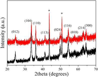 | ||
| Fig. 1 XRD patterns of the bare α-Fe2O3 (black color) and the hybrid α-Fe2O3/Ox-Dex (red color) electrodes. | ||
The morphological evaluation of the bare α-Fe2O3 electrode revealed the presence of macroscopic cracks, indicated with a white arrow (see Fig. 2a). However, such cracks were not observed for the hybrid electrodes (see Fig. 2b), which was attributed to the greater plasticity of the coating due to the presence of the polymeric material and its enhanced mechanical properties due to the favorable hydrogen bonding interactions between the hydroxyl functionalities of the hematite particles and the hydroxyl groups of Ox-Dex. For both electrodes, a tight packing of the cube-like particles was observed in higher magnification FE-SEM images (Fig. 2c and d). Finally, the presence of Ox-Dex was evidenced in the hybrid electrodes to form bridging linkages between the inorganic particles (highlighted with red arrows in Fig. 2f).
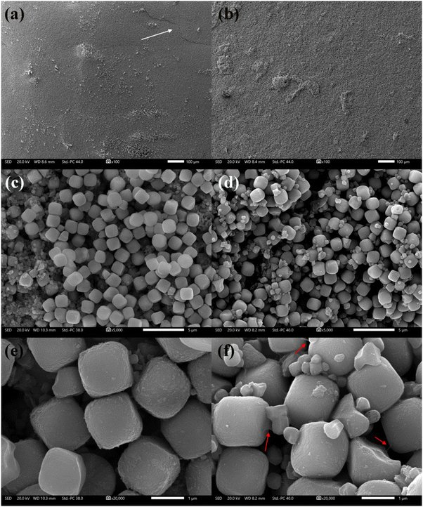 | ||
| Fig. 2 FE-SEM images of the bare α-Fe2O3 (a, c and e) and the hybrid α-Fe2O3/Ox-Dex (b, d and f) electrodes at different magnifications. | ||
The wettability of the α-Fe2O3 and hybrid α-Fe2O3/Ox-Dex electrodes was then studied, and the water contact angle measurement results are shown in Fig. 3. An average water contact angle value of 30 ± 2° was found for the bare α-Fe2O3 electrode, indicating a hydrophilic surface (see Fig. 3a). The hydrophilicity stems from the strong cohesive forces between the water droplet and the hydroxyl groups present on the iron oxide surface.52 Moreover, the hybrid α-Fe2O3/Ox-Dex electrode exhibited a nearly superhydrophilic behavior with a water contact angle of 19 ± 3°, due to the abundance of hydroxyl groups on the inorganic surface and on the polymer chains (see Fig. 3b).53 This highly hydrophilic nature of the hybrid electrodes renders them attractive for use in aqueous electrolyte batteries, ensuring the good wetting of the electrode surface by the aqueous electrolyte solution.
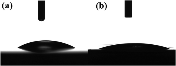 | ||
| Fig. 3 Contact angle measurements on the surface of the bare α-Fe2O3 (a) and the hybrid α-Fe2O3/Ox-Dex (b) electrodes. | ||
3.3 Electrochemical evaluation of the electrodes
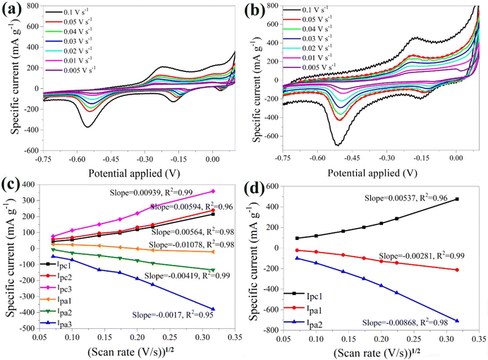
The electrochemical properties of the α-Fe2O3 and the hybrid α-Fe2O3/Ox-Dex electrodes were studied in 1 M Li2SO4 as a conventional Li-based electrolyte. Aqueous ZnSO4 and Al2(SO4)3 electrolyte solutions were also used to investigate the potential use of the electrodes in multivalent ion batteries.Furthermore, the anodic and cathodic maximum currents exhibited a linear dependence on the square root of the scan rate (see Fig. 4b). This suggests that the intercalation/de-intercalation process was controlled by the diffusion of the lithium ions in the host material.63,64 The slopes of the linear dependencies of maximum current and the square root of the potential scan rates were analyzed using the Randles–Sevcik equation:48
| Imax = 2.72 × 10⁵·n3/2·A·CLi·DLi1/2·V1/2 |
Fig. 4c shows the CV plots of the hybrid α-Fe2O3/Ox-Dex anode at different scan rates, ranging from 0.005 V s−1 to 0.1 V s−1. The plots depicted a cathodic peak at −0.17 V and two anodic peaks at −0.15 V and −0.52 V. In particular, the first anodic peak around −0.17 V corresponded to the reduction of α-Li2Fe2O3 to Fe0 and Li2O as discussed above for the α-Fe2O3 bare electrode.66 The pronounced anodic peak at around −0.52 V was again attributed to the irreversible formation of the SEI film.55 Regarding the cathodic peak at −0.17 V, it was associated with the oxidation of Fe0. Interestingly, higher scan rates led to larger specific currents, reaching a maximum value of approximately 800 mA g−1 at a scan rate of 0.1 V s−1. This suggested that the hybrid material exhibited a higher specific current compared to the bare α-Fe2O3 electrode, which was attributed to the hydrogen bonding interactions of the inorganic particles with the oxidized dextran binder, resulting in an increase of the contact points between the active materials.67
Moreover, the anodic and cathodic maximum currents demonstrated a linear dependence on the square root of the potential scan rate (Fig. 4d). The average value of DLi+ for the α-Fe2O3/Ox-Dex anode was found 2.69 × 10⁻¹⁰ cm2 s−1, higher than that of α-Fe2O3 (7.01 × 10⁻¹¹ cm2 s−1). Consequently, a larger amount of Li+ could be intercalated within the α-Fe2O3/Ox-Dex lattice, evidenced also by the higher specific current.
The stability of the bare α-Fe2O3 electrode was explored by varying the number of scans. A noticeable shift in the peaks was detected highlighting the possible instability of the material (Fig. 5a). This behavior was attributed to the loss of material in the electrolyte solution, caused by the electrolysis on the electrode surface and the oxidation of the Cu substrate by Li2SO4.68 During electrolysis, positively charged ions migrate toward the cathode, while negatively charged ions move toward the anode. Prolonged electrolysis results in the accumulation of by-products on the electrode surface, and diminishes the electrochemical performance along with the lifespan of the electrode. The above were also visually evident by the presence of bubbles on the anode surface and the blue coloration of the electrolyte solution due to the oxidation of the Cu substrate (Fig. S3†).
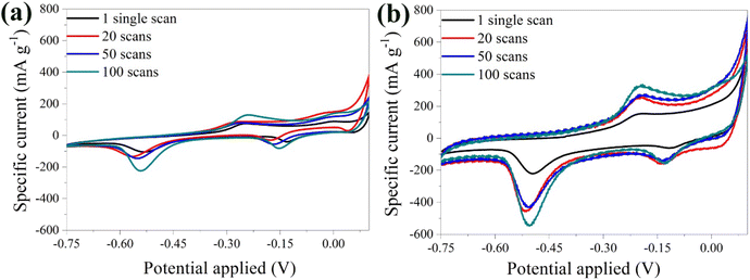 | ||
| Fig. 5 CV curves of the bare α-Fe2O3 (a) and the hybrid α-Fe2O3/Ox-Dex (b) electrodes in 1 M Li2SO4 solution recorded at 1, 20, 50, 100 scans. | ||
Examination of the CV curves of the hybrid electrode at different scan rates (Fig. 5b) showed that the peaks of the first scan exhibited a lower specific current due to the required activation of the material. Subsequent scans, between 20 and 50, coincided, indicating an improved stability of the hybrid anode compared to the bare α-Fe2O3 electrode. This was further confirmed by calculating a variance percentage of 25.5% for the hybrid anode compared to 63% for the bare α-Fe2O3 electrode, derived by calculating the difference between the specific current recorded for the 100th scan and that of the 1st scan divided by the specific current of the 1st scan. The hybrid electrode's improved stability was due to the binder cross-linking ensuring superior structural integrity.41 Most importantly, no material loss was observed in the electrolyte, verifying the excellent recyclability of the material.
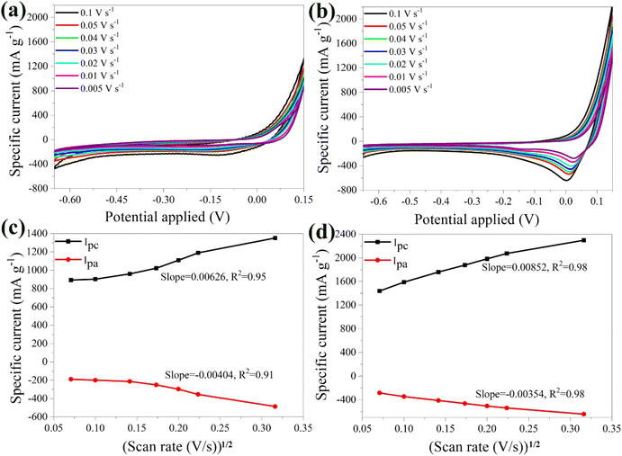
Furthermore, the linear relationship between the maximum current and the square root of the scan rate confirmed that the reaction kinetics were diffusion-controlled (Fig. 6b). From the slope of the curve, the DZn2+ for the α-Fe2O3 electrode was calculated and was found 3.62 × 10⁻¹⁰ cm2 s−1, surpassing the value of Li+. This finding aligns with previous reports, which estimate the diffusion coefficients of Zn2+ between 10−11 − 10−10 cm2 s−1.71 The smaller size of the zinc ions together with their larger charge, enhance their mobility within the active material's lattice compared to the lithium ions.72
Fig. 6c presents the CV plots of the hybrid α-Fe2O3/Ox-Dex electrode at different scan rates (0.005 V s−1 to 0.1 V s−1) in a 1 M ZnSO4 aqueous solution. The hybrid material exhibited a broad peak with maximum current in the anodic area, while a distinct peak was also observed in the cathodic region. This behavior suggests that the redox process may be irreversible. Notably, the maximum current increased as the scan rate approached 0.1 V s−1, indicating a higher Zn2+ storage capacity.73 Interestingly, these curves differ from those of the bare α-Fe2O3 electrode, since the peaks became more prominent at higher scan rates, suggesting that the presence of the polymer enhanced Zn ion diffusion. Furthermore, the anodic and cathodic maximum currents showed a linear relationship with the square root of the scan rate (Fig. 6d). The average DZn2+ for the α-Fe2O3/Ox-Dex anode was 6.46 × 10⁻⁹ cm2 s−1, which is higher than that of the bare α-Fe2O3 electrode in the same electrolyte, in good agreement with the results discussed above for the Li2SO4 electrolyte. Most importantly, this value sets the record for the highest reported diffusion coefficient in aqueous electrolyte in the literature up to date,74–78 apart from one reported very recently for Mo6S8.79
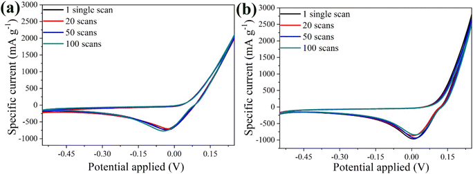
Fig. 7a shows the CV curves of the α-Fe2O3 electrode at a scan rate of 20 mV s−1 for the 1st, 20th, 50th, and 100th scans. An intense peak was observed in the first scan, followed by a gradual decrease in peak intensity in the subsequent scans, suggesting some material aging. Notably, for the 50th and 100th scans, the curves nearly overlapped, indicating that the electrode remained stable and the variance percentage of bare electrode was estimated at 38.1%. In contrast, the CV curves for the hybrid material showed excellent electrochemical stability from the 1st to the 100th scan, with nearly complete overlap and a variance of just 1.3% between the 1st and the 100th scan (Fig. 7b). The peak position remained constant even for higher scan numbers, indicating a reversible phase transition during the Zn2+ intercalation/de-intercalation process.
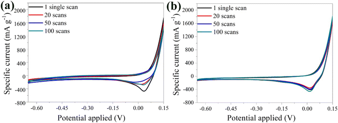 | ||
| Fig. 7 CV curves of the bare α-Fe2O3 (a) and the hybrid α-Fe2O3/Ox-Dex (b) electrodes in 1 M ZnSO4 electrolyte, recorded at 1, 20, 50, 100 scans. | ||
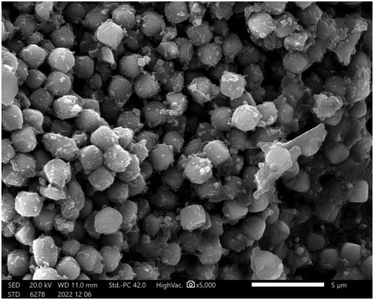
Following 100 continuous intercalation/de-intercalation scans in the 1 M ZnSO4 electrolyte, the hybrid α-Fe2O3/Ox-Dex electrode was characterized by FE-SEM and EDS. Small salt grains from the aqueous ZnSO4 electrolyte were observed on the surface of the pseudocube-shaped particles, however, the hybrid electrodes maintained their integrity and structure (Fig. 8) due to the reasons discussed above. In addition, EDS analysis showed the presence of sulfur after 100 scans, attributed to the ZnSO4 electrolyte on the hybrid electrode surface (Fig. S4†).
| Fe2O3 + 2Al → Al2O3 + 2Fe + 3e− |
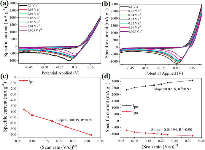
The anodic peak was shifted to lower potentials due to electrochemical polarization, with the effect being more pronounced for scan rates between 0.02 V s−1 and 0.05 V s−1. Moreover, at 0.1 V s−1 strong noise was observed, likely caused by bubble formation on the anode. Despite the above, the bare α-Fe2O3 electrode exhibited a remarkable maximum specific current of 2000 mA g−1 at 0.1 V s−1, the highest among all tested electrolytes (i.e. Li2SO4 (300 mA g−1) and ZnSO4 (1200 mA g−1)). This superior performance was attributed to the trivalent nature of the aluminum ions, resulting in stronger interactions with the anode. The smaller ionic size of the Al3+ cations (r = 68 pm) compared to Zn2+ (74 pm) and Li+ (76 pm),81 further enhanced ion mobility, leading to higher ionic conductivity.10 Furthermore, the maximum current linear relationship with the square root of the scan rate revealed that the reaction kinetics were diffusion-controlled (Fig. 9b). The diffusion coefficient of the Al3+ cations for the bare α-Fe2O3 anode was calculated at 1.91 × 10⁻¹⁰ cm2 s−1, in good agreement with the values reported in the literature, which span from 10−11 cm2 s−1 to 10−8 cm2 s−1 under different conditions.82–85
Fig. 9c presents the CV plots for the hybrid α-Fe2O3/Ox-Dex electrode at scan rates ranging from 0.005 V s−1 to 0.1 V s−1. Unlike the bare α-Fe2O3 anode, the hybrid material exhibited a maximum in the cathodic area at +0.25 V and an anodic peak at 0.00 V. The peak intensities increased with the scan rate, indicating an enhanced Al3+ storage capacity. The maximum specific current was found 3000 mA g−1 at 0.1 V s−1, surpassing that of the bare α-Fe2O3 electrode and all the other electrolytes studied in this work. In addition, the linear relationship between the anodic and cathodic maximum currents and the square root of the scan rate (Fig. 9d) allowed the calculation of DAl3+ for the α-Fe2O3/Ox-Dex anode, which was found 4.64 × 10⁻⁹ cm2 s−1. The higher diffusion coefficient suggests that trivalent aluminum ions entered more rapidly into the material's lattice. Once in the α-Fe2O3/Ox-Dex lattice, the Al3+ ions occupied three sites, thus increasing the number of available electrons and boosting the specific current. Additionally, the presence of cross-linked dextran improved electrode integrity, preventing material loss.
Fig. 10a shows the CV curves of the bare α-Fe2O3 electrode at 20 mV s−1 for the 1st, 20th, 50th and 100th scans. Remarkably, the overlapping curves from the 1st to the 100th scan highlight the excellent electrochemical stability of the anode. The constant peak position and curve shape indicated stable and reversible Al3+ intercalation/de-intercalation processes, supported by visual evidence of insignificant active material loss in the electrolyte during cycling. On the other hand, the performance of the hybrid electrode was superior to that of the bare α-Fe2O3 electrode after the 20th scan, despite a slight decrease in peak intensity after the 1st scan, attributed to minimal material aging (Fig. 10b). Specifically, the variance percentage was calculated 11.6% for α-Fe2O3 and 6.9% for α-Fe2O3/Ox-Dex, signifying an enhanced stability for the hybrid electrode.
4. Conclusions
In this study, sustainable and high-performance hybrid anode electrodes were designed, for applications in multivalent ion batteries. In-house synthesized hematite particles were chosen as the active anode material, while chemically modified dextran, a natural polysaccharide, was utilized as a cross-linkable binder, to immobilize the inorganic particles and enhance the stability of the hybrid electrodes. The design criteria of the proposed electrodes were based on the abundance, environmental friendliness, high chemical functionality, lack of toxicity, hydrophilicity and low cost of the chosen components. The bare and hybrid electrodes were evaluated in terms of their electrochemical performance in various aqueous electrolytes (including Li+, Zn2+, Al3+ ions), while particular emphasis was given to the ion diffusion mechanism and the stability of the material during multiple scans. The α-Fe2O3/Ox-Dex hybrid electrodes, tested in 1 M aqueous ZnSO4, exhibited excellent electrochemical performance with a specific current of 2000 mA g−1 and good stability from the first scan, outperforming the bare α-Fe2O3 electrode (1200 mA g−1). Similar electrochemical results were obtained for the hybrid electrode in 1 M aqueous Al2(SO4)3 solution, which demonstrated a specific current of 3000 mA g−1 and stability up to the 20th scan compared to the bare α-Fe2O3 electrode (2000 mA g−1). Finally, the calculated average diffusion coefficient value, DZn2+, for the α-Fe2O3/Ox-Dex electrode was found exceptionally high at 6.46 × 10⁻⁹ cm2 s−1, one of the highest reported up to date. This remarkable diffusion rate was attributed to the divalent nature of the zinc ions, ensuring faster diffusion of the zinc cations compared to ions with smaller ionic radii. This accelerated diffusion allowed the zinc cations to enter the lattice of the active material more effectively, ensuring stability and minimizing fragmentation of the anode electrode. The pronounced electrochemical performance and stability observed for the α-Fe2O3/Ox-Dex hybrid anodes compared to the α-Fe2O3 analogues were assigned to hydrogen bonding interactions between the functional groups of the two materials. Moreover, these favorable chemical interactions enhanced the specific current and the resistance to volume expansion during the intercalation/de-intercalation processes. Future work will delve into optimizing the fabrication process, exploring additional environmentally friendly components and current collectors such as Ni and stainless steel, and conducting comprehensive assessments under diverse operating conditions for longer scans aiming to advance the understanding of the role of hybrid materials in energy storage systems and to enhance their practical viability in real applications.Data availability
The data supporting the findings of this study can be found in this article or in the ESI.†Conflicts of interest
The authors declare that there are no conflicts of interest.Acknowledgements
This research was funded by the European Union through the Twinning project FORGREENSOFT (Number: 101078989 under HORIZON-WIDERA-2021-ACCESS-03).References
- A. Tomaszewska, Z. Chu, X. Feng, S. O'Kane, X. Liu, J. Chen, C. Ji, E. Endler, R. Li, L. Liu, Y. Li, S. Zheng, S. Vetterlein, M. Gao, J. Du, M. Parkes, M. Ouyang, M. Marinescu, G. Offer and B. Wu, eTransportation, 2019, 1, 100011 CrossRef.
- Y. Chen, Y. Kang, Y. Zhao, L. Wang, J. Liu, Y. Li, Z. Liang, X. He, X. Li, N. Tavajohi and B. Li, J. Energy Chem., 2021, 59, 83–99 CrossRef CAS.
- M. A. Schroeder, L. Ma, G. Pastel and K. Xu, Curr. Opin. Electrochem., 2021, 29, 100819 CrossRef CAS.
- Y. Liu, L. Kang, X. Lu, P. R. Shearing, W. Ahmed, G. He and D. J. L. Brett, in Micro and Nano Technologies, ed. R. K. Gupta, T. A. Nguyen and S. Yasin, Elsevier, 2022, pp. 315–340 Search PubMed.
- X. Li, Y. Tang, H. Lv, W. Wang, F. Mo, G. Liang, C. Zhi and H. Li, Nanoscale, 2019, 11, 17992–18008 RSC.
- C. Xu, B. Li, H. Du and F. Kang, Angew. Chem., Int. Ed., 2012, 51, 933–935 CrossRef CAS.
- J. Ming, J. Guo, C. Xia, W. Wang and H. N. Alshareef, Mater. Sci. Eng., R, 2019, 135, 58–84 CrossRef.
- S. Kang, K. G. Reeves, T. Koketsu, J. Ma, O. J. Borkiewicz, P. Strasser, A. Ponrouch and D. Dambournet, ACS Appl. Energy Mater., 2020, 3, 9143–9150 CrossRef CAS.
- G. A. Elia, K. V. Kravchyk, M. V. Kovalenko, J. Chacón, A. Holland and R. G. A. Wills, J. Power Sources, 2021, 481, 228870 CrossRef CAS.
- T. Leisegang, F. Meutzner, M. Zschornak, W. Münchgesang, R. Schmid, T. Nestler, R. A. Eremin, A. A. Kabanov, V. A. Blatov and D. C. Meyer, Front. Chem., 2019, 7, 1–21 CrossRef.
- H. Wang, S. Chen, C. Fu, Y. Ding, G. Liu, Y. Cao and Z. Chen, ACS Mater. Lett., 2021, 3, 956–977 CrossRef CAS.
- S. Liu, J. J. Hu, N. F. Yan, G. L. Pan, G. R. Li and X. P. Gao, Energy Environ. Sci., 2012, 5, 9743–9746 RSC.
- Y. Liang, H. Dong, D. Aurbach and Y. Yao, Nat. Energy, 2020, 5, 646–656 CrossRef CAS.
- Y. Zhang, X. Zheng, N. Wang, W.-H. Lai, Y. Liu, S.-L. Chou, H.-K. Liu, S.-X. Dou and Y.-X. Wang, Chem. Sci., 2022, 13, 14246–14263 RSC.
- J. Meng, X. Yao, X. Hong, L. Zhu, Z. Xiao, Y. Jia, F. Liu, H. Song, Y. Zhao and Q. Pang, Nat. Commun., 2023, 14, 3909 CrossRef CAS PubMed.
- S. Goriparti, E. Miele, F. De Angelis, E. Di Fabrizio, R. Proietti Zaccaria and C. Capiglia, J. Power Sources, 2014, 257, 421–443 CrossRef CAS.
- P. Roy and S. K. Srivastava, J. Mater. Chem. A, 2015, 3, 2454–2484 RSC.
- J. Chen and F. Cheng, Acc. Chem. Res., 2009, 42, 713–723 CrossRef CAS PubMed.
- P. Kumar, K.-H. Kim, V. Bansal and P. Kumar, Coord. Chem. Rev., 2017, 353, 113–141 CrossRef CAS.
- L. S. Roselin, R. S. Juang, C. T. Hsieh, S. Sagadevan, A. Umar, R. Selvin and H. H. Hegazy, Materials, 2019, 12, 1229 CrossRef CAS PubMed.
- H. Mou, W. Xiao, C. Miao, R. Li and L. Yu, Front. Chem., 2020, 8, 1–14 CrossRef.
- R. Amine, A. Daali, X. Zhou, X. Liu, Y. Liu, Y. Ren, X. Zhang, L. Zhu, S. Al-Hallaj, Z. Chen, G. L. Xu and K. Amine, Nano Energy, 2020, 74, 104849 CrossRef CAS.
- H. Shi, C. Shi, Z. Jia, L. Zhang, H. Wang and J. Chen, RSC Adv., 2022, 12, 33641–33652 RSC.
- S. Fang, D. Bresser and S. Passerini, Adv. Energy Mater., 2020, 10, 1902485 CrossRef CAS.
- S. Lou, Y. Zhao, J. Wang, G. Yin, C. Du and X. Sun, Small, 2019, 15, 1–44 CrossRef.
- X. Zheng and J. Li, Ionics, 2014, 20, 1651–1663 CrossRef CAS.
- L. Zhang, H. Bin Wu and X. W. Lou, Adv. Energy Mater., 2014, 4, 1–11 Search PubMed.
- Y. M. Lin, P. R. Abel, A. Heller and C. B. Mullins, J. Phys. Chem. Lett., 2011, 2, 2885–2891 CrossRef CAS.
- D. Guy, B. Lestriez, R. Bouchet and D. Guyomard, J. Electrochem. Soc., 2006, 153, A679 CrossRef CAS.
- J. Yoon, J. Lee, H. Kim, J. Kim and H.-J. Jin, Polymers, 2024, 16, 254 CrossRef CAS PubMed.
- R. R. Li, Z. Yang, X. X. He, X. H. Liu, H. Zhang, Y. Gao, Y. Qiao, L. Li and S. L. Chou, Chem. Commun., 2021, 57, 12406–12416 RSC.
- S. Lee, H. Koo, H. S. Kang, K.-H. Oh and K. W. Nam, Polymers, 2023, 15, 4477 CrossRef CAS.
- Y. Yang, S. Wu, Y. Zhang, C. Liu, X. Wei, D. Luo and Z. Lin, Chem. Eng. J., 2021, 406, 126807 CrossRef CAS.
- H. Zheng, L. Ma, P. Yi, Z. Fang, Y. Yuan, J. Shen and M. Ye, Nanoscale, 2024, 16, 20765–20773 RSC.
- W. Dou, M. Zheng, W. Zhang, T. Liu, F. Wang, G. Wan, Y. Liu and X. Tao, Adv. Funct. Mater., 2023, 33, 2305161 CrossRef CAS.
- D. Bresser, D. Buchholz, A. Moretti, A. Varzi and S. Passerini, Energy Environ. Sci., 2018, 11, 3096–3127 RSC.
- N. Lingappan, L. Kong and M. Pecht, Renewable Sustainable Energy Rev., 2021, 147, 111227 CrossRef CAS.
- Y. K. Jeong, T. Kwon, I. Lee, T.-S. Kim, A. Coskun and J. W. Choi, Nano Lett., 2014, 14, 864–870 CrossRef CAS.
- M. T. Jeena, J.-I. Lee, S. H. Kim, C. Kim, J.-Y. Kim, S. Park and J.-H. Ryu, ACS Appl. Mater. Interfaces, 2014, 6, 18001–18007 CrossRef CAS.
- M. Ling, J. Qiu, S. Li, C. Yan, M. J. Kiefel, G. Liu and S. Zhang, Nano Lett., 2015, 15, 4440–4447 CrossRef CAS PubMed.
- X. Zhao, C. H. Yim, N. Du and Y. Abu-Lebdeh, Ind. Eng. Chem. Res., 2018, 57, 9062–9074 CrossRef CAS.
- Z. Li, S. Gu, K. Liao, H. Wang, L. Yin, Y. Cao, N. Qin, Q. Gan, Y. Li, Z. Wang, S. Yin and Z. Lu, Mater. Today Energy, 2023, 34, 101298 CrossRef CAS.
- H. Ahn, D. Kim, M. Lee and K. W. Nam, Commun. Mater., 2023, 4, 1–19 CrossRef.
- T. Sugimoto, M. M. Khan and A. Muramatsu, Colloids Surf., A, 1993, 70, 167–169 CrossRef CAS.
- A. Jeanes and C. A. Wilham, J. Am. Chem. Soc., 1950, 72, 2655–2657 CrossRef CAS.
- H. Zhao and N. D. Heindel, Pharm. Res., 1991, 8, 400–402 CrossRef CAS PubMed.
- M. Panagopoulou, D. Vernardou, E. Koudoumas, D. Tsoukalas and Y. S. Raptis, Electrochim. Acta, 2019, 321, 134743 CrossRef CAS.
- S. Daskalakis, M. Wang, C. J. Carmalt and D. Vernardou, Nanomaterials, 2021, 11, 1–8 CrossRef.
- J. M. Meijer and L. Rossi, Soft Matter, 2021, 17, 2354–2368 RSC.
- M. Niederberger, F. Krumeich, K. Hegetschweiler and R. Nesper, Chem. Mater., 2002, 14, 78–82 CrossRef CAS.
- M. Eslami, F. Golestani-fard, H. Saghafian and A. Robin, Mater. Des., 2014, 58, 557–569 CrossRef CAS.
- K. Tang, X. Lv, S. Wu, S. Xuan, X. Huang and C. Bai, ISIJ Int., 2018, 58, 379–400 CrossRef CAS.
- S. Martwiset, A. E. Koh and W. Chen, Langmuir, 2006, 22, 8192–8196 CrossRef CAS PubMed.
- J. Luo, X. Xia, Y. Luo, C. Guan, J. Liu, X. Qi, C. F. Ng, T. Yu, H. Zhang and H. J. Fan, Adv. Energy Mater., 2013, 3, 737–743 CrossRef CAS.
- Y. Xiang, Z. Yang, S. Wang, M. S. A. Hossain, J. Yu, N. A. Kumar and Y. Yamauchi, Nanoscale, 2018, 10, 18010–18018 RSC.
- A. Jaikumar, K. S. V. Santhanam, S. G. Kandlikar, I. B. P. Raya and P. Raghupathi, ECS Trans., 2015, 66, 55 CrossRef CAS.
- J. Zhou, S. Xu, L. Ni, N. Chen, X. Li, C. Lu, X. Wang, L. Peng, X. Guo, W. Ding and W. Hou, J. Power Sources, 2019, 438, 227047 CrossRef CAS.
- C. Costentin and J. M. Savéant, Chem. Sci., 2019, 10, 5656–5666 RSC.
- Y. Guo, X. Li, H. Guo, Q. Qin, Z. Wang, J. Wang and G. Yan, Energy Storage Mater., 2022, 51, 476–485 CrossRef.
- P. Rangaswamy, G. S. Suresh and M. M. Kittappa, J. Solid State Electrochem., 2016, 20, 2619–2631 CrossRef CAS.
- G. J. Wang, Q. T. Qu, B. Wang, Y. Shi, S. Tian, Y. P. Wu and R. Holze, Electrochim. Acta, 2009, 54, 1199–1203 CrossRef CAS.
- S. Siracusano, V. Baglio, N. Van Dijk, L. Merlo and A. S. Aricò, Appl. Energy, 2017, 192, 477–489 CrossRef CAS.
- L. Xu, Y. Tian, T. Liu, H. Li, J. Qiu, S. Li, H. Li, S. Yuan and S. Zhang, Green Energy Environ., 2018, 3, 156–162 CrossRef.
- C. Floraki, M. Androulidaki, E. Spanakis and D. Vernardou, Nanomaterials, 2023, 13, 1850 CrossRef CAS.
- J. M. Lee, G. Singh, W. Cha, S. Kim, J. Yi, S. J. Hwang and A. Vinu, ACS Energy Lett., 2020, 5, 1939–1966 CrossRef CAS.
- X. Liu, W. Si, J. Zhang, X. Sun, J. Deng, S. Baunack, S. Oswald, L. Liu, C. Yan and O. G. Schmidt, Sci. Rep., 2014, 4, 1–8 Search PubMed.
- T. Qin, H. Yang, Q. Li, X. Yu and H. Li, Ind. Chem. Mater., 2024, 2, 191–225 RSC.
- K. Lota, P. Swoboda, I. Acznik, A. Sierczyńska, R. Mańczak, Ł. Kolanowski and G. Lota, Curr. Appl. Phys., 2020, 20, 106–113 CrossRef.
- Z. Li and A. W. Robertson, Battery Energy, 2023, 2, 20220029 CrossRef CAS.
- Y. Shang and D. Kundu, Batteries Supercaps, 2022, 5, e202100394 CrossRef CAS.
- N. Zhang, Y. Dong, M. Jia, X. Bian, Y. Wang, M. Qiu, J. Xu, Y. Liu, L. Jiao and F. Cheng, ACS Energy Lett., 2018, 3, 1366–1372 CrossRef CAS.
- Y. Tan, F. An, Y. Liu, S. Li, P. He, N. Zhang, P. Li and X. Qu, J. Power Sources, 2021, 492, 229655 CrossRef CAS.
- C. Xie, Y. Li, Q. Wang, D. Sun, Y. Tang and H. Wang, Carbon Energy, 2020, 2, 540–560 CrossRef CAS.
- L. Wang, J. Zou, S. Chen, G. Zhou, J. Bai, P. Gao, Y. Wang, X. Yu, J. Li, Y.-S. Hu and H. Li, Energy Storage Mater., 2018, 12, 216–222 CrossRef.
- L. Wen, Y. Wu, S. Wang, J. Shi, Q. Zhang, B. Zhao, Q. Wang, C. Zhu, Z. Liu, Y. Zheng, J. Su and Y. Gao, Nano Energy, 2022, 93, 106896 CrossRef CAS.
- B. Lee, H. R. Lee, H. Kim, K. Y. Chung, B. W. Cho and S. H. Oh, Chem. Commun., 2015, 51, 9265–9268 RSC.
- N. Zhang, M. Jia, Y. Dong, Y. Wang, J. Xu, Y. Liu, L. Jiao and F. Cheng, Adv. Funct. Mater., 2019, 29, 1807331 CrossRef.
- E. Levi, G. Gershinsky, D. Aurbach, O. Isnard and G. Ceder, Chem. Mater., 2009, 21, 1390–1399 CrossRef CAS.
- A. Elgendy, A. A. Papaderakis, A. Ejigu, K. Helmbrecht, B. F. Spencer, A. Groß, A. S. Walton, D. J. Lewis and R. A. W. Dryfe, Nanoscale, 2024, 16, 13597–13612 RSC.
- Y. Wang, X. Song, W. Jiang, G. Deng, X. Guo, H. Liu and F. Li, Trans. Nonferrous Met. Soc. China, 2014, 24, 263–270 CrossRef CAS.
- G. A. Elia, K. Marquardt, K. Hoeppner, S. Fantini, R. Lin, E. Knipping, W. Peters, J. F. Drillet, S. Passerini and R. Hahn, Adv. Mater., 2016, 28, 7564–7579 CrossRef CAS PubMed.
- K. L. Ng, B. Amrithraj and G. Azimi, Joule, 2022, 6, 134–170 CrossRef CAS.
- M. Kazazi, P. Abdollahi and M. Mirzaei-Moghadam, Solid State Ionics, 2017, 300, 32–37 CrossRef CAS.
- J. Tu, M. Wang, X. Xiao, H. Lei and S. Jiao, ACS Sustainable Chem. Eng., 2019, 7, 6004–6012 CrossRef CAS.
- W. Tang, J. Xuan, H. Wang, S. Zhao and H. Liu, J. Power Sources, 2018, 384, 249–255 CrossRef CAS.
Footnotes |
| † Electronic supplementary information (ESI) available. See DOI: https://doi.org/10.1039/d4nr04897k |
| ‡ These authors contributed equally. |
| § Current affiliation: Max-Planck Institute of Colloids and Interfaces, Department of Colloid Chemistry, Am Mühlenberg 1, 14476 Potsdam, Germany. |
| This journal is © The Royal Society of Chemistry 2025 |

