
 Open Access Article
 This Open Access Article is licensed under a Creative Commons Attribution-Non Commercial 3.0 Unported Licence
A novel polymer composite from polyhexamethylene guanidine hydrochloride for high performance triboelectric nanogenerators (TENGs)†
Doan T. Tung a,
Le T. T. Tamab,
Nguyen T. T. Duongab,
Hoang T. Dungab,
Ngo T. Dunga,
Nguyen A. Ducc,
Phan N. Hongd,
Nguyen T. Dunga,
Phan N. Minh*b and
Le T. Lu*ab
a,
Le T. T. Tamab,
Nguyen T. T. Duongab,
Hoang T. Dungab,
Ngo T. Dunga,
Nguyen A. Ducc,
Phan N. Hongd,
Nguyen T. Dunga,
Phan N. Minh*b and
Le T. Lu*ab
aInstitute for Tropical Technology, Vietnam Academy of Science and Technology, 18 Hoang Quoc Viet, Hanoi, Vietnam. E-mail: ltlu@itt.vast.vn
bGraduate University of Science and Technology, Vietnam Academy of Science and Technology, 18 Hoang Quoc Viet, Hanoi, Vietnam. E-mail: pnminh@vast.vn
cDepartment of Physics, Faculty of Basic-Fundamental Sciences, Viet Nam Maritime University, 484 Lach Tray Road, Le Chan, Hai Phong, Vietnam
dCenter for High Technology Research and Development, Vietnam Academy of Science and Technology, 18 Hoang Quoc Viet, Hanoi, Vietnam
First published on 10th January 2025
Abstract
In this study, we report the successful fabrication of a novel antibacterial triboelectric nanogenerator (TENG) using a polymer composite film based on polyhexamethylene guanidine hydrochloride (PHMG). The composite materials, with optimised ingredient ratios, consist of PHMG, polyvinyl alcohol (PVA) and glutaraldehyde (GA) as a crosslinking agent (PHMG-GA-PVA). Utilising 3D printing, these composite materials were directly deposited on the conductive substrates and used as positive TENG electrodes. The obtained results show that the TENGs based on PHMG-GA-PVA exhibit high output efficiency, achieving peak-to-peak open-circuit voltage (Vp–p) and short-circuit current (ISC) values of 664.5 V and 116.8 μA, respectively, at a low operating frequency of 1 Hz with an actuation force of 10 N. The device retains approximately 98% of its initial output voltage value after 360![[thin space (1/6-em)]](https://www.rsc.org/images/entities/char_2009.gif) 000 contact-release cycles.
000 contact-release cycles.
Introduction
Triboelectric nanogenerators are emerging as innovative devices for harvesting mechanical energy from various environmental sources and converting it into electricity. Over the past decade, the development of TENGs has mainly focused on enhancing the conversion efficiency of the devices through new structural designs and electrode materials.1–4 To improve TENG performance, it is necessary to increase the charge density transferred during physical contact, as both open-circuit voltage and short-circuit current depend on the surface charge density. This density is predominantly influenced by the intrinsic properties of the materials used.5,6The triboelectric effect is a universal phenomenon observed in most materials, including metals, wool, wood, and polymers.7,8 Each material exhibits distinct triboelectric properties, influenced by its electron exchange capability, primarily determined by its chemical structure.9–13 Polymers are the most commonly used materials in TENG electrodes. The functional groups present on these polymers play a crucial role in the contact electrification process.14 Electron-withdrawing groups (e.g., fluorine, chlorine, cyanide, ester, carboxyl and nitro), generally yield negative triboelectric properties.15 In contrast, electron-donating groups (e.g. amidogen, amide, hydroxyl and alkoxy) tend to produce positive triboelectric properties.15 In addition, some of the electric generation mechanisms in TENG when contacting different materials such as tribovoltaic nanogenerators (TVNG) and piezoelectric nanogenerator (PENG) have also been thoroughly explained in the literature.16,17
It has been demonstrated that polymers, such as thermoplastic polyurethane (TPU),18,19 polypyrrole (PPy),20,21 polyethylene oxide (PEO),22,23 polybenzimidazole (PBI)24 or polyvinyl alcohol (PVA)25–27 with high mechanical properties, nitrogen-containing composition, or easy processability are commonly used as positive electrodes of TENGs. For example, Xin Jing et al. created a flexible semitransparent dual-electrode hydrogel-based TENG (DH-TENG) with high output when pairing a TPU tribopositive layer with a polydimethylsiloxane (PDMS) negative electrode. The device, achieving voltage of 311.5 V, current of 32.4 μA and a maximum power density of 2.7 W m−2, can quickly charge capacitors and power small electronic devices.18 PVA, a cost-effective polymer, is also frequently utilised in TENG application. Sannathammegowda et al. designed an economical PVA-TENG for mechanical energy harvesting. The uniform PVA membrane as positive friction electrode combined with a polypropylene (PP) negative friction electrode produced an open-circuit voltage VOC and short-circuit current ISC of 21.62 V and 1.72 μA, respectively. The device also demonstrated mechanical durability and electrical stability over more than 5000 successful cycles. Furthermore, it also effectively charged commercial capacitors, digital clocks, and humidity sensors.28
In the current study, we introduce a novel polymer composite by combining PVA and polyhexamethylene guanidine hydrochloride (PHMG) – a cationic polymer containing amino and guanidine groups. PHMG not only exhibits high compatibility with various polymers but also possesses antimicrobial properties,29–34 expanding its potential applications in medical and industrial fields.35–40 The first use of PHMG for TENGs yielded promising results in triboelectric performance. The prepared device reveals a high peak-to-peak open-circuit voltage and peak-to-peak short-circuit current, with values of 664.5 V and 116.8 μA, respectively, at a low operating frequency of 1 Hz. In addition, the device exhibits a high durability, retaining appropriately 98% of its initial output voltage after 360000 operational cycles. The results of this work could pave the way directions for the development of advanced renewable energy sources that meet the growing demand for clean and sustainable energy globally.
Experimental
Materials
Guanidine hydrochloride (GHC, CH5N3HCl 99%), hexamethylene diamine (HMDA, C6H16N2 99%), glutaraldehyde (GA) solution in H2O (50 wt%) were purchased from Sigma-Aldrich (Singapore), polyvinyl alcohol 217 (PVA) was ordered from Kuraray-Poval (Singapore). All chemicals were used as received without any purification.Copper adhesive tape with a thickness of 0.036 mm was ordered from 3 M company. Transparent Fluorinated ethylene propylene (FEP), with an approximately 0.15 mm thickness was purchased from Anycubic. White polyethylene terephthalate glycol (PETG) 3D printing filament is produced by Kingroon.
Preparing for PHMG-GA-PVA printing ink
PHMG was synthesised from GHC and HMDA monomers according to the following procedure: in a typical process, GHC and HMDA were weighed at molar ratio of 1:1 and added in a three-necked flask. The mixture was heated to 125 °C and maintained at this temperature for 4 h. The temperature was then increased to 160 °C and held for additional 4 h, followed by final rise to 180 °C for one hour before cooling to 60 °C. At this temperature, a certain amount of GA was added into the PHMG solution. The mixture was stirred for 2 h to form PHMG-GA. To prepare PHMG-GA-PVA composite, PVA is dissolved in double distilled water at a concentration of 5% by stirring at appropriately 90 °C. The PHMG-GA and PVA solutions were then mixed at the different mass ratios of PHMG-GA:PVA of 1:1; 4:1 and 8:1.
Fabrication of TENG electrode
The TENG PHMG-GA-PVA electrode was fabricated using 3D printing method. The PHMG-GA-PVA gel was directly printed onto 10 × 10 cm2 copper adhesive tape. The printing parameters, including a speed of 20 mm min−1, line width of 0.6 mm, layer thickness of 0.2 mm and substrate temperature of 80 °C were determined. The described 3D printing technique employs a dual-pass method with orthogonal infill patterns. In the initial pass, the printer deposits material along a predetermined axis, creating a series of parallel lines. The second pass then applies material in a direction perpendicular to the first, resulting in a cross-hatched internal structure. After printing, the electrodes were dried in an oven at a temperature of 120 °C overnight. The fabrication process of PHMG-GA-PVA TENG electrode is presented in Fig. 1.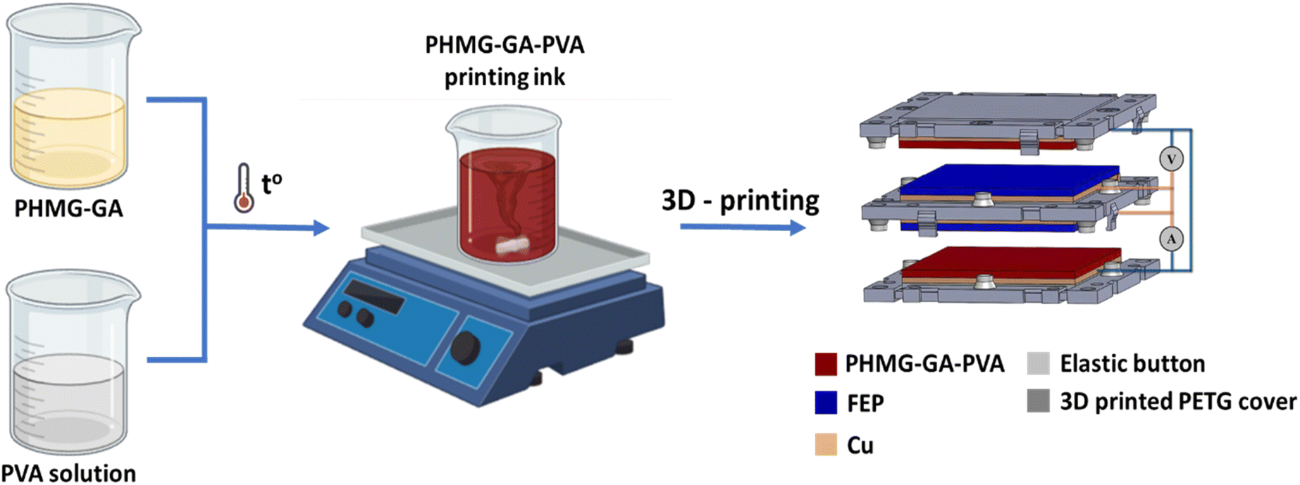 | ||
| Fig. 1 Illustration of the fabrication process for PHMG-GA-PVA TENG electrodes. | ||
Structure of TENG device
The TENG device consists of three 3D-printed parts made from PETG filament. The top and bottom components incorporate PHMG-GA-PVA printed electrodes, which serve as positive friction electrodes, while the middle component has two symmetrical sides mounted on the FEP membrane to act as a negative friction electrode. Rubber buttons, commonly used in computer keyboards, were used to separate the electrodes.Characteristics
FTIR spectra were recorded using a Nicolet 6700 FT-IR spectrometer in the wavenumber range of 4000–400 cm−1. A field emission scanning electron microscope (FE-SEM, HITACHI) equipped with an energy dispersive X-ray spectroscope (EDX) was used to investigate the morphology and elemental composition of the TENG electrode.The open-circuit voltages (OCV or VOC) of the TENG device were characterised using Lecroy Wave Surfer 424 oscilloscope. The short-circuit currents (ISC) of the device were amplified by a low-noise current preamplifier SR570 and measured with a Tektronix DPO4032 oscilloscope.
Mechanical properties were determined by two parameters: impact strength and bending strength. Impact strength was measured using ERICHSEN Impact Tester 304 according to ISO 6272-1 standard. Bending strength was performed using the ELCOMETER 1500 on-axis flexural tester according to ASTM-D522 standard.
The evaluation of the antibacterial efficacy of the PHMG-containing membrane samples coated on copper substrates was conducted using the colony method as follows: initially, the sample (2 cm × 2 cm) was placed on a Petri dish containing 0.4 mL of E. coli (Gram-negative bacteria) or B. subtilis (Gram-positive bacteria) at a density of ∼108 CFU mL−1 and left in contact for 1 hour. The sample was then removed and shaken in 20 mL of 0.9% NaCl solution for 2 minutes. The resulting liquid was diluted 100 times with saline solution. A volume of 100 μL from this dilution was transferred onto Luria-Bertani agar plates, which were then placed in a climate-controlled incubator set at 37 °C for 24 hours. The plates were then carefully examined to identify or count the colonies that had grown on the agar surface. In addition, the PHMG-coated copper membrane was also soaked in double distilled water for 15 minutes before performing the antibacterial test to evaluate the effect of water on the washout of the PHMG membrane.
Results and discussions
Polymer composite material property
Chemical compositions of the materials are characterised using FTIR analysis. Fig. 2 shows FTIR spectra of PVA, PHMG, PHMG-GA and PHMG-GA-PVA prepared at the PHMG-GA:PVA ratio of 8:1. The characteristic peaks of pure PVA (a) used in this study are shown by two strong absorption bands at wavenumbers 1241 cm−1 (C–O–C) and 1087 cm−1 (C–OH), indicating that PVA retains some acetate groups and –OH groups along the polymer chain. The infrared (IR) spectrum of PHMG (b) shows bands at 3158 cm−1 and 1464 cm−1, which are assigned to N–H stretching and bending vibrations of a secondary amine group, respectively. Two absorption peaks at 2932 cm−1 and 2860 cm−1 are characteristic of symmetric and asymmetric stretching vibrations of the CH2 group. The peak at 1621 cm−1 is attributed to the C![[double bond, length as m-dash]](https://www.rsc.org/images/entities/char_e001.gif) N bond. The band at 1353 cm−1 is characteristic of the C–N bond stretching of the secondary amine group. The absorption peaks at 3264 cm−1 and 1160 cm−1 are assigned to O–H stretching and bending vibrations, respectively. The IR spectrum of the PHMG-GA (c) membrane exhibits a characteristic absorption peak of GA at 1100 cm−1, which is assigned to the CO bond stretching vibration.41 The IR spectrum of the PHMG-GA/PVA (d) membrane exhibits a characteristic absorption peak of PVA at 3297 cm−1, which is assigned to the O–H bond stretching vibration of the hydroxyl group. Additionally, two peaks at 1253 cm−1 (C–O–C) and 1024 cm−1 (C–OH) characteristic of PVA, are still present, indicating the presence of PVA in the PHMG-GA-PVA composition.
N bond. The band at 1353 cm−1 is characteristic of the C–N bond stretching of the secondary amine group. The absorption peaks at 3264 cm−1 and 1160 cm−1 are assigned to O–H stretching and bending vibrations, respectively. The IR spectrum of the PHMG-GA (c) membrane exhibits a characteristic absorption peak of GA at 1100 cm−1, which is assigned to the CO bond stretching vibration.41 The IR spectrum of the PHMG-GA/PVA (d) membrane exhibits a characteristic absorption peak of PVA at 3297 cm−1, which is assigned to the O–H bond stretching vibration of the hydroxyl group. Additionally, two peaks at 1253 cm−1 (C–O–C) and 1024 cm−1 (C–OH) characteristic of PVA, are still present, indicating the presence of PVA in the PHMG-GA-PVA composition.
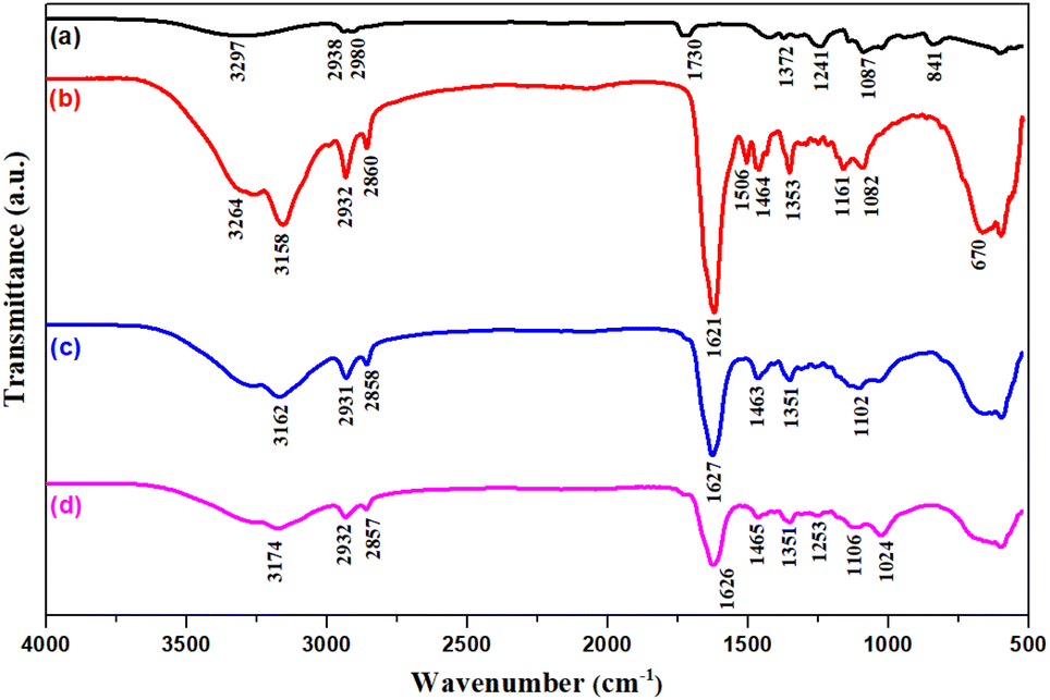 | ||
| Fig. 2 FTIR spectra of PVA (a), PHMG (b), PHMG-GA (c), and PHMG-GA-PVA (at the ratio of 8:1) (d). | ||
Fig. 3 shows the SEM, EDX, and EDX mapping images of the printed polymer electrode composed of PHMG, cross-linking agent GA, and PVA. The SEM image reveals a relatively smooth surface with microstructures and layered printing, reflecting the 3D printing process with sequentially stacked polymer layers. The EDX results identify the presence of elements within the material, with spectral peaks corresponding to the characteristic elements of PHMG (e.g., carbon, chlorine, nitrogen), GA (e.g., oxygen, carbon), and PVA (e.g., carbon, oxygen). Quantitative analysis indicates the relative proportions of these elements, where a higher carbon and oxygen content is expected due to the polymeric nature of the components. The EDX mapping analysis provides a detailed view of the distribution of the elements within the sample. The mapping images show each color representing a different element, highlighting areas where specific elements are concentrated. For instance, a uniform distribution of carbon is expected as all components contain carbon, while oxygen-rich areas correspond to PVA or GA. Furthermore, the presence of nitrogen indicates regions rich in PHMG.
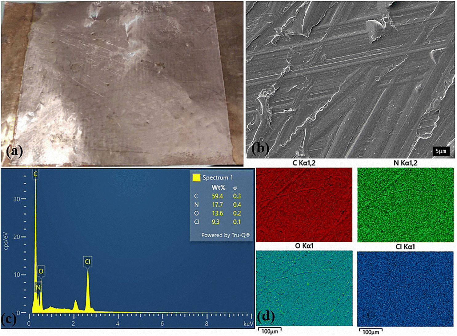 | ||
| Fig. 3 (a) Appearance photo, (b) SEM, (c) EDX and (d) EDX mapping of the 3D-printing PHMG-GA-PVA electrode prepared at PHMG-GA:PVA ratio of 8:1. | ||
Triboelectric properties
To evaluate the triboelectric properties of PHMG, five TENG electrode materials, including pure PVA and PVA with varying PHMG ratios were investigated. Fig. 4 indicates the output open-circuit voltage of the device under the same applied force. It can be seen that the pure PVA electrode generates the lowest voltage, with a positive value of about 181 V and a negative value of around −79 V, indicating the limited electrical generation capacity (Fig. 4a). As the PHMG ratio increases, the electrical performance also improves significantly. For example, at the ratio of PHMG-GA/PVA = 1:1 (PHMG1-GA-PVA1) the sample achieves a maximum positive voltage of approximately 215 V and a negative voltage of around −118 V, while it reaches 387 V (positive) and −137 V (negative) for the ratio of 4:1 (PHMG4-GA-PVA1). These values reach 462 V (positive) and −199 V (negative) at the ratio of 8:1 (PHMG8-GA-PVA1).
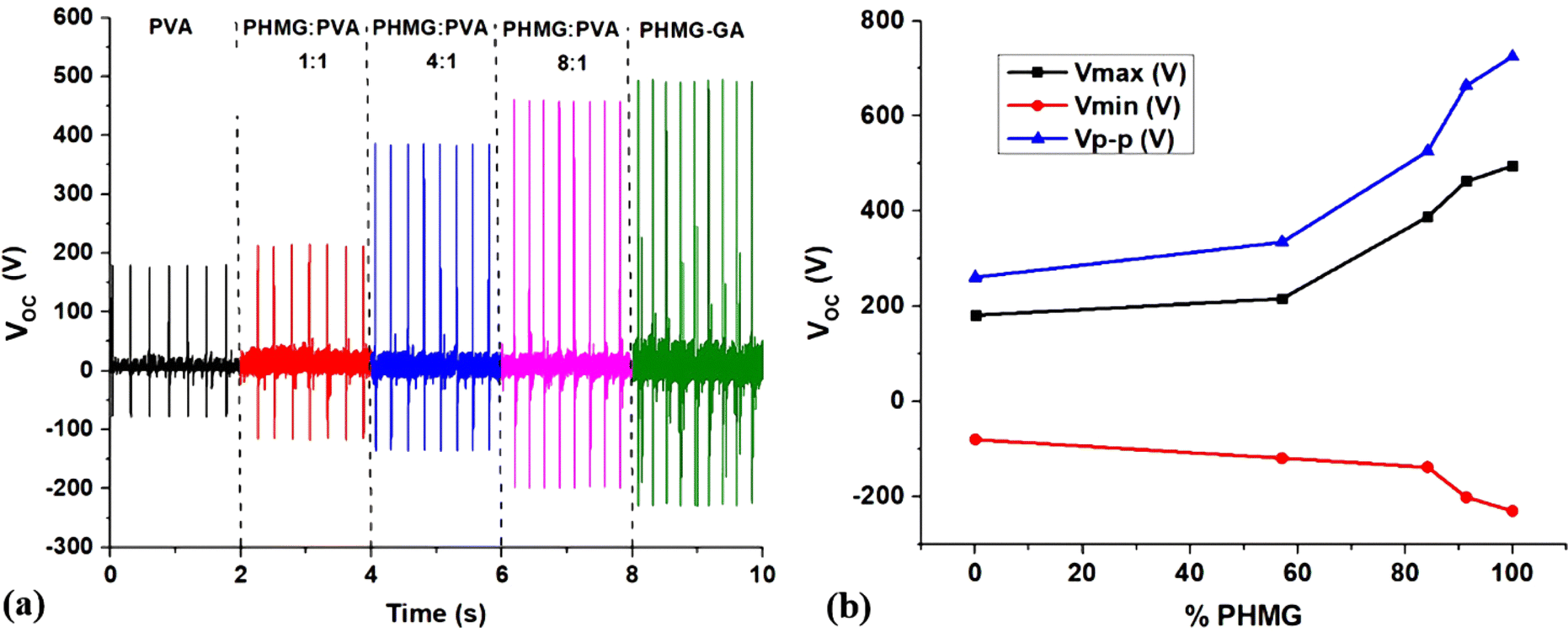 | ||
| Fig. 4 (a) Open circuit voltages (VOC) of PVA, PHMG-GA-PVA and PHMG-GA electrodes prepared at different ratios of PHMG-GA/PVA; (b) maximum (Vmax), minimum (Vmin ), and peak-to-peak (Vp−p) voltages of VOC as a function of PHMG content. | ||
Notably, the PHMG-GA sample without PVA achieves the highest voltages, reaching a maximum positive value of around 494 V and a negative value of approximately −230 V. However, the absence of PVA significantly impacts PHMG's film-forming ability, making it relatively less durable. PHMG tends to form discrete clusters and lacks the ability to form cross-links or stable molecular networks. As a result, during the printing process, the material did not flow evenly and continuously, leading to uneven or interrupted print lines. The resulting film often has cracks, small holes or uneven surfaces and needs a long drying time. In the current study, GA serves as a linker to enhance the structural and mechanical properties of the material.
Fig. 4b and Table 1 show a trend of OCV values changing with the mass percentage of PHMG. It is clear that OCV values increase with the increasing PHMG content. PHMG is a polymer containing guanide reactive groups (NH), which can interact with H+ to form cations (NH+). These active groups carry a positive charge, making PHMG a highly efficient positive tribopolymer. The addition of PVA as a binding agent significantly improves film-forming ability by enhancing intermolecular interactions, thereby improving flexibility and the mechanical strength of the films. Table S1† further compares the maximum generated triboelectric voltage values with other publications showing the role of the new positive friction material PHMG.
| Samples | Vmax (V) | Vmin (V) | Vp–p (V) |
|---|---|---|---|
| PVA | 181 | −79 | 260 |
| PHMG1-GA-PVA1 | 215 | −118 | 333 |
| PHMG4-GA-PVA1 | 387 | −137 | 524 |
| PHMG8-GA-PVA1 | 462 | −199 | 661 |
| PHMG-GA | 494 | −230 | 724 |
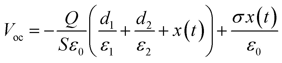
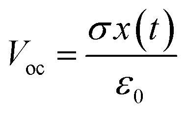
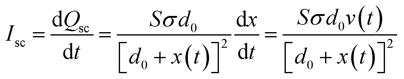
To evaluate the triboelectric properties in more detail, PHMG8-GA-PVA1 sample was selected. Fig. 5 indicates the influence of working frequency on the open circuit voltage (OCV) and short circuit current (ISC). At low operating frequencies (1–5 Hz), the voltage (Vp–p) remains around 664 V, almost unchanged as the operating frequency increase (Table 2). However, the Vp–p value decreases at higher operating frequencies (10 and 20 Hz). According to the basic theory of a contact-separation TENG system, we have the equation:42,43
 | (1) |
 | (2) |
 | (3) |
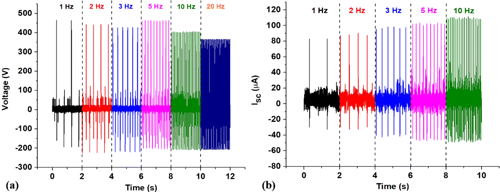 | ||
| Fig. 5 Voc (a) and Isc (b) values at the different working frequencies of PHMG8-GA-PVA1 electrode. | ||
| Frequency (Hz) | Vmax (V) | Vmin (V) | Vp–p (V) | Imax (μA) | Imin (μA) | Ip–p (μA) |
|---|---|---|---|---|---|---|
| 1 | 467.4 | −197.1 | 664.5 | 84.0 | −32.8 | 116.8 |
| 2 | 443.1 | −225.2 | 668.3 | 90.4 | −32.8 | 132.2 |
| 3 | 433.0 | −223.1 | 656.1 | 98.4 | −42.4 | 140.8 |
| 5 | 462.4 | −205.9 | 668.3 | 103.2 | −47.2 | 150.4 |
| 10 | 403.5 | −208.7 | 611.2 | 111.2 | −48.8 | 160.0 |
| 20 | 364.7 | −207.3 | 572.0 | 119.8 | −52.6 | 172.4 |
From eqn (2), it can be seen that the open circuit voltage is independent of the operating frequency. Therefore, in theory, VOC should not change with frequency. This is consistent with the experimental data at low working frequencies (1–5 Hz), as shown in Table 2. However, the experimental data indicate a decrease in VOC at frequencies above 10 Hz. At high frequencies, the reduction in VOC values is possible due to the fact that the impact speed is faster than the recovery time to the initial state of the electrode.44
In addition, according to eqn (3), it can be seen that the short-circuit current ISC is expected to increase with the impact frequency. If the moving speed of the two TENG electrodes is considered constant, the frequency will be proportional to v(t). Thus, a higher frequency corresponds to a larger v(t). This increase in short-circuit current (Isc) with the impact frequency was observed experimentally, as shown in Fig. 5 and Table 2. From Table 2, it is evident that the Isc values of the TENG device utilising the positive electrode material of PHMG8-GA-PVA1 are relatively high compared to some other reports using PVA electrode material.28
As a device that converts mechanical movement into electricity, stability during operation is crucial for practical applications. In this study, a durability test was conducted at an impact frequency of 20 Hz and the results shown in Fig. 6a. The output voltage decreases insignificantly (by only 2%) after 360000 working cycles suggesting that the device can maintain a stable output for an extended period in practical applications. To demonstrate the applicability of the TENG device utilising PHMG-GA-PVA electrode, we connected it with LED systems. As shown in Fig. 6b, all LEDs were lit under full daylight conditions. Additionally, when measuring impact resistance, a 2 kg metal ball dropped from a height of 100 cm showed that the film did not crack or peel off from the copper substrate (Fig. S1a†). In the bending strength test (Fig. S1b†), the film also did not crack or peel off the copper substrate when bent around the smallest diameter axis of the Elcometer 1500 device (2 mm). Therefore, the PHMG8-GA-PVA1 film can be aimed at applications for flexible wearable devices.
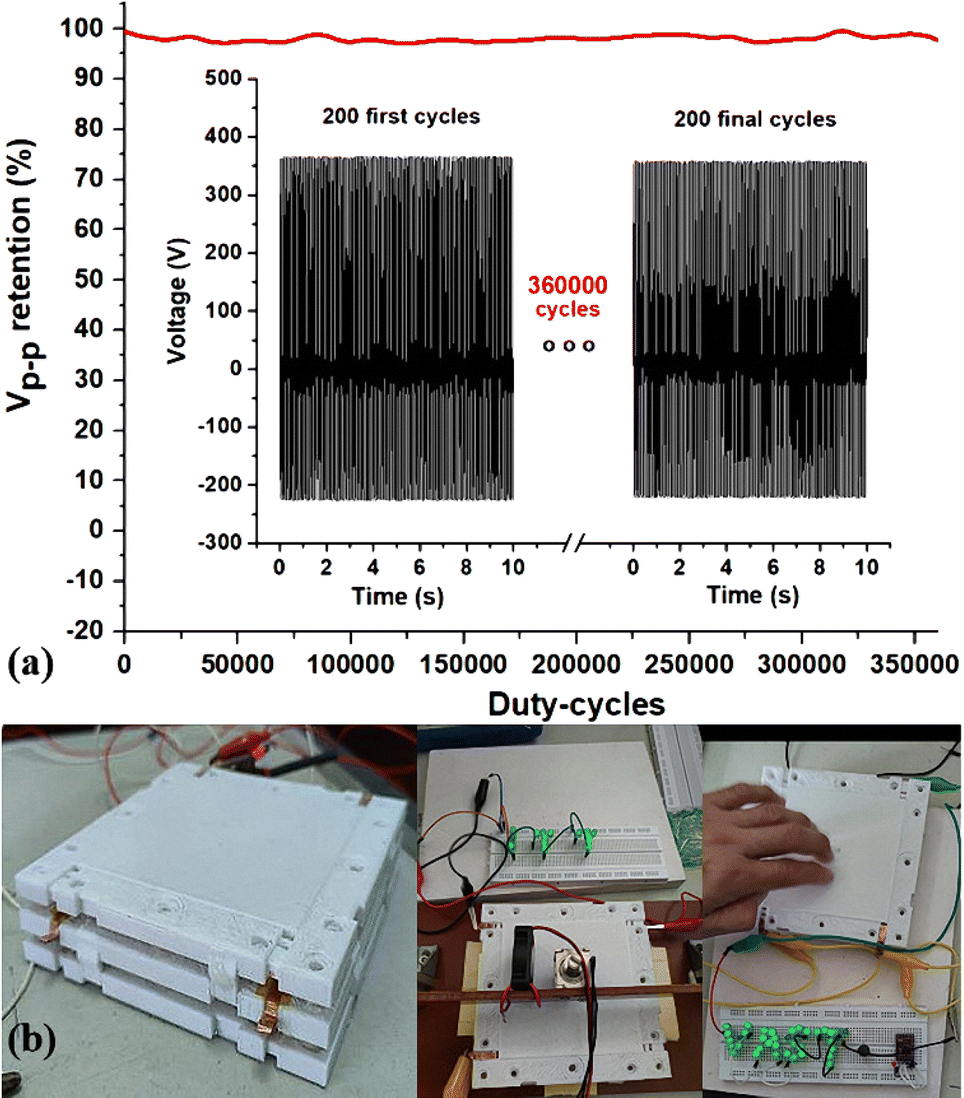 | ||
| Fig. 6 Output voltage decline of a 3D printed PHMG-GA-PVA TENG device after 360000 working cycles (a) and photos of a TENG module used to power for LEDs (b). | ||
Finally, the antibacterial properties of the PHMG8-GA-PVA1 membrane were evaluated, with the results shown in Fig. S2.† PHMG, PHMG-GA, and PHMG8-GA-PVA1 all showed good antibacterial properties, even at a high initial bacterial density of 108 CFU mL−1. After soaking in water for 15 minutes, PHMG without GA was partially hydrolyzed in water and its antibacterial ability was reduced (shown by the appearance of both S. subtilis (gram +) and E. coli (gram −) colonies on the agar surface in the Petri dish). However, when the GA crosslinking agent was present, the membrane exhibited better structural integrity and increased water-resistant. With its strong antibacterial ability, the PHMG8-GA-PVA1 membrane shows great potential for use in antibacterial facemasks and self-deodorized smart shoes.
Conclusions
For the first time, PHMG material-a polymer with strong antibacterial properties, has been successfully utilized in a TENG device as a positive electrode. The results indicate that the PHMG content in the positive electrode affects the output of the TENG device. The presence of amine functional groups of the PHMG combined with GA as cross-linker and PVA enables the device to achieve impressive triboelectric performance, with a peak-to-peak open-circuit voltage of up to 664.5 V and a short-circuit current of 116.8 μA at a low operating frequency of 1 Hz when using a PHMG-GA:PVA ratio of 8:1. At a higher frequency of 20 Hz, the device maintains and output of 572 V and 172 μA under an actuation force of 10 N. Furthermore, the device retains appropriately 98% of its initial output voltage after 360000 operational cycles, suggesting its potential for practical applications such as self-powered devices, sensors, and particularly in antibacterial facemasks and self-deodorized smart shoes.
Data availability
All data supporting the findings of this study are included within the manuscript and as part of the ESI.†Author contributions
Doan T. Tung and Nguyen T. Dung prepared the PHMG-GA-PVA 3D printing solution; Le T. T. Tam synthesised PHMG and performed SEM-EDX analysis; Nguyen T. T. Duong conducted FTIR analysis; Hoang T. Dung designed the printing patterns, electrodes, and TENG device; Ngo T. Dung performed 3D printing and post-processing of TENG electrodes; Nguyen A. Duc and Phan N. Hong carried out triboelectric characterization; Phan N. Minh and Le T. Lu provided scientific guidance and supervision. All authors contributed to writing and revising the manuscript.Conflicts of interest
The authors declare that they have no competing interests.Acknowledgements
This word was funded by Vietnam Academy of Science and Technology under grant number DL0000.08/22-24.References
- J. Si, R. Duan, M. Zhang and X. Liu, Nanomaterials, 2022, 12, 1385 CrossRef CAS PubMed
.
- W. G. Kim, D. W. Kim, I. W. Tcho, J. K. Kim, M. S. Kim and Y. K. Choi, ACS Nano, 2021, 15(1), 258–287 CrossRef CAS PubMed
- Y. Li, Y. Luo, H. Deng, S. Shi, S. Tian, H. Wu, J. Tang, C. Zhang, X. Zhang, J. W. Zha and S. Xiao, Adv. Mater., 2024, 2314380 CrossRef CAS PubMed
- M. M. Rastegardoost, O. A. Tafreshi, Z. Saadatnia, S. Ghaffari-Mosanenzadeh, C. B. Park and H. E. Naguib, Nano Energy, 2023, 111, 108365 CrossRef CAS
- V. A. Cao, S. Lee, M. Kim, M. M. Alam, P. Park and J. Nah, Nano Energy, 2020, 67, 104300 CrossRef CAS
- R. L. Bulathsinghala, A. Ravichandran, H. Zhao, W. Ding and R. Dharmasena, Nano Energy, 2024, 123, 109383 CrossRef CAS
- A. F. Yu, Y. X. Zhu, W. Wang and J. Y. Zhai, Adv. Funct. Mater., 2019, 29, 1900098 CrossRef CAS
- X. Zhang, Y. Zhang, J. Zhang, J. Shang, L. Lin, Q. Liu and Q. An, Chem. Eng. J., 2024, 483, 149314 CrossRef CAS
- S. M. Hsu and R. S. Gates, J. Phys. D: Appl. Phys., 2006, 39, 3128 CrossRef CAS
- Y. Wang, N. Yamada, J. Xu, J. Zhang, Q. Chen, Y. Ootani, Y. Higuchi, N. Ozawa, M.-I. D. B. Bouchet, J. M. Martin, S. Mori, K. Adachi and M. Kubo, Sci. Adv., 2019, 5, eaax9301 CrossRef CAS PubMed
- C. A. Mizzi, A. Y. W. Lin and L. D. Marks, Phys. Rev. Lett., 2019, 123, 116103 CrossRef CAS PubMed
- H. Ko, Y. W. Lim, S. Han, C. K. Jeong and S. B. Cho, ACS Energy Lett., 2021, 6, 2792–2799 CrossRef CAS
- D. Kang, H. Y. Lee, J.-H. Hwang, S. Jeon, D. Kim, S. Kim and S.-W. Kim, Nano Energy, 2022, 100, 107531 CrossRef CAS
- S. Li, J. Nie, Y. Shi, X. Tao, F. Wang, J. Tian, S. Lin, X. Chen and Z. L. Wang, Adv. Mater., 2020, 32, 2001307 CrossRef CAS PubMed
- A. Chen, C. Zhang, G. Zhu and Z. L. Wang, Adv. Sci., 2020, 7, 2000186 CrossRef CAS PubMed
- Z. Liu, S. Lin, P. Yang, S. Qin, J. Hun and X. Chen, Energy Environ. Sci., 2024, 17, 6582–6593 RSC
- S. Qin, J. Chen, P. Yang, Z. Liu, X. Tao, X. Dong, J. Hu, X. Chu, Z. L. Wang and X. Chen, Adv. Energy Mater., 2024, 14, 2303080 CrossRef CAS
- X. Jing, H. Li, H. Y. Mi, P. Y. Feng, X. Tao, Y. Liu, C. Liu and C. Shen, J. Mater. Chem. C, 2020, 8, 5752 RSC
- H. Joo, S. Gwak, M. H. Lee, H. Park, C. Lee, J. H. Lee, S. A Han and J. H. Lee, Sustainable Mater. Technol., 2023, 36, e00638 CrossRef CAS
- H. Zhang, P. Zhang, L. Deng, W. Zhang, B. Liu, D. Ren and Z. Yang, ACS Appl. Nano Mater., 2022, 5(8), 11219–11228 CrossRef CAS
- Q. Tang, Q. Ke, Q. Chen, X. Zhang, J. Su, C. Ning and L. Fang, ACS Appl. Mater. Interfaces, 2023, 15(14), 17641–17652 CrossRef CAS PubMed
- P. Ding, J. Chen, U. Farooq, P. Zhao, N. Soin, L. Yu, H. Jin, X. Wang, S. Dong and J. Luo, Nano Energy, 2018, 46, 63–72 CrossRef CAS
- Z. Qian, R. Li, J. Guo, Z. Wang, X. Li, C. Li, N. Zhao and J. Xu, Nano Energy, 2019, 64, 103900 CrossRef CAS
- X. Tao, P. Yang, Z. Liu, S. Qin, J. Hu, Z.-X. Huang, X. Chen and J.-P. Qu, ACS Nano, 2024, 18(5), 4467–4477 CrossRef CAS PubMed
- S. Wang and Y. Zhang, Mater. Technol., 2022, 37(13), 2752–2757 CrossRef CAS
- I. C. M. Candido, G. S. Oliveira, S. J. L. Ribeiro, M. Cavicchioli, H. S. Barud, L. G. Silva and H. P. de Oliveira, Nano Energy, 2023, 105, 108035 CrossRef CAS
- S. Yempally, J. J. Cabibihan and D. Ponnamma, Energy Technol., 2024, 12, 2300992 CrossRef CAS
- S. Amini, R. F. S. M. Ahmed, S. M. Ankanathappa and K. Sannathammegowda, Nanotechnology, 2023, 35(3), 035403 CrossRef PubMed
- D. T. Nguyen, L. T. Pham, H. T. T. Le, M. X. Vu, H. T. M. Le, H. T. M. Le, N. H. Pham and L. T. Lu, RSC Adv., 2018, 8, 19707–19712 RSC
- J. Chen, D. Wei, W. Gong, A. Zheng and Y. Guan, ACS Appl. Mater. Interfaces, 2018, 10(43), 37535–37543 CrossRef CAS PubMed
- S. Chen, C. Li, T. Hou, Y. Cai, L. Liang, L. Chen and M. Li, React. Funct. Polym., 2019, 145, 104379 CrossRef
- Q. Lin, L. Wu, W. Hu, X. Wan, Z. Wu and C. Zhang, Surf. Interface, 2022, 29, 101708 CrossRef CAS
- B. Qiu, M. Wang, W. Yu, S. Li, W. Zhang, S. Wang and J. Shi, Polymers, 2023, 15, 1521 CrossRef CAS PubMed
- Y. Zhao, D. Wei, X. Xu and Y. Guan, Polym. Advan. Technol., 2024, 35, e6314 CrossRef CAS
- M. Sahraro, H. Yeganeh and M. Sorayya, Mater. Sci. Eng. C, 2016, 59, 1025–1037 CrossRef CAS PubMed
- H. Choi, K. J. Kim and D. G. Lee, Fungal Biol., 2017, 121(1), 53–60 CrossRef CAS PubMed
- C. Zhang, Z. Ying, Q. Luo, H. Du, Y. Wang, K. Zhang, S. Yan, X. Li, Z. Shen and W. Zhu, J. Polym. Sci., Part A: Polym. Chem., 2017, 55, 2027–2035 CrossRef CAS
- Y. Zhu, Y. Gu, S. Qiao, L. Zhou, J. Shi and H. Lai, J. Biomed. Mater. Res., Part A, 2017, 105, 871–878 CrossRef CAS PubMed
- S. Zhang, D. Wei, X. Xu and Y. Guan, Coatings, 2023, 13, 1115 CrossRef CAS
- W. Y. Wang, H. W. Hu, J. C. Chiou, K. F. Yung and C. W. Kan, Polym. Chem., 2023, 14, 5226–5252 RSC
- H. Hu, J. H. Xin, H. Hu, A. Chan and L. He, Carbohydr. Polym., 2013, 91(1), 305–313 CrossRef CAS PubMed
- S. Niu, S. Wang, L. Lin, Y. Liu, Y. S. Zhou, Y. Hu and Z. L. Wang, Energy Environ. Sci., 2013, 6(12), 3576–3583 RSC
- S. Hu, J. Han, Z. Shi, K. Chen, N. Xu, Y. Wang, R. Zheng, Y. Tao, Q. Sun, Z. L. Wang and G. Yang, Nano-Micro Lett., 2022, 14, 115 CrossRef CAS PubMed
- H. T. Deng, Z. Y. Wang, Y. L. Wang, D. L. Wen and X. S. Zhang, Microsyst. Nanoeng., 2022, 8, 61 CrossRef CAS PubMed
Footnote |
| † Electronic supplementary information (ESI) available. See DOI: https://doi.org/10.1039/d4ra07768g |
| This journal is © The Royal Society of Chemistry 2025 |