
 Open Access Article
 This Open Access Article is licensed under a
 Creative Commons Attribution 3.0 Unported Licence
Microstructure, wear, and corrosion properties of PEEK-based composite coating incorporating titania- and copper-doped mesoporous bioactive glass nanoparticles
Khalil Ahmada,
Ayman Imranb,
Badar Minhas b,
Aqsa Aizazb,
Abdul Khaliqc,
Abdul Wadooda,
Muhammad Haseeb Nawazb,
Muhammad Tajammal Chughtaic,
Rahila Batuld and
Muhammad Atiq Ur Rehman*a
b,
Aqsa Aizazb,
Abdul Khaliqc,
Abdul Wadooda,
Muhammad Haseeb Nawazb,
Muhammad Tajammal Chughtaic,
Rahila Batuld and
Muhammad Atiq Ur Rehman*a
aDepartment of Materials Science and Engineering, Institute of Space Technology, Islamabad, Pakistan. E-mail: atique1.1@hotmail.com
bCentre of Excellence in Biomaterials and Tissue Engineering, Materials Science Engineering Department, Government College University, Lahore 54000, Pakistan
cCollege of Engineering, University of Hail, Saudi Arabia
dCollege of Pharmacy, University of Hail, Saudi Arabia
First published on 21st January 2025
Abstract
Poor wear- and corrosion-resistance of 316L SS implants are critical problems in orthopedic implants. This study aims to improve the wear- and corrosion-resistance of 316L SS through surface coating. In this study, a bilayer composite coating consisting of polyether ether ketone (PEEK) as the first layer, and titania (TiO2)- and Cu-doped mesoporous bioactive glass nanoparticles (Cu-MBGNs) were deposited as the second layer on a 316L SS via electrophoretic deposition (EPD). Scanning electron microscopy (SEM) images of the bilayer composite coating showed the distribution of TiO2 and Cu-MBGNs within the PEEK matrix. Energy dispersive spectroscopy (EDS) analysis confirmed the presence of TiO2 and Cu-MBGNs in the bilayer composite coating. Fourier transform infrared spectroscopy (FTIR) identified the functional groups attributed to the PEEK, TiO2 and Cu-MBGNs. X-ray diffraction (XRD) analysis confirmed the presence of TiO2 (anatase) and Cu-MBGNs in the bilayer composite coating. The coating exhibited a strong antibacterial effect against Staphylococcus aureus (S. aureus) and Escherichia coli (E. coli). Incorporating TiO2/Cu-MBGNs into the bilayer composite coating significantly modified the surface of 316L SS by improving the wear- and corrosion-resistance. Pin on disc test revealed that the specific wear rate of ∼(0.4570 ± 0.009) × 10−6 mm3 Nm−1 of the PEEK coating decreased to (0.0482 ± 0.007) × 10−6 mm3 Nm−1 on incorporating TiO2/Cu-MBGNs in PEEK coating under a normal load of 10 N in Dulbecco's Modified Eagle Medium (DMEM). Furthermore, electrochemical impedance spectroscopy (EIS) results revealed that the impedance value of the bilayer composite coating remained ∼4.56 × 10⁵ Ω cm2 compared to 8.81 × 10³ Ω cm2 of 316L SS after 24 h immersion in phosphate-buffered saline (PBS). Thus, this study demonstrated that the wear- and corrosion-resistance of 316L SS can be improved by incorporating TiO2/Cu-MBGNs in PEEK-based composite coatings for orthopedic applications.
1. Introduction
Austenitic low carbon stainless steel (316L SS) is a favourable alloy for load bearing and maintaining structural integrity in orthopedic applications owing to its low cost and ease of fabrication.1–4 However, 316L SS corrodes in the human body, which leads to adverse biological reactions5–7 due to the uncontrolled release of toxic metal ions (Fe2+, Cr6+, and Ni2+, etc.) that cause immunological responses, such as allergies in patients.8 Corrosion of 316L SS implants in physiological fluids is a significant cause for failure of the implants, and it is reported that almost 90% of implants fail due to corrosion attack.9 Furthermore, the poor wear resistance of 316L SS implants causes loosening of the implant,10,11 and wear debris can initiate allergic reactions to surrounding tissues.12The wear and corrosion resistance of 316L SS implants can be improved through surface modification by depositing a biocompatible, bioactive, antibacterial, wear and corrosion-resistance coating on the surface of 316L SS.13–15 Bioactive coatings, including 45S5 bioglass (BG), hydroxyapatite (HA), mesoporous bioactive glass nanoparticles (MBGNs), and ceramic coatings, which include alumina and titania, and polymer coatings, such as PEEK coating, are ideal for modifying the surface of 316L SS. These coatings can be deposited via electrophoretic deposition technique.16,17
EPD is one of the robust techniques for depositing biopolymers, bioceramics, and composite coatings in biomedical implants with simple and intricate shapes at room temperature.18 There are two types of EPD, cathodic and anodic, depending on the net charge of the particles acquired in a stable suspension. In the first step of EPD, the particles are charged positively or negatively to form a stable colloidal suspension. An electric field is applied in the second step; the charged particles migrate toward the oppositely charged,18–20 and the charged particles are deposited to form a uniform coating.21
PEEK is a synthetic thermoplastic that exhibits biocompatibility, wear resistance, chemical resistance, mechanical strength, and radiolucency.22 Nevertheless, PEEK as a coating material offers surface modification of metallic implants by coating because the elastic modulus of PEEK (3–4 GPa) is close to that of cortical bone (7–30 GPa).22,23 The bio-inertness of PEEK can be mitigated by incorporating bioactive agents.24 Cu-MBGNs provide multifunctional activities, such as angiogenesis (release of Cu2+ ions), osteogenesis, and osteopromotive release of Ca and P ions, and an antibacterial effect inhibiting biofilm formation.25–27 Titania (TiO2, anatase phase) is a highly biocompatible, wear- and corrosion-resistant ceramic material recommended for orthopedic applications, such as artificial hip and knee replacements. When TiO2 is used for bone tissue replacement, it enhances the implant's integration with host tissues.
Various researchers have recently studied PEEK-based coatings.28,29 These coatings focus on achieving bioactive and antibacterial properties.30,31 However, the mechanical properties are yet to be investigated in detail. Thus, this is a critical research gap. Poor adhesion between the two layers deposited via EPD can result in the release of wear debris. Resistance improving the coating's adhesion strength, corrosion resistance, and wear resistance is essential.32–34 Rehman et al.35 deposited a PEEK/BG layer on 316L SS to improve wear resistance, corrosion resistance, and bioactivity. The chitosan/Lawson/BG was deposited on the PEEK/BG layer to impart the antibacterial property and to provide the controlled release of Lawson. Nawaz et al.31 developed chitosan/gelatin/Ag–Mn MBGN composite coating on the PEEK/BG layer (deposited on stainless steel via EPD) to upregulate osteoblast cell attachment and proliferation in addition to antibacterial activity. Rehman et al.36 reported that PEEK and PEEK/bioactive glass composite coatings could withstand a 7 N applied load during a tribology test. Kumari et al.37 incorporated an extract of jack fruit latex resin into poly(methyl methacrylate) (PMMA) to modify the antibacterial and bioactive properties of dental-based materials. Kumari et al.38 also developed PMMA-based zirconia reinforced bio nanocomposites to improve the structural, mechanical and biological properties of dental applications. Kumari et al.39 developed PMMA-based nanocomposite materials by incorporating MgO for dental applications.
Previous studies followed a “sintered-then-deposit” sequence for PEEK-based composite coatings, while in this study, we innovatively explored a deposit-then-sintered approach. This newly developed process improved the wear- and corrosion-resistance of 316L SS implants for orthopedic applications. In previous studies on PEEK-based composite coatings, the PEEK layer was first deposited and sintered. Afterward, the second layer of bioactive glass particles was deposited.
The primary purpose of this study is to address the limitations of the adhesion strength of PEEK coating in tribological analysis. In our previous study,40 a PEEK coating was delaminated under a 1 N normal applied load and subjected to a pin-on-disc test in the presence of Dulbecco's Modified Eagle Medium (DMEM), and its adhesion strength was compromised. The present study investigated the synergistic effect on the final coating surface developed by incorporating TiO2/Cu-MBGNs in a PEEK coating deposited on 316L SS electrophoretically and sintered to improve wear- and corrosion-resistance. This study aims to improve the wear- and corrosion-resistance of 316L SS in human physiological fluid. The information obtained from this study can further be helpful for in vivo trials and clinical investigations, leading to commercialization. An improvement in the wear- and corrosion-resistance of the 316L SS substrate will enhance the lifespan of orthopedic implants, reduce the risk of implant failure, and improve patient satisfaction.
The significance of this study demonstrates that incorporating the TiO2/Cu-MBGNs in bilayer composite coating improves the structural morphology by eliminating the micro-voids in the PEEK layer. This improved morphology of the bilayer composite coating ultimately unprecedently improved the wear- and corrosion-resistance of the bilayer composite coating. This bilayer composite coating has significant potential for orthopedic applications.
2. Materials and methods
2.1. Materials
AISI 316 L SS foil of 1 mm thickness was used to prepare the substrates for coatings. The composition of 316L SS was Cr-16.5%, Ni-10%, Mo-2%, N-0.10%, S-0.015%, P-0.045%, C-0.03%, Si-1.00%, Mn-2.00%, and Fe (balance%).41 PEEK 704 was purchased from Victrex, UK. TiO2 powder (CAS-No. XF 180, purity ≥99.5%) was purchased from XFNANO, China. The chemicals (hexadecyltrimethyl ammonium bromide (CTAB, CAS-No. 57-09-0, purity ≥99%), calcium nitrate tetrahydrate (CAS-No. 13477-34-4, purity ≥99.0%), ammonia solution (CAS-No. 1336-21-6, purity = 32%), and ethyl acetate (CAS-No. 141-78-6, purity ≥99.5%)) for the synthesis of Cu-doped MBGNs were purchased from Sigma-Aldrich (Germany). Tetraethyl orthosilicate (TEOS, CAS-No. 78-10-4, purity ≥99.0%) was purchased from Merck Millipore (Germany).2.2. Methods
A sheet cutter was used to cut a 316L SS sheet in the dimension of (3 × 1.5) cm2. The substrates were washed and cleaned with a solution of acetone, followed by washing with ethanol, keeping their ratio as 1![[thin space (1/6-em)]](https://www.rsc.org/images/entities/char_2009.gif) :1 in an ultra-sonication bath for 10 min. Then, the substrates were rinsed in distilled water and dried in air.
:1 in an ultra-sonication bath for 10 min. Then, the substrates were rinsed in distilled water and dried in air.
Copper-doped mesoporous bioactive glass nanoparticles (Cu-MBGNs) with a composition of (70 mol% SiO2, 25 mol% CaO, and 5 mol% CuO)26 were synthesized by applying the modified Stöber method.42 First, 2.24 g of C-TAB (soft template) was dissolved in 104 mL of water, and continuous stirring was performed for 15 min. Then, 32 mL of ethyl acetate was added dropwise to the solution. Afterward, 22 mL of ammonium hydroxide (28%) was used to maintain a pH ∼9–10, and then 23.04 mL of TEOS was added dropwise in the solution via burette. Finally, 5.21 g of calcium nitrate and copper nitrate were added to the solution. Copper nitrate was added according to the desired composition, which is 5 mol% – (0.869 g in 5.21 g). The solution was stirred at 250 rpm for 4 h and then placed at room temperature for 12 h. Then, the suspension was centrifuged at 10000 rpm for 10 min from the parent's solvent and washed four times with ethanol and distilled water equally. These particles were dried at 37 °C for 24 h and then calcined at 700 °C for 3 h at a 10 °C min−1 heating rate in the box furnace (KSL-1700X-A7), and then particles were furnace cooled and used in the development of TiO2/Cu-MBGNs layer.43
In this study, the PEEK coating was deposited as the first layer (base layer) on 316L SS via EPD with an applied electric field of 20 V cm−1 with less deposition time, i.e., 1 min instead of 3 min, to achieve a relatively thin coating.40 A stable suspension containing 20 g L−1 PEEK (∼10 μm average particle size) in 50 mL of chitosan solution (chitosan solution of 0.5 g L−1 was prepared separately) was prepared.44,45 Chitosan solution was used to prepare the suspension owing to its suitability for the deposition of bioceramics, as discussed in previous studies.14,46 The suspension of PEEK was subjected to magnetic stirring for 30 min, followed by ultrasonication for 30 min and magnetic stirring for 10 min. The pH of the PEEK suspension was maintained between 4 and 5 because, in this pH value, the PEEK particles, along with chitosan macromolecules, were positively charged in the suspension. A detailed investigation of the optimization of EPD parameters along with deposition mechanisms was presented in ref. 40. When the stable PEEK suspension was subjected to EPD, the positively charged PEEK particles were deposited on the oppositely charged electrode of 316L SS (cathode) under the influence of a 20 V cm−1 applied electric field with a deposition time of 1 min. The reactions involved in the deposition mechanism of PEEK are illustrated in Subsection 3.1. After deposition of the PEEK coating on 316L SS, the coatings were subjected to sintering at 350 °C/30 min at a heating rate of 10 °C min−1 for complete densification.40
The second layer (the top layer) of TiO2/Cu-MBGNs was deposited on the sintered PEEK layer. A stable suspension of TiO2/Cu-MBGNs was prepared in the ethanol solution, in which 0.1 g of TiO2 (anatase) (0.2% w/v) and 0.2 g of Cu-MBGNs (0.4% w/v) were added to a 50 mL ethanol solution to prepare a stable suspension. A 0.1 g of TiO2 was added to 0.2 g of Cu-MBGN suspension to improve mechanical, tribological, and corrosion resistance properties.47,48 A systematic study was conducted to optimize the required concentration of TiO2 in the Cu-MBGN suspension to obtain the desired properties. First, TiO2 was added at a minimum concentration, i.e., 0.025 g in Cu-MBGN suspension in ethanol, which improved some properties. Moreover, it could not impart the desired mechanical (adhesion strength), tribological, and corrosion resistance levels. Thus, the concentration of TiO2 was increased with an interval of 0.025 g in 0.2 g in a 50 mL suspension of Cu-MBGNs. The desired properties were achieved at a concentration of 0.1 g TiO2 in 0.2 g Cu-MBGNs in a 50 mL suspension. The suspension of TiO2/Cu-MBGNs in ethanol solution was subjected to magnetic stirring for 1 h, followed by probe sonication for 40 min. This process was repeated three times until the particles were homogenized in the suspension. Furthermore, the pH of the suspension was maintained at 3–4 by adding 3 mL of acetic acid dropwise in the suspension. In this pH range, particles of TiO2 and Cu-MBGNs were positively charged in the ethanol suspension. The PEEK coating, after sintering, was immersed in a stable suspension of TiO2/Cu-MBGNs. An electric field of 50 V cm−1 for 3 min was applied to the suspension. The positively charged particles of TiO2 and Cu-MBGNs were forced to move and deposit onto the sintered PEEK layer already deposited on the 316L SS electrode (cathode), producing a uniform coating (second layer) on 316L SS.48,49 The second layer of TiO2/Cu-MBGNs was deposited at a higher applied electric field and deposition time because a higher driving force was required to overcome the nonconductive sintered PEEK layer already deposited on 316L SS. After the deposition of the second layer, the coated samples were dried at room temperature and then again sintered at 350 °C in the box furnace for 30 min at a 10 °C min−1 heating rate, followed by furnace cooling.33,48 The newly developed sintering cycle densified and compacted both layers into a single layer. Moreover, deposition was made into layers, so the developed coating was called a bilayer composite coating. The deposition mechanism of TiO2/Cu-MBGNs on the sintered PEEK layer is illustrated in Subsection 3.1. Fig. 1 shows the sequential steps of deposition and sintering of the PEEK layer and TiO2/Cu-MBGNs layer on 316L SS via EPD.
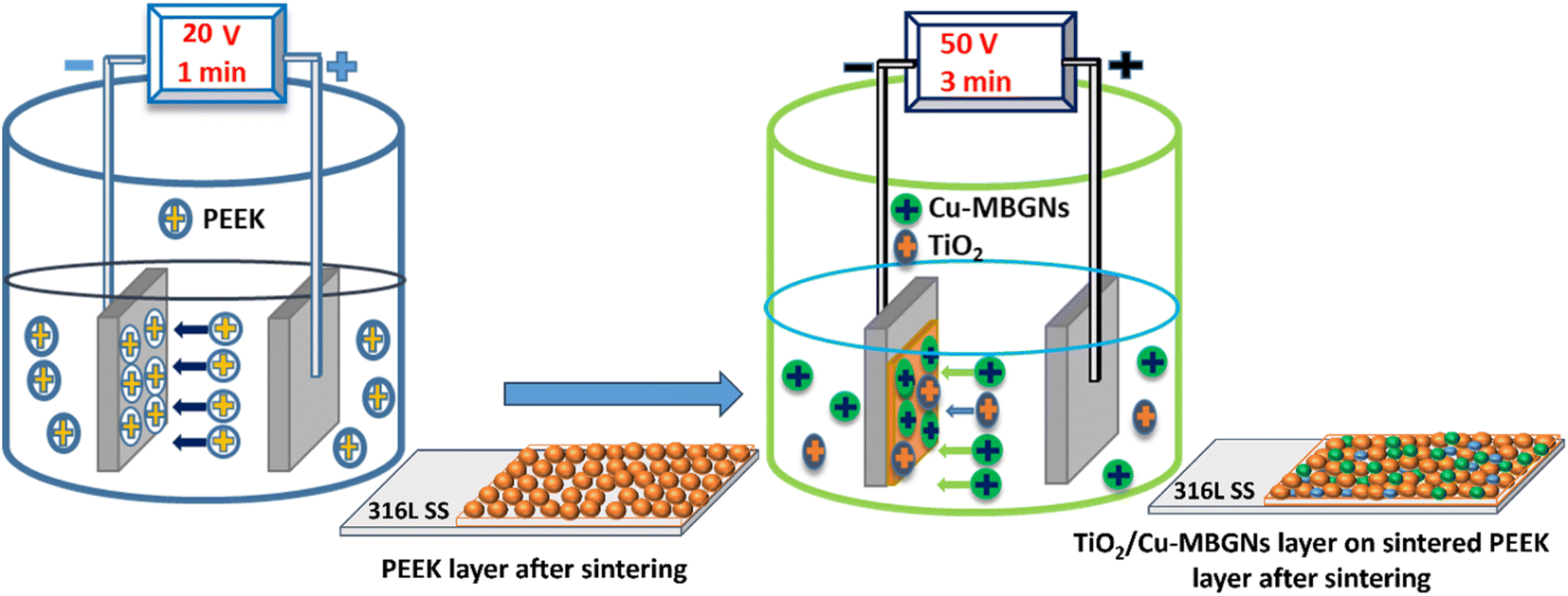 | ||
| Fig. 1 Schematic of deposition and sintering steps of the PEEK layer and TiO2/Cu-MBGN layer on 316L SS via EPD. | ||
The sintering temperature was selected because of the trial-error approach. The bilayer composite coating samples were subjected to various characterization techniques, including scanning electron microscopy (SEM/EDS); Fourier transform infrared spectroscopy (FTIR); surface properties in terms of surface roughness and contact angle; adhesion strength; biological studies in terms of antibacterial activity and cellular study; and wear and corrosion analysis.
2.3. Characterization of bilayer composite coating
000 rpm for 10–12 min at 2–8 °C, and the supernatant was transferred to the well plate with coated capture antibody (Ab), followed by static incubation for 90 min. Similarly, the standard given was also diluted in different concentrations and added to the wells. The reagents, such as a biotin-labelled antibody, mean specific antibody binding capacity (SABC), and tumour mutational burden (TMB), were added and incubated per the manufacturer's instruction, followed by absorbance measurements at a wavelength of 450 nm. The concentration of ALP release from hFOB 1.19 cells co-cultured with uncoated and coated cells was calculated by comparing it with the standard curve.51
 | (1) |
3. Results and discussion
3.1. Mechanism of EPD
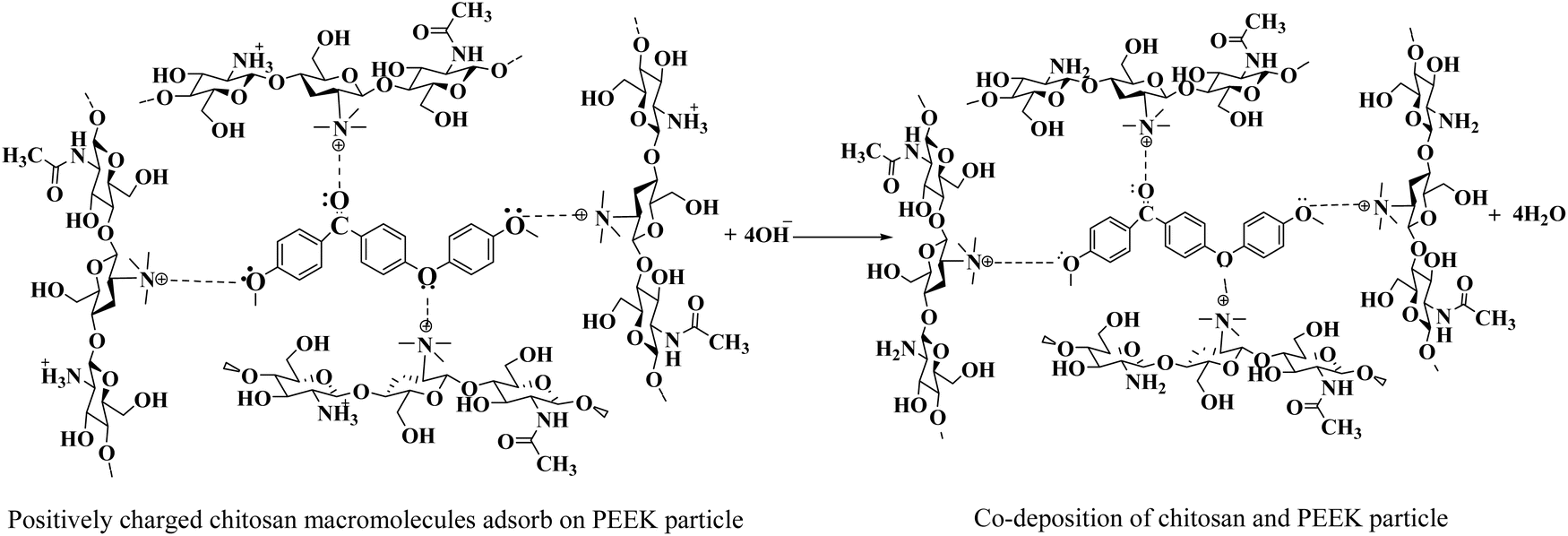
The layers of the PEEK and TiO2/Cu-MBGNs were deposited on 316L SS via EPD. However, a 0.5 g L−1 chitosan solution was used as a binder to deposit these coatings. The existing literature reported the deposition of chitosan with ceramic particles (hydroxyapatite, alumina, titania, metallic ion-doped bioactive glass, and bioactive glass) as co-deposition on 316L SS via EPD.36,47–49,52 Chitosan is insoluble in water, but it is soluble in a solution of distilled water, acetic acid, and ethanol, as reported in ref. 14 and 53 because the amine groups of chitosan are protonated (become positively charged) at low pH ∼4–5. The dissociation reaction of acetic acid and protonation reaction of chitosan according to reactions (2) and (3):| CH3COOH + H2O → CH3COO− + H3O+ | (2) |
| Chitosan–NH2 + H3O → Chitosan–NH3+ + H2O | (3) |
These positively charged macromolecules of chitosan were forced to move toward the cathode as the potential was applied,18,54 but the reduction reactions of water and oxygen occurred at the cathode by reactions (4) and (5):55,56
| 2H2O + 2e− → H2 + 2OH− | (4) |
| O2 + 2H2O + 4e− → 4OH− | (5) |
As reactions (4) and (5) occurred at the cathode, the pH increased, and positively charged macromolecules of chitosan lost their charge and were deposited on the cathode as an insoluble material according to reaction (6):
| Chitosan–NH3+ + OH− → Chitosan–NH2 + H2O | (6) |
Because previous studies have demonstrated that chitosan can be used to deposit inorganic materials on metallic substrates as co-deposition,57–60 the positively charged chitosan macromolecules were used to deposit the PEEK particles when the PEEK suspension was prepared in the 0.5 g L−1 chitosan solution by magnetic stirring and ultrasonication. These positively charged macromolecules of chitosan are adsorbed on the surface of PEEK particles by imparting a net positive charge.58 These positively charged PEEK particles were deposited on the cathode (316L SS) when 20 V with a deposition time of 1 min was applied. Eqn (7) shows the proposed reaction of chitosan and peek particles (co-deposition) on 316L SS. The interaction between the positively charged macromolecules of chitosan and PEEK particles was physical.
 | (7) |
After PEEK particle deposition, the coating was subjected to sintering at 350 °C for 30 min at a 10 °C min−1 heating rate. After the sintering process, the chitosan was evaporated, and only PEEK particles were deposited on 316L SS. The proposed reaction of PEEK particles surrounded by chitosan macromolecules after sintering at 350 °C for 30 min is shown in eqn (8):
 | (8) |
Cu-MBGN particles were positively charged in the ethanol solution and were deposited on the cathode (316L SS) along with TiO2 particles.49,61 In the TiO2/Cu-MBGN suspension in ethanol, acetic acid was added to adjust the pH of the suspension. At pH ranging from ∼3 to 4 of the ethanol and acetic acid suspension, the protonation reactions occurred between the acetic acid and Cu-MBGNs because the silanol group (–Si–OH) at the surface of the Cu-MBGNs was protonated based on reactions (9) and (10):49,62,63
| –Si–O–Cu2+ + CH3COO− + H+ → –Si–OH–Cu2+ + CH3COO− | (9) |
| –Si–OH–Cu2+ + H+ → –Si–OH2+–Cu2+ | (10) |
The protonated silanol group (–Si–OH2+–Cu2+) was forced to move toward the cathode to deposit when a potential of 50 V with a 3 min deposition time was applied to the TiO2/Cu-MBGN suspension. It can be assumed that when the protonated silanol group reaches the cathode surface, oxygen or water reduction reactions (4) and (5) might produce hydrogen gas or hydroxyl ions. This protonated silanol group lost its positive charge and was deposited as a neutral silanol group (Si–OH) on 316L SS.64 Similarly, as in the suspension of TiO2/Cu-MBGNs, TiO2 particles were also deposited with Cu-MBGNs on sintered PEEK coating at 50 V with a deposition time of 3 min. TiO2 particles were also positively charged in the ethanol and acetic acid suspension, with pH ranging from ∼3 to 4. A previous study also reported that TiO2 particles were positively charged in ethanol and acetic-based suspension and deposited at ∼50 V with 3 min of deposition time.48
3.2. SEM analysis of PEEK coating and bilayer composite coating
The morphological analysis of the PEEK layer was deposited at 20 V with a deposition time of 1 min on 316L SS and then sintered at 350 °C for 30 min. A bilayer composite coating was deposited at 50 V with a deposition time of 3 min on a sintered PEEK coating. SEM images of the PEEK layer and bilayer composite coating are shown in Fig. 2 and 3, respectively. The SEM image in Fig. 2A PEEK layer at a magnification of 500× shows the uniform morphology of the PEEK layer all over the surface of the 316L SS substrate without any discernible cracks. However, numerous micro voids were observed in the morphology of the PEEK layer at closer observation of Fig. 2B at a magnification of 1000×. The overall morphology of the PEEK layer is also consistent with the schematic diagram (Fig. 1). However, Fig. 2C at a magnification of 1000× shows that the thickness of the PEEK layer is ∼33 μm.65 The morphological results of the PEEK layer are consistent with earlier findings reported by Corni et al.65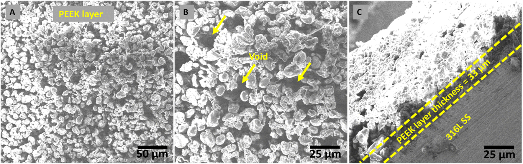 | ||
| Fig. 2 Morphology of a PEEK layer deposited at 20 V and 1 min, followed by sintering at 350 °C. (A) Shows the morphology of PEEK layer deposited on 316L SS via EPD, (B) shows the voids present in PEEK layer, and (C) shows the thickness of PEEK layer. | ||
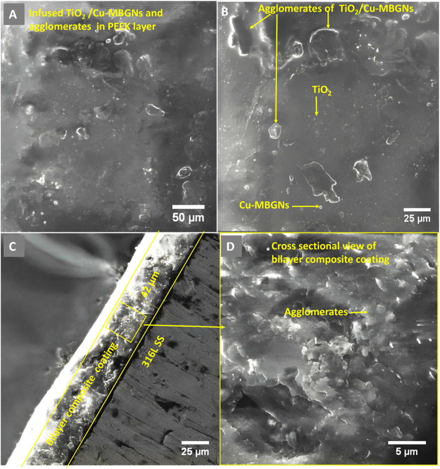 | ||
| Fig. 3 SEM images of the coating produced at 50 V, 3 min: (A) low magnification showing the deposition of coating; (B) high magnification showing the distribution of TiO2/Cu-MBGNs particles on the PEEK layer; (C) cross-section showing coating thickness; and (D) morphology of cross-section of bilayer composite coating. | ||
Fig. 3 shows the SEM images (A and B) at a magnification of 1000× of bilayer composite coating, with smooth and compacted morphology without any discernible pores, micro voids, or cracks in the bilayer composite coating compared to the PEEK layer (Fig. 2). Fig. 3B at 1000× also shows the preferential adhesion and agglomerates/clustering of TiO2 and Cu-MBGNs at specific areas of the bilayer composite coating, which can be attributed to differences in wettability or interfacial interaction between the PEEK layer and TiO2/Cu-MBGN particles. Baştan et al.52 reported a morphology similar to the co-deposition of PEEK/HA composite coating. Fig. 1 schematically shows the deposition mechanisms (3.1 Mechanism of EPD) of both layers and their purposed reactions (2–10) involved in deposition, which constituted the bilayer composite coating. Furthermore, the SEM images (Fig. 3A and B) of the bilayer composite coating revealed a remarkable improvement in the microstructure of the bilayer composite coating by depositing the TiO2/Cu-MBGNs layer on the PEEK layer.
Fig. 3C at a magnification of (1250×) showed the image at the cross-section of the bilayer composite coating, which revealed a coating thickness of ∼42 μm (deposition parameters: 50 V cm−1 and 3 min), while the previous study of the co-deposition of PEEK/HA coating exhibited ∼70 μm.52 The difference in coating thickness between bilayer composite coating and co-deposition was significant because, after deposition of the TiO2/Cu-MBGN layer on the sintered PEEK layer, both layers were sintered at the same parameters, resulting in compacting both layers and reduced coating thickness, which was lower than previous studies reported.32,35,49,66,67
Fig. 3D at (2000×) shows the high magnification at the cross-sectional morphology of the bilayer composite coating, which demonstrates that the coating is densely packed. A similar coating thickness for the PEEK-based composite coating was reported in ref. 44 and 52. It is important to note that the interface between the two layers was not distinguished. This could be because the maximum roughness of the PEEK coating (first layer) is ∼10 μm. Thus, the top layer usually infiltrates the bottom layer. Therefore, a clear interface for a PEEK-based multilayer coating cannot be observed. A similar effect was reported in ref. 28, 29 and 31.
Furthermore, it was hypothesized that upon sintering both layers, the bottom PEEK layer melted (because the melting point of PEEK is 343 °C). Thus, the TiO2/Cu-MBGNs on the top layer were wetted by the melted PEEK layer, and upon cooling, the TiO2 and Cu-MBGNs became trapped in the PEEK layer. These particles acted as reinforcements in the PEEK matrix, thus resulting in excellent adhesion strength. Furthermore, excellent compaction/densification of both layers upon sintering resulted in improved wear- and corrosion-resistance. Similar findings about the strengthening mechanism of PEEK-based composite coatings deposited on 316L SS were reported in previous studies.32,49,66,68
3.3. EDS analysis
EDS analysis was performed by SEM equipped with an EDS detector to identify and confirm the presence of TiO2 and Cu-MBGNs in the bilayer composite coating. The EDS results revealed that carbon and silicon belong to PEEK and that Cu-MBGNs are present as primary constituents. Meanwhile, Ca, Ti, and Cu were present in minor amounts because their concentration in the bilayer composite coating was low. Fig. 4 shows the EDS analysis of the bilayer composite coating. | ||
| Fig. 4 EDS analysis of the bilayer composite coating deposited on 316L SS. | ||
Fig. 5 shows the EDS elemental mapping of the bilayer composite coating, which also confirms the presence of TiO2 (Ti detected in EDS mapping) and Cu-MBGNs (Si, Ca, and Cu elements indicate the presence of Cu-MBGNs) infused in the PEEK layer.49
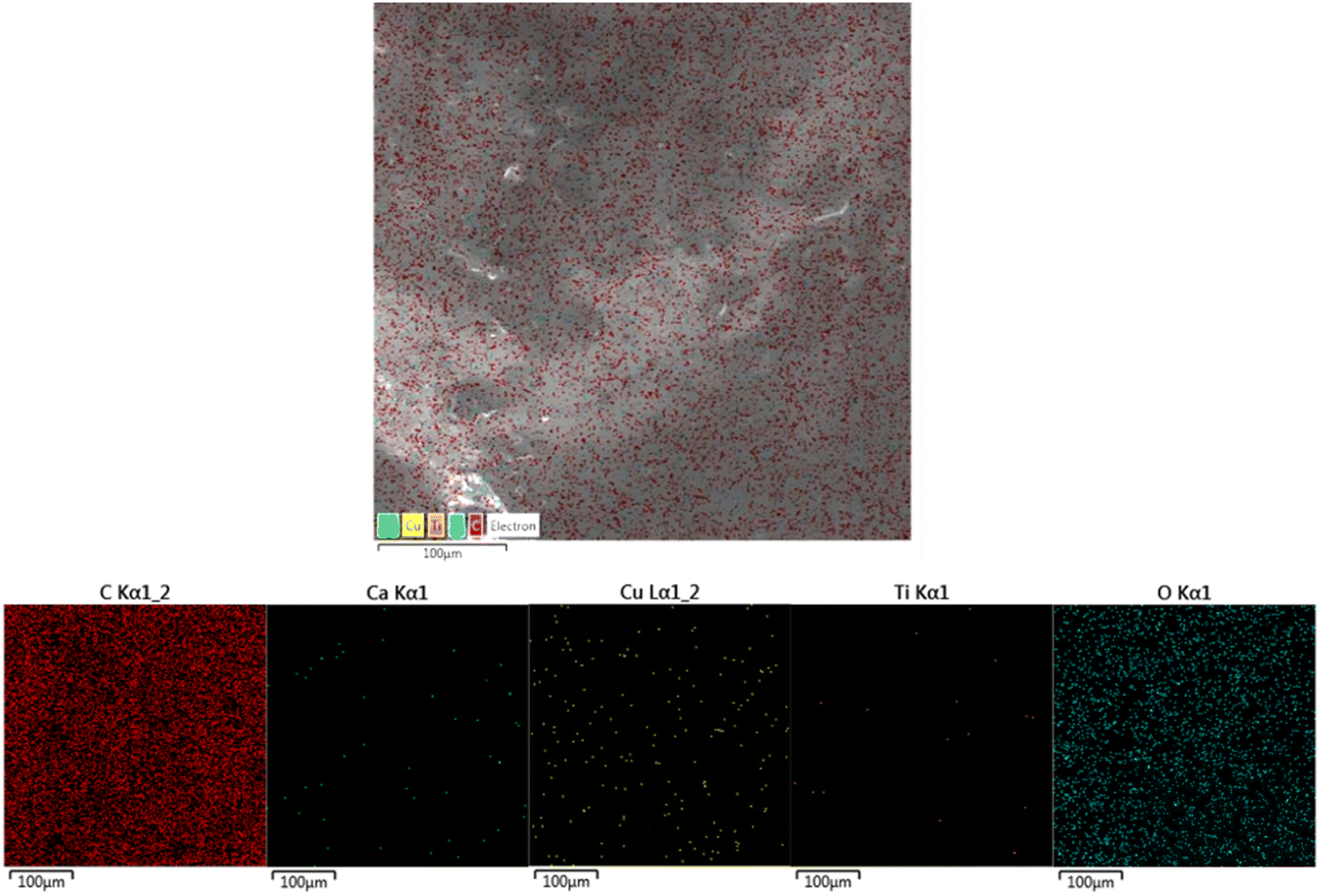 | ||
| Fig. 5 EDS elemental mapping images, which confirms the presence of TiO2/Cu-MBGNs in the bilayer composite coating. | ||
3.4. Identification of functional groups
The ATR-FTIR spectra of PEEK, Cu-MBGNs, and TiO2 are presented in Fig. 6A, while the spectrum of the bilayer composite coating is shown in Fig. 6B. The characteristic bands of aromatic rings (C–H) in PEEK were identified at 762, 834, and 924 cm−1.52 The typical carbonyl (C![[double bond, length as m-dash]](https://www.rsc.org/images/entities/char_e001.gif) O) stretching band and C–O–C in PEEK were detected at 1648 and 1006 cm−1, respectively.61 Furthermore, a band associated with the angular deformation of the C–H bond was visible at 1590 cm−1.69 The FTIR spectrum of the Cu-MBGNs showed two bands at 440 cm−1 and 812 cm−1, which are attributed to Si–O–Si bending and symmetric stretching vibrations, respectively. The bands of asymmetric Si–O–Si (bridging bonds) and Si–O (non-bridging bonds) vibrations were observed in the range of 1299–900 cm−1.26,70 The appearance of these bands shows that tetrahedrons are formed to create a glass network of particles. The band associated with the phosphate group of MBGNs appeared at 600 cm−1.71 The band at 545 cm−1 corresponded to the presence of Cu–O in Cu-MBGNs.26 The presence of TiO2 in the composite coatings was illustrated by the characteristic band at 418 cm−1 and 482 cm−1, which is related to the bending and stretching modes of Ti–O–Ti, respectively.72 ATR-FTIR spectroscopy also revealed characteristic bands corresponding to the functional groups of the bilayer composite coating. The formation of a layer with a suspension containing TiO2 and Cu-MBGNs over the PEEK-coated substrate was confirmed by FTIR. The carbonyl group of PEEK particles interacted with the hydrogen ions of suspensions containing water, ethanol, and acetic acid, forming weak dipole–dipole interactions. The appearance of a new band at 1738 cm−1 corresponded to the aldehyde carbonyl group involved in forming interactions between bilayers,73 as shown in Fig. 6B. This can further be confirmed by the broadening and increased intensity of Ti–O–Ti, Cu–O (shifted to 595 cm−1), and Si–O–Si symmetric stretching vibration bands. Additionally, the slight shift in the band position of C–O–C confirmed the formation of a bilayer composite coating. The bands at 812 and 595 cm−1 were attributed to Si–O–Si symmetric stretching vibrations and Cu–O, respectively, of Cu-MBGNs.26,70 The appearance of a broadened and increased intensity band at 482 cm−1 corresponded to Ti–O–Ti, Si–O, and PEEK.26,70,72 The typical carbonyl (CO) stretching band and C–O–C in PEEK were detected at 1648 and 1006 cm−1, respectively.61 Table 1 summarises all bands in PEEK, Cu-MBGNs, TiO2, and coating deposited on 316L SS via EPD. The possible interaction after sintering at 350 °C between the sintered PEEK layer and TiO2/Cu-MBGNs layer is shown in Fig. 7.
O) stretching band and C–O–C in PEEK were detected at 1648 and 1006 cm−1, respectively.61 Furthermore, a band associated with the angular deformation of the C–H bond was visible at 1590 cm−1.69 The FTIR spectrum of the Cu-MBGNs showed two bands at 440 cm−1 and 812 cm−1, which are attributed to Si–O–Si bending and symmetric stretching vibrations, respectively. The bands of asymmetric Si–O–Si (bridging bonds) and Si–O (non-bridging bonds) vibrations were observed in the range of 1299–900 cm−1.26,70 The appearance of these bands shows that tetrahedrons are formed to create a glass network of particles. The band associated with the phosphate group of MBGNs appeared at 600 cm−1.71 The band at 545 cm−1 corresponded to the presence of Cu–O in Cu-MBGNs.26 The presence of TiO2 in the composite coatings was illustrated by the characteristic band at 418 cm−1 and 482 cm−1, which is related to the bending and stretching modes of Ti–O–Ti, respectively.72 ATR-FTIR spectroscopy also revealed characteristic bands corresponding to the functional groups of the bilayer composite coating. The formation of a layer with a suspension containing TiO2 and Cu-MBGNs over the PEEK-coated substrate was confirmed by FTIR. The carbonyl group of PEEK particles interacted with the hydrogen ions of suspensions containing water, ethanol, and acetic acid, forming weak dipole–dipole interactions. The appearance of a new band at 1738 cm−1 corresponded to the aldehyde carbonyl group involved in forming interactions between bilayers,73 as shown in Fig. 6B. This can further be confirmed by the broadening and increased intensity of Ti–O–Ti, Cu–O (shifted to 595 cm−1), and Si–O–Si symmetric stretching vibration bands. Additionally, the slight shift in the band position of C–O–C confirmed the formation of a bilayer composite coating. The bands at 812 and 595 cm−1 were attributed to Si–O–Si symmetric stretching vibrations and Cu–O, respectively, of Cu-MBGNs.26,70 The appearance of a broadened and increased intensity band at 482 cm−1 corresponded to Ti–O–Ti, Si–O, and PEEK.26,70,72 The typical carbonyl (CO) stretching band and C–O–C in PEEK were detected at 1648 and 1006 cm−1, respectively.61 Table 1 summarises all bands in PEEK, Cu-MBGNs, TiO2, and coating deposited on 316L SS via EPD. The possible interaction after sintering at 350 °C between the sintered PEEK layer and TiO2/Cu-MBGNs layer is shown in Fig. 7.
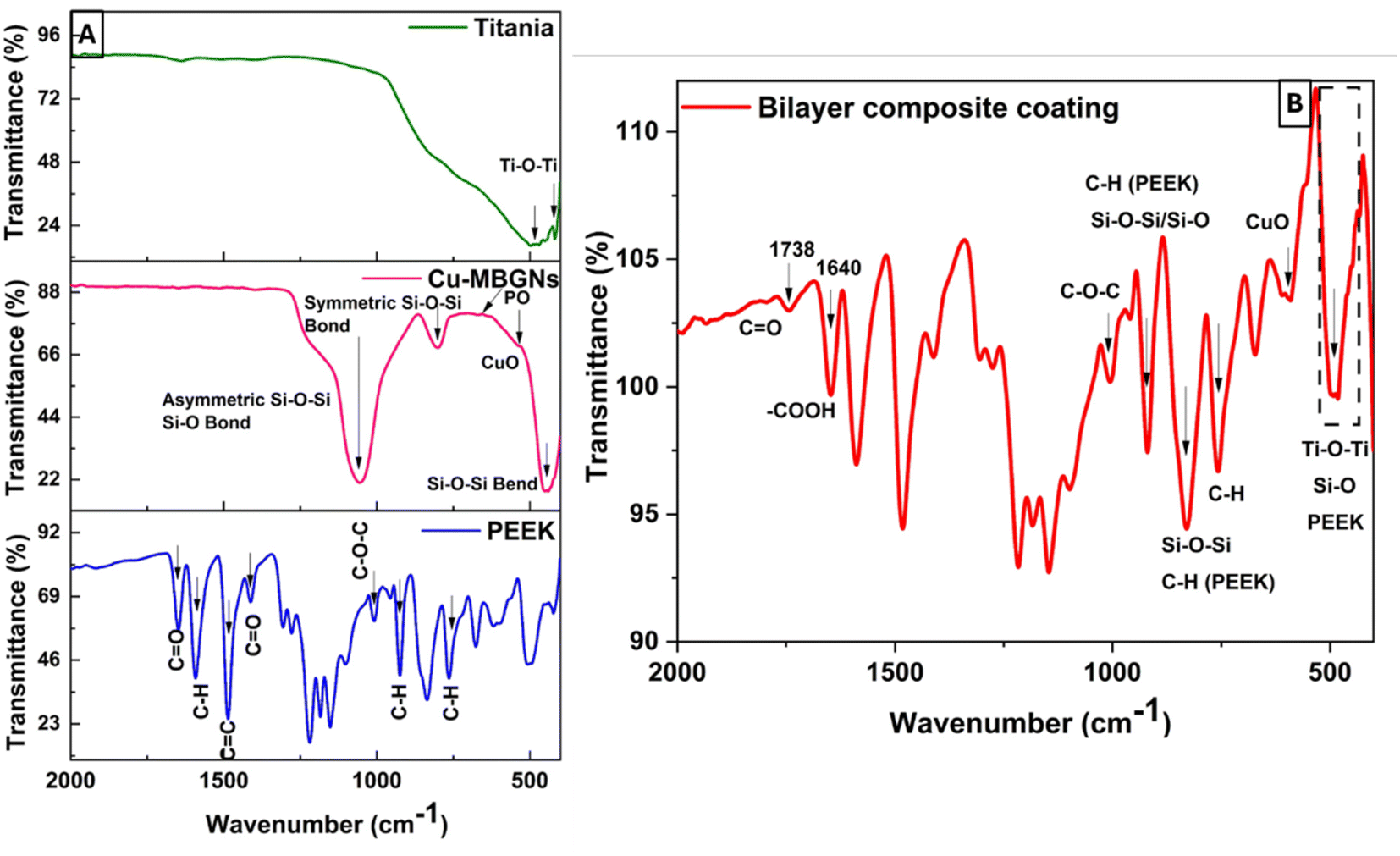 | ||
| Fig. 6 FTIR spectra of (A) PEEK, Cu-MBGNs, TiO2, and (B) bilayer composite coating. | ||
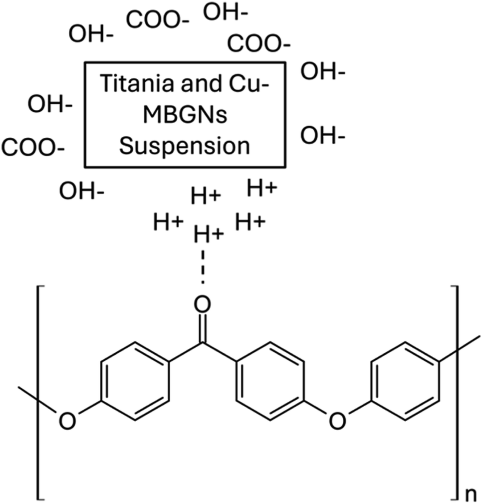 | ||
| Fig. 7 Possible interactions between the sintered PEEK layer and TiO2/Cu-MBGN layer. | ||
3.5. Thermogravimetric analysis
The TGA thermogram of the bilayer composite coating showed three distinct degradation steps, as shown in Fig. 8. The first degradation step occurred between 478 and 700 °C, resulting in 35% weight loss, primarily attributed to the degradation of PEEK.74 Thus, sintering was done at 350 °C.75 The subsequent degradation steps occurred within the temperature range of 700–770 °C, which is accompanied by a weight loss of 6%.76 This weight loss corresponded to the degradation of organic compounds, CTAB, and unreacted nitrates. The low weight loss reflected the high thermal stability of the Cu-MBGNs, which limited the degradation process. As discussed in the FTIR section, the increased degradation temperature can be attributed to the weak interaction between PEEK and Cu-MBGNs. Notably, the degradation of titania was not observed up to 900 °C, confirming its high thermal stability.77 The char yield was ∼20%, indicating the percentage of non-degraded TiO2 and Cu-MBGNs.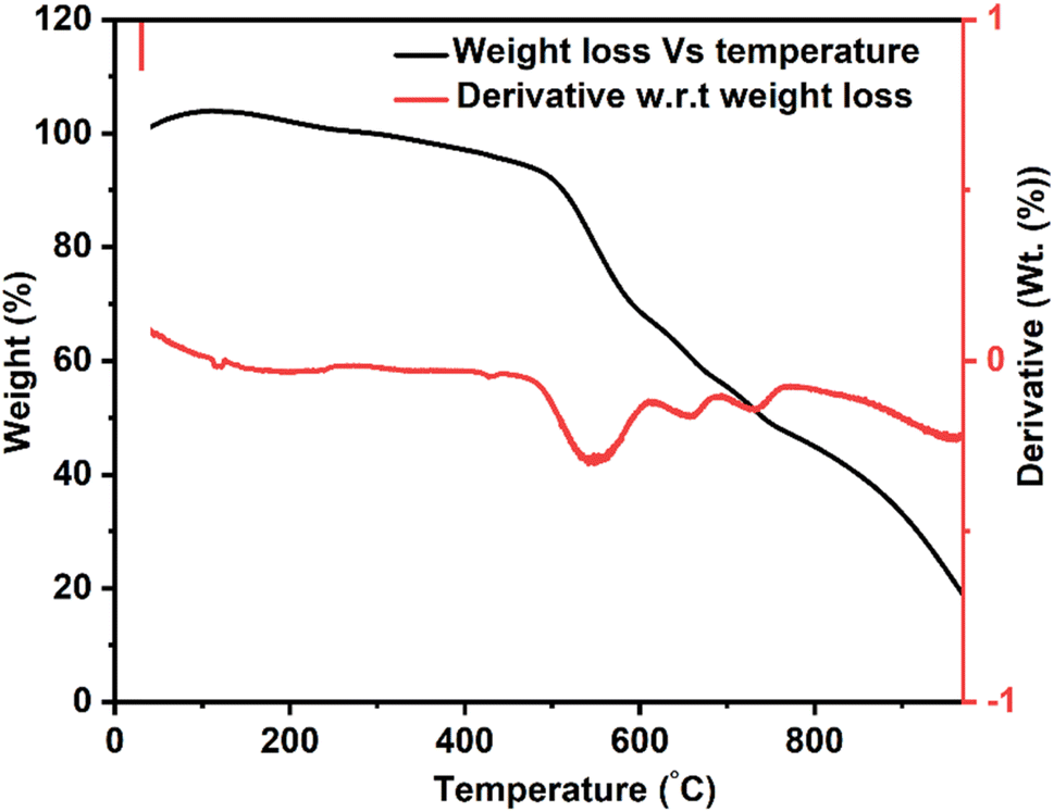 | ||
| Fig. 8 TGA thermogram for bilayer composite coating. | ||
The TGA result of bilayer composite coating deposited on 316L SS was in good agreement with previous findings reported in ref. 32, 66 and 78.
3.6. XRD analysis
Fig. 9 shows the XRD pattern of the bilayer composite coating. The XRD pattern exhibited the semicrystalline nature of the coating. The peak at 2θ = 25.7° depicted the presence of CuO and moved towards the higher values of the Bragg angle, as reported elsewhere.79,80 This implies that after sintering, the lattice parameters are expanded and shifted from the angle to higher values. Furthermore, the peaks appeared at 2θ = 43.8°, 54.8°, and 75.1°, confirming the presence of TiO2 (anatase), and these data matched with JCPDS #21-1272. Similarly, findings have been reported in previous studies.81,82 The intensity of the diffraction peak of TiO2 increased after sintering, as shown by the XRD pattern, and the high value of impedance in the EIS spectra, as shown in Fig. 15.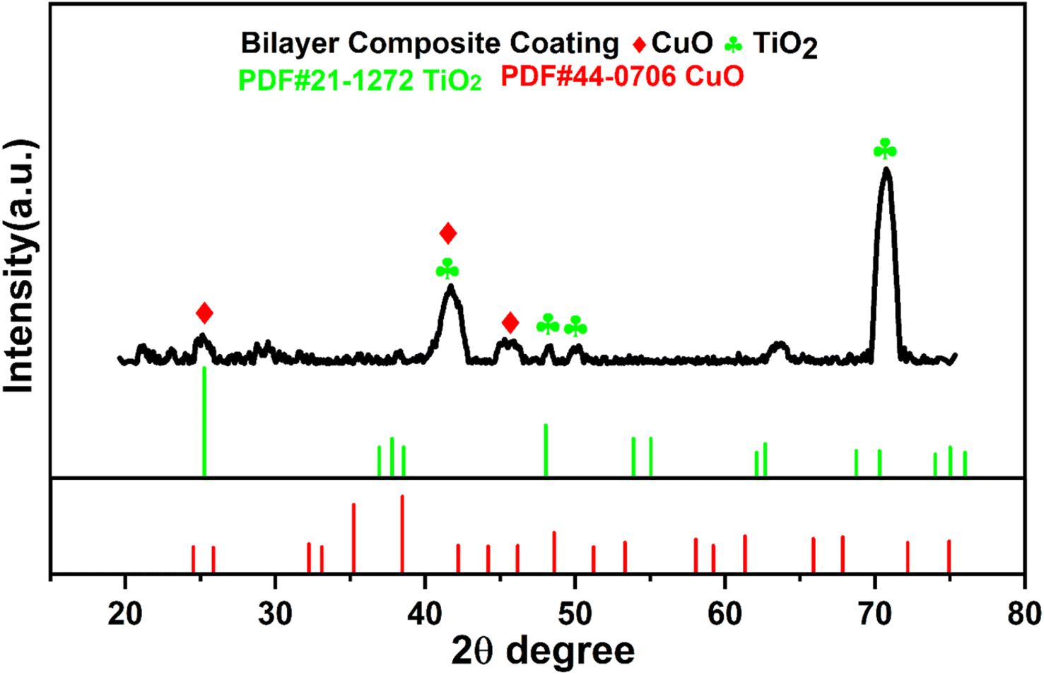 | ||
| Fig. 9 XRD spectrum of bilayer composite coating and relevant indexing and matching of the relevant peaks. | ||
The XRD results agree with the FTIR results, and both results show the presence of TiO2 and Cu-MBGNs in the bilayer composite coating deposited on 316L SS. PEEK is a semicrystalline material83 that serves as a matrix material, while TiO2/Cu-MBGNs are used as reinforcing agents in bilayer composite coatings. The XRD spectrum showed distinct peaks belonging to TiO2, and Cu-MBGNs confirmed the presence of these crystalline phases in the bilayer composite coating. However, these distinct peaks associated with TiO2 and Cu-MBGNs were relatively broad peak widths with lower intensities compared to fully crystalline material, suggesting the semicrystalline nature of bilayer composite coating.
3.7. Surface properties
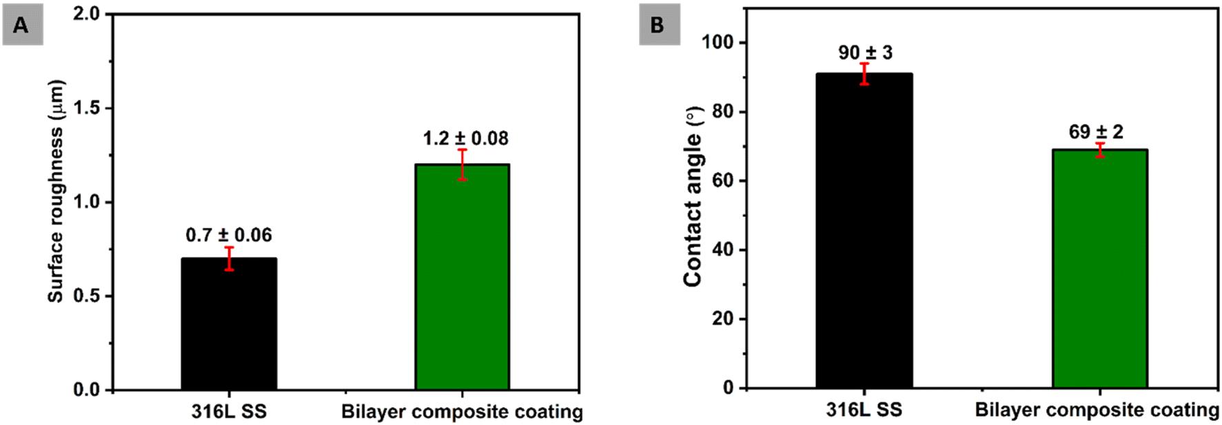
Surface properties, such as surface roughness and wettability, are essential in the context of preventing biofilm formation and facilitating the attachment of osteoblast cells.84 The uncoated 316L SS substrate was used as the reference sample. Surface roughness is the most critical factor in implant surfaces due to its direct interaction between microbes and cell attachment. Furthermore, surface roughness affects the performance of an implant. The osteoblast cells favourably attach to the surface with an average roughness of 1–2 μm.61,85 This study measured the average surface roughness (Ra) for bilayer composite coating as 1.20 ± 0.08 μm. The Ra value of the bilayer composite coating reported in this study is comparable with that reported in ref. 50 and 35. The Ra of bilayer composite coatings is less than that of PEEK coating deposited on 316L SS (the Ra value for PEEK was taken from our previous study86), which could be attributed to the difference in particle size and coating thickness.Furthermore, the top layer may have infiltrated the bottom PEEK layer. The bilayer composite coating was subjected to sintering (as described in Subsection 2.2), which may have resulted in further compactness of the coating and infiltration of TiO2 and Cu-MBGNs in the pores of the PEEK layer. The relatively higher value of average roughness of the bilayer composite coating compared to that of the 316L SS can induce better adhesion of bone cells and related proteins. It can stimulate the formation of the extracellular matrix.87
The wettability of bilayer composite coating deposited on 316L SS implant is closely related to biological response in the human body.88 The critical protein attachment,89 cell adhesion,90 cell proliferation and behaviour91 to the surface can be adversely affected due to high hydrophobicity or hydrophilicity, which causes complications for bone tissue engineering. Menzies and Jones87 and Arias et al.92 reported that the ideal values of the contact angle for bone tissue application is between 35° and 80°. The measurement of the contact angles of 316L SS and bilayer composite coating are 90° ± 3° and 69° ± 2°, respectively. This value of the contact angle of bilayer composite coating is in good agreement with the accepted range of contact angles necessary for biological response.92 Furthermore, the contact angle value of the bilayer composite is slightly different from previously reported values of contact angles31,52,92 because of the difference in the composition of the bilayer composite coating. The moderately hydrophilic behavior of the bilayer composite coating is attributed to the TiO2 and Cu-MBGNs. The TiO2 is hydrophilic in nature,93 while the Cu-MBGNs contain silanol groups (Si–OH, which is formed due to the hydration of siloxane bond (Si–O–Si) on the surface of MBGNs), which are also hydrophilic. The synergistic effect of TiO2/Cu-MBGNs caused the contact angle of bilayer composite coating to decrease.
Fig. 10 shows a comparison between the surface properties of the 316L SS and bilayer composite coating. Therefore, the bilayer composite coating exhibited moderately hydrophilic behavior, which can assist in the initial protein attachment and subsequent proliferation of bone-forming cells.84
 | ||
| Fig. 10 (A) Comparison of surface roughness of bilayer composite coating with 316L SS and (B) comparison between contact angles of bilayer composite coating and 316L SS. | ||
The surface topography of bilayer composite coating can impact wettability. Thus, rougher surfaces would improve wettability due to the enhanced contact sites between the water and the surface. The hydrophilic nature of the coating can prevent protein denaturation. Thus, a contact angle of 69° ± 2° can be considered suitable for osseo-integration.
3.8. Bend test
The adhesion strength of the bilayer composite coating deposited on the 316L SS substrate was determined by a bend test, as shown in Fig. 11. The bilayer composite-coated sample was manually bent at 180°, and stereomicroscope images showed no discernible cracks in the bilayer composite coating or delamination of the coating at the centre or edges of the bilayer composite coating (Fig. 11). The bending test result was evaluated according to ASTM standard A1122. The adhesion strength of the coating was rated as ‘5B’.36 The bending strength of the bilayer composite coating confirmed the excellent adhesion strength and resistance to deformation upon application of the bending load. The bilayer composite coating did not exhibit cracks at the site of the highest stress (marked by the blue box in Fig. 11A and B). Similar results for the PEEK-based composite coatings were reported in the literature.36 The excellent adhesion strength is attributed to the carefully selected sintering temperature of the PEEK layer as the first layer and the second layer of TiO2/Cu-MBGNs as reinforcing agents. The appropriate sintering temperature allowed the TiO2 and Cu-MBGN particles to interdiffusion in the PEEK layer. Thus, the bilayer composite coating provided a strengthening effect (resistance plastic deformation) upon applying the bending load.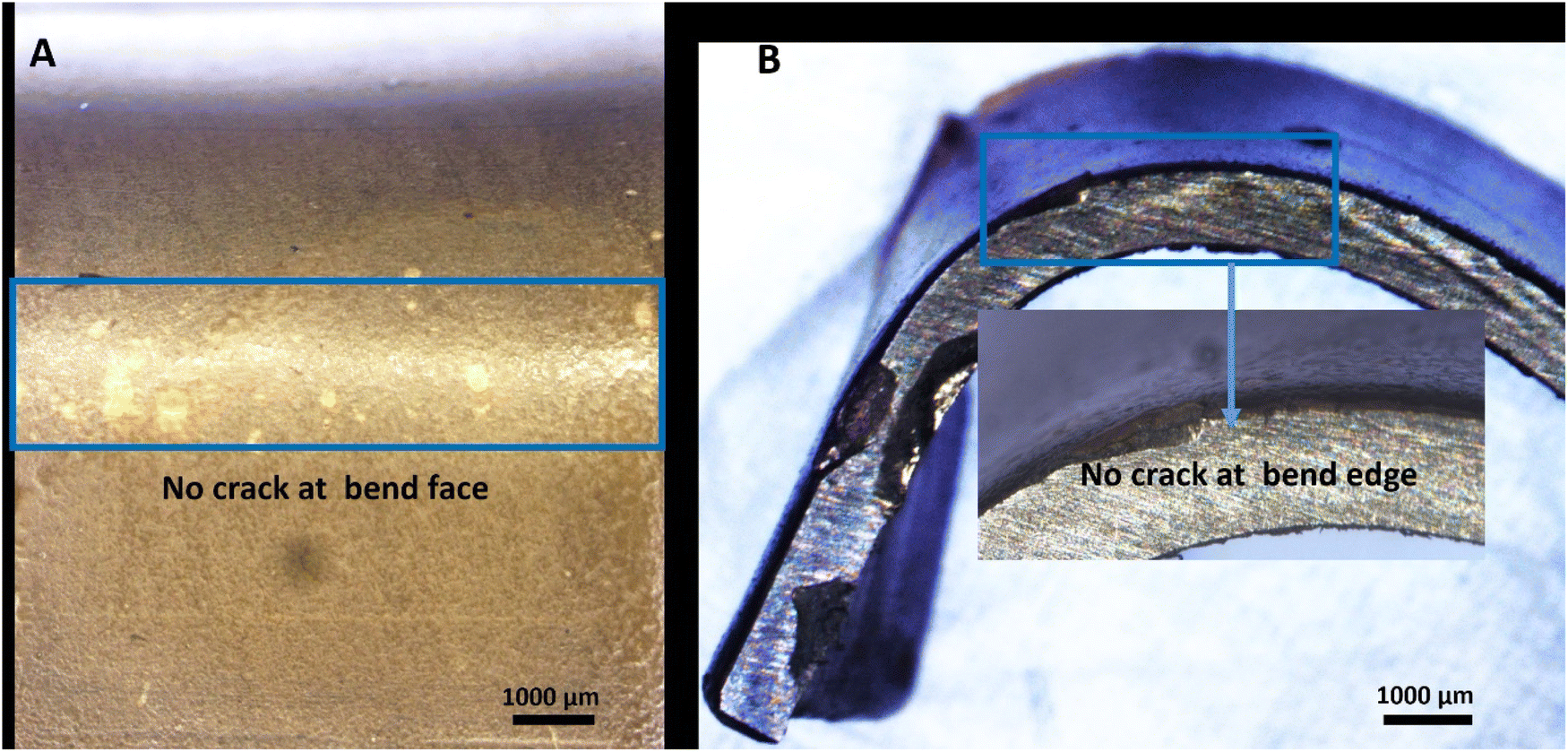 | ||
| Fig. 11 Stereomicroscope images showing the results of the bend test from different angles: (A) concave and (B) convex sides. | ||
The bilayer composite coating was neither delaminated nor cracked at the bend face and edge. The poor adhesion of the PEEK coating is attributed to the inert nature of PEEK, which restricts the bonding between the PEEK and TiO2/Cu-MBGN particles present in the coating. However, in the current study, the coatings exhibited excellent bending strength and adhesion strength. This could be attributed to the mesoporous nature of Cu-MBGNs and nano-sized TiO2 particles, which can create a rough interface with an oxide layer of 316L SS.94 Thus, it induced mechanical interlocking between the bilayer composite coating and 316L SS, which resulted in strong adhesion between bilayer composite coating and 316L SS substrates. Furthermore, previous studies on the PEEK-based composite coatings focused on the surface properties, biological properties, and release kinetics of specific drugs,32,47,48,68,95 but there is a limited study in which the adhesion strength of PEEK-based BG composite coating was evaluated through a bend test.36 The bilayer composite coating showed excellent adhesion strength through the bend test than previously reported in a study.36
3.9. Antibacterial study
The antibacterial activity of the PEEK coating and Cu-MBGNs loaded with the coatings was evaluated against S. aureus and E. coli strains. The PEEK coating was used as a control sample. Images of Petri dishes containing inoculated agar and coatings after 24 h were taken in a blue background to enhance the visibility of zones of inhibition displayed by bilayer composite coating.31,96,97 Fig. 13 shows that the bilayer composite coating exhibited inhibition zones with a radius of 1.9 ± 0.14 cm and 1.56 ± 0.09 cm against (Fig. 12A) S. aureus and (Fig. 12B) E. coli, respectively.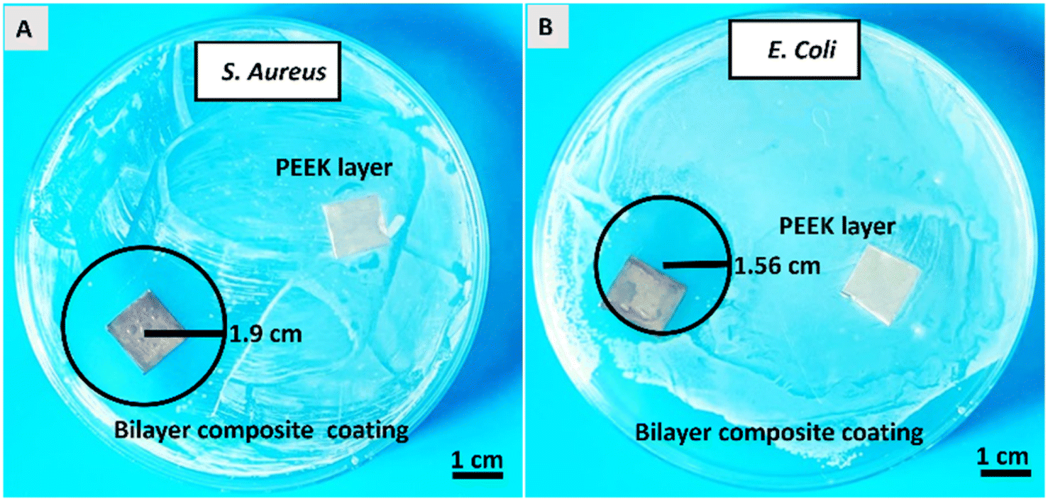 | ||
| Fig. 12 Antibacterial activity of bilayer composite coating against (A) S. aureus and (B) E. coli strains. | ||
The release of Cu2+ ions from bilayer composite coatings is responsible for introducing antimicrobial activity. The S. aureus contains a single lipid bilayer of peptidoglycan (20–80 nm), which becomes attractive to positive charges (as it has negatively charged surface polymers, such as teichuronic and lipoteichoic acids). Thus, the zone of inhibition depended on the action of release of metallic ions, which diffused quickly in the microbial cells due to attraction. This resulted in cell apoptosis through cell membrane disruption and the denaturation of protein.52 E. coli is less attractive towards metallic ions as it has a highly organized compact structure, which acts as a permeability barrier. Ultimately, diffusion is prevented. Thus, the zone of inhibition appeared to be smaller against E. coli. Additionally, Cu2+ tolerance mechanisms in E. coli, such as copper removal by metallothioneins and activation transmembrane Cu2+ export occurring from the cytoplasm into the periplasmic space or the extracellular matrix, can further explain why the inhibition zone was smaller against E. coli than S. aureus.24 Furthermore, the bilayer composite coating demonstrated an improved antibacterial effect against S. aureus and E. coli compared to previous studies conducted on PEEK-based bioactive glass doped with different metallic ions, such as Ag, Mn, lawsone, curcumin (natural herbs), and chitosan incorporated in composite coating.31,32,35,49,98
3.10. Cellular study
To understand the bone formation and mineralization processes in the coated and uncoated samples, the release of a key protein (ALP) in the bone matrix was assessed. The ALP release was significantly higher for the bilayer composite-coated 316L SS than for the 316L SS (as shown in Fig. 13). This may be attributed to the release of bioactive ions and the improved surface topography of 316L SS.99 It is assumed that the Cu-MBGNs incorporated into the bilayer composite coating may have released Cu2+ ions to induce osteogenic activity and ultimately enhance ALP release.100 Cu2+ ions were reported to enhance ALP release by the activation of signalling pathways, such as the Wnt/β-catenin pathway and the mitogen-activated protein kinase (MAPK) pathway.101,102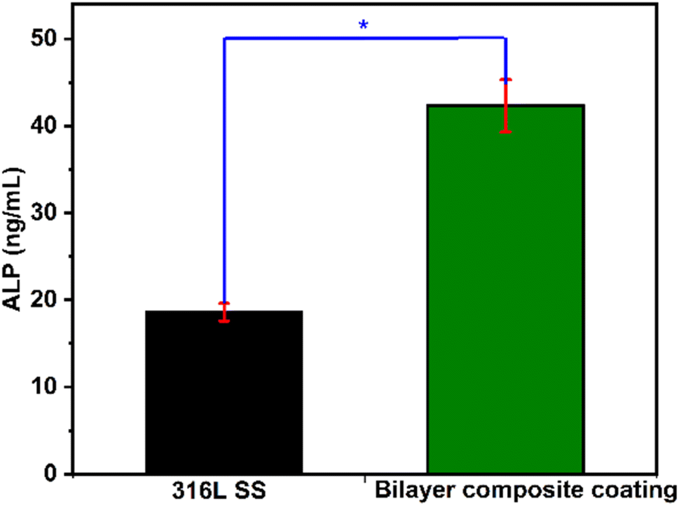 | ||
| Fig. 13 ALP release (ng mL−1) from 316L SS and bilayer composite coated 316L SS, where * shows that the difference between 316L SS and bilayer composite coating is statistically significant at p < 0.05 (data represent ± standard deviation of three samples). | ||
However, the improved surface topography may also influence cell adhesion and differentiation. Cu2+ ions can also inhibit the activity of osteoclast cells by the induction of apoptosis, inhibition of enzymes involved in osteoclast activity (such as cathepsin K), or disruption of the nuclear factor-kappa B (NF-κB) signalling pathway, which is critical for osteoclast formation and function.103,104
3.11. Tribological study
Tribological properties of PEEK coating (thickness ∼66 μm)40 and bilayer composite coating (thickness ∼42 μm) were investigated by a pin-on-disc test conducted under DMEM-lubricated conditions. The tribological properties of bilayer composite coating were compared with PEEK coating (the tribological properties of PEEK coating deposited on 316L SS are described in our previous study40). The effect of the TiO2/Cu-MBGN layer infused into the PEEK layer was studied regarding tribological properties.The PEEK coating with a thickness of ∼66 μm (ref. 40) and bilayer composite coatings were subjected to tribological study at 10 N under DMEM lubricating condition (which is more relevant to physiological conditions). The PEEK coating in the presence of DMEM exhibited instability due to delamination. Thus, the functional integrity of the PEEK coating under physiological conditions cannot be established due to delamination and negative CoF. However, the bilayer composite coating exhibited stable behaviour throughout the sliding distance. The CoF of the bilayer composite coating remained constant at ∼0.032 in the presence of DMEM throughout the sliding distance. CoF behaviour confirmed that bilayer composite coating is wear-resistant and, thus, suitable for orthopedic applications.
The CoF of bilayer composite coating decreased under DMEM lubricating conditions compared to that of the CoF of bilayer composite coating under dry sliding conditions. The CoF of bilayer composite coating was reduced under DMEM lubricating conditions due to decreased friction between bilayer composite coating and counter surface.105 There is a possibility that DMEM molecules can migrate to the bilayer composite coating surface and form a thin layer that acts as a lubricant. DMEM molecules can also penetrate minor grooves and scratches on bilayer composite coating, which reduces the roughness of the surface and leads to a decrease in the CoF of bilayer composite coating. Furthermore, DMEM solution can wet the surface of bilayer composite coating, producing a thin film of lubricant, thus reducing the friction between bilayer composite coating and counter surface. The results of tribological tests of PEEK and bilayer composite coatings in DMEM are expressed in terms of CoF vs. sliding distance (Fig. 14A). Fig. 14B shows a comparison between the specific wear rates, and Fig. 14C shows the SEM image of the wear track.
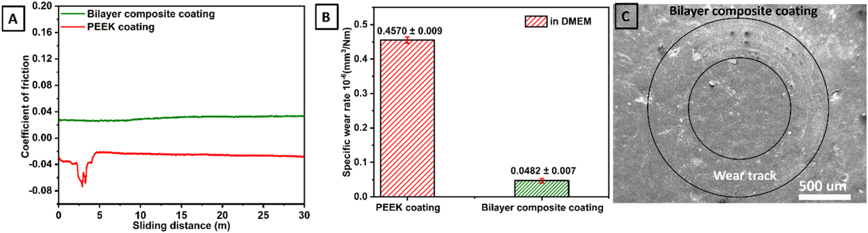 | ||
| Fig. 14 (A) CoF measured as a function of sliding distance for both PEEK and bilayer composite coatings under wet conditions, i.e., in the presence of DMEM, (B) comparison between specific wear rates and (C) SEM image of wear track of bilayer composite coating. | ||
The specific wear rates of PEEK and bilayer composite coatings were also determined under DMEM lubricating conditions. In DMEM, the bilayer composite coating (Fig. 14B) showed better results than the PEEK coating. The specific wear rate of bilayer composite coating was (0.0482 ± 0.007) × 10−6 mm3 Nm−1, while PEEK coating showed a particular rate of wear of (0.4570 ± 0.009) × 10−6 mm3 Nm−1, indicating that PEEK coating delaminated from 316L SS in the presence of DMEM (Table 2). It can be assumed that the DMEM is a cell culture media that contains high concentrations of various ions (Na+, K+, Ca2+, Mg+, Cl− and PO43−) and solutes (amino acids, glucose, salts, vitamins, hormones, and growth factors). Owing to the semi-crystalline nature of PEEK, it may be susceptible to hydrolytic degradation.106 This may lead to the breakdown of the polymer chain, which results in the formation of cracks and fissures in the PEEK coating during tribological tests. These cracks and crevices can provide pathways for DMEM to penetrate the coating. This penetrated DMEM can attack the underlying 316L SS and lead to the delamination of the PEEK coating from 316L SS.40,107 In the tribology test, sliding contact could lead to wear mechanisms, such as abrasion and adhesion, which gradually delaminated the PEEK coating in the presence of DMEM.
| Condition | Coating | Applied | Accumulative wear | Specific wear rate | Average |
|---|---|---|---|---|---|
| Load (N) | Volume (mm3) | (×10−6 mm3 N−1 m−1) | CoF | ||
| DMEM | PEEK coating | 10 | 137.10 ± 0.06 | 0.4570 ± 0.009 | 0.0758 |
| Bilayer composite coating | 10 | 14.46 ± 0.02 | 0.0482 ± 0.007 | 0.0302 |
Fig. 14C shows the SEM image of the wear track belonging to bilayer composite coating where the coating did not delaminate after pin on disc test conducted under 10 N applied normal load in the presence of DMEM. In the bilayer composite coating, TiO2 and Cu-MBGNs in the top layer reinforced the PEEK layer upon sintering. This improves the mechanical properties such as resistance to delamination and wear under dry and DMEM lubricating conditions. The compact TiO2/Cu-MBGNs layer infused in the PEEK layer acts as a barrier between the DMEM and 316L SS. Thus, DMEM could not penetrate the underlying 316L SS, which further reduced the risk of delamination of the bilayer composite coating. Table 2 illustrates the performance of PEEK and bilayer composite coatings under wet conditions.
This strong adhesion strength of the bilayer composite coating may be attributed to the following mechanisms. After SEM analysis of the bilayer composite coating at the surface, the morphology and topography showed that TiO2/Cu-MBGNs were uniformly distributed, and clusters of these particles were observed at specific sites. Furthermore, porosity or micro voids were not present in the bilayer composite coating. Similarly, the cross-section of bilayer composite coating, with a thickness of ∼42 μm, was also mapped to observe the diffusion of TiO2/Cu-MBGNs in the PEEK layer after sintering at 350 °C. It can be assumed that even the PEEK might be decomposed at sintering temperature, while the residual carbon might form a strong bond with a protective oxide layer of 316L SS. The TiO2/Cu-MBGNs present on the sintered PEEK layer might react with this residual carbon. Furthermore, the sintering of the TiO2/Cu-MBGNs layer deposited on the sintered PEEK layer resulted in melting and fusion at the interface between PEEK particles and TiO2/Cu-MBGNs because the sintering created a porous and rough surface on the PEEK layer, where these TiO2/Cu-MBGNs penetrated pores of the PEEK layer. The TiO2/Cu-MBGNs were embedded in a PEEK layer and acted as reinforcing materials in the bilayer composite coating, resulting in a mechanically interlocked structure between the PEEK layer and TiO2/Cu-MBGNs layer, which prevented the delamination of the bilayer composite coating by anchoring these TiO2/Cu-MBGNs firmly in the PEEK matrix. Thus, it was concluded that the surface largely consisted of PEEK with particles of TiO2/Cu-MBGNs embedded in the bilayer composite coating system (which supports the proposed strengthening mechanism in the current study).108
3.12. Electrochemical studies
EIS measurements were conducted of all bare 316L SS and bilayer composite coating after 1 h and 24 h of immersion in PBS at 37 ± 1 °C, as shown in Fig. 15. The EIS data were analyzed, and the results were displayed in Nyquist and Bode plots. The EIS data were also subjected to fitting in ZSimpWin software with an appropriate electrical equivalent circuit to determine the values of the relevant parameters. Nyquist plot, which is a graphical representation of electrical behavior in terms of impedance, was plotted between real impedance at the x-axis and imaginary impedance at the y-axis.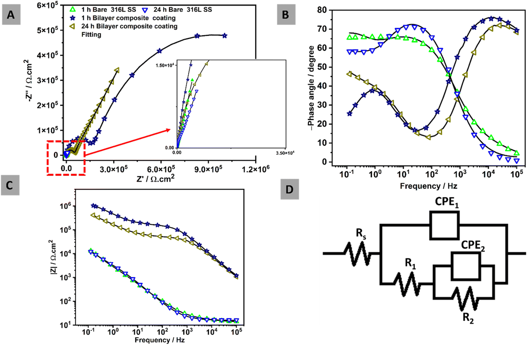 | ||
| Fig. 15 EIS spectra over immersion time in PBS at 37 ± 1 °C: (A) Nyquist plots, (B) Bode phase angles, (C) Bode impedances, and (D) equivalent electric circuit. | ||
Nyquist plots of all samples analyzed after 1 h and 24 h in PBS, as shown in Fig. 15A. The semi-capacitive arcs in the Nyquist plot of bare 316L SS remained unchanged over the immersion time, indicating that no corrosion was observed. In contrast, the bilayer composite coating over immersion time depicted a higher semi-capacitive arc,40 indicating higher corrosion resistance. Fig. 15B shows that the Bode phase plots with two-time constants are observed in all samples.
For the 316L SS substrate, the humps observed at the lowest frequencies (around 1 Hz) in the Bode-phase diagram (Fig. 15B) after 1 and 24 h are attributed to an inner compact layer of passive film early formed on the steel substrate, which acts as a strong diffusion barrier. However, the humps at higher frequencies are related to the outer layer of the oxide passive film on the 316L SS. The bilayer composite coating demonstrated a high-frequency hump at ∼10 kHz (at both 1 and 24 h immersion) due to the strong physical barrier property of the bilayer composite coating. The low-frequency response at around 1 Hz is again attributed to the inner layer of the passive film early formed on the steel substrate.
Fig. 15C presents the Bode impedance plots, where the low-frequency impedance value at 10−1 Hz (|Z| 0.1 Hz) is a common indicator for observing the properties of the coating. All curves illustrated comparable results except for the bilayer composite coating, which implies that no corrosion was observed over the immersion time of 24 h in PBS. The bilayer composite coatings showed higher impedance values over the immersion times (1 and 24 h) compared to 316L SS. The main reason for this is associated with the strengthening effect of TiO2/Cu-MBGNs in the bilayer composite coating. The EIS measurements were fitted by an electric equivalent circuit in Fig. 15D to determine the electrochemical behavior of the samples. Fig. 15D shows two-time constants, which are used to study the response of bare 316L SS and bilayer composite coating. In the electrical equivalent circuit, Rs represents the solution resistance. Whereas, CPE1 and R1 represented the capacitance of the double layer and resistance of the outer surface of bilayer composite coating and oxide layer of 316L SS, respectively. CPE2 and R2 represent the capacitance and resistance of the inner layer of bilayer composite coating and inner passive oxide layer of 316L SS, respectively.
Generally, CPE is used instead of pure capacitance to define the non-ideal capacitive behavior of the element, which is mainly attributed to the uneven growth of the generated layer.109 Fit values were measured for each sample, and fitting showed a Chi-square value in the 10−4 range, which is an indication of very good fits. The equivalent capacitance values of different elements in Fig. 15D can be calculated using CPE values (CPE1, CPE2, n1, and n2) with their respective resistance according to eqn (11),81 where Q, R, and n represent the charge, resistance, and exponent of the constant phase element for porous and passive barrier coating, respectively:
| CPE = Q1/nR(1−n)/n | (11) |
Table 3 EIS fitting values for each element in the electrical equivalent circuit.
| Samples | Rs (Ω cm2) | CPE1 (μΩ−1 sn cm2) | n1 - | R1 (Ω cm2) | CPE2 (μΩ−1 sn cm2) | n2 - | R2 (Ω cm2) | χ2 fits |
|---|---|---|---|---|---|---|---|---|
| 1 h Bare SS | 1.32 | 68.7 | 0.7 | 5.52 × 10³ | 22.1 | 0.8 | 6.04 × 10³ | 2.53 × 10⁻⁴ |
| 24 h Bare SS | 1.62 | 49.6 | 0.8 | 8.81 × 10³ | 40.6 | 0.8 | 7.22 × 10³ | 4.05 × 10⁻⁴ |
| 1 h Bilayer composite coating | 1.74 | 0.06 | 0.7 | 1.56 × 10⁷ | 0.006 | 0.8 | 1.5 × 10⁵ | 2.62 × 10⁻⁴ |
| 24 h Bilayer composite coating | 1.17 | 0.007 | 0.8 | 4.56 × 10⁵ | 2.5 | 0.8 | 9.07 × 10⁴ | 2.73 × 10⁻⁴ |
The bilayer composite coating demonstrated an impedance value of ∼1.56 × 10⁷ Ω cm2 after 1 h and decreased to ∼4.56 × 10⁵ Ω cm2 after 24 h. However, the impedance value of the bilayer composite coating was greater than that of the bare 316 L SS (8.81 × 10³ Ω cm2) even after 24 h immersion in PBS. Furthermore, the impedance value of the bilayer composite coating decreased after 24 h of immersion in PBS, but it was significantly higher than the impedance values of the bare 316L SS. This indicates that the bilayer composite coating showed improved corrosion resistance owing to its higher impedance of ∼4.56 × 10⁵ Ω cm2 after 24 h compared to bare 316L SS in PBS, as shown in Table 3.
Overall, the bilayer composite coating developed in this study exhibited suitable physical, mechanical, and electrochemical properties. However, detailed in vitro bioactivity studies, antibacterial studies (quantitative), and in vitro cell culture studies using direct and indirect methods should be carried out to confirm the suitability of the developed coatings for further in vivo and eventually clinical applications. Nevertheless, the significant improvement in corrosion and wear resistance is attributed to this study and is a significant milestone for PEEK-based composite coatings for orthopaedic applications.
4. Conclusions
The present study investigated the synergistic effects of TiO2/Cu-MBGNs in the bilayer composite coating deposited on 316L SS via EPD. First, a layer of PEEK was deposited on 316L SS substrate, followed by sintering at 350 °C for 30 min. Then, a second layer of TiO2/Cu-MBGNs was deposited and sintered again. PEEK layer and bilayer composite coating were analyzed through SEM/EDS and FTIR analyses. Moreover, XRD results demonstrated that TiO2/Cu-MBGNs are found in bilayer composite coating. The bilayer composite coating exhibited excellent mechanical strength, as confirmed by the bend test. The bilayer composite coating showed potential antibacterial activity against S. aureus and E. coli. A tribological study confirmed that the bilayer composite coating bears a 10 N load under DMEM, which mimics the human body environment. The EIS results of the bilayer composite coating in PBS showed good corrosion resistance, which is attributed to the synergistic effect of TiO2 and Cu-MBGNs with an increase in the barrier properties compared to the PEEK coating and the 316L SS.Data availability
The data that support the findings of this study are available from the corresponding author, Prof. Muhammad Atiq Ur Rehman (E-mail: atique1.1@hotmail.com), upon request.Conflicts of interest
There are no conflicts to declare.Acknowledgements
This research has been funded by Scientific Research Deanship at University of Hail-Saudi Arabia through Project number RG-23 228.References
- K. Bordjih, J.-Y. Jouzeau, D. Mainard, E. Payan, J.-P. Delagoutte and P. Netter, Evaluation of the effect of three surface treatments on the biocompatibility of 316L stainless steel using human differentiated cells, Biomaterials, 1996, 17, 491–500, DOI:10.1016/0142-9612(96)82723-2.
- D. Gopi, V. Collins Arun Prakash and L. Kavitha, Evaluation of hydroxyapatite coatings on borate passivated 316L SS in Ringer’s solution, Mater. Sci. Eng., C, 2009, 29(3), 955–958, DOI:10.1016/j.msec.2008.08.020.
- M. Li, T. Yin, Y. Wang, F. Du, X. Zou, H. Gregersen and G. Wang, Study of biocompatibility of medical grade high nitrogen nickel-free austenitic stainless steel in vitro, Mater. Sci. Eng., C, 2014, 43, 641–648 CrossRef CAS.
- U. Maver, K. Xhanari, M. Žižek, L. Gradišnik, K. Repnik, U. Potočnik and M. Finšgar, Carboxymethyl cellulose/diclofenac bioactive coatings on AISI 316LVM for controlled drug delivery, and improved osteogenic potential, Carbohydr. Polym., 2020, 230, 115612 CrossRef CAS PubMed.
- I. Gurappa, Development of appropriate thickness ceramic coatings on 316 L stainless steel for biomedical applications, Surf. Coat. Technol., 2002, 161(1), 70–78, DOI:10.1016/S0257-8972(02)00380-8.
- R. I. M. Asri, W. S. W. Harun, M. Samykano, N. A. C. Lah, S. A. C. Ghani, F. Tarlochan and M. R. Raza, Corrosion and surface modification on biocompatible metals: A review, Mater. Sci. Eng., C, 2017, 77, 1261–1274, DOI:10.1016/j.msec.2017.04.102.
- N. Eliaz, Corrosion of metallic biomaterials: A review, Materials, 2019, 12, 407, DOI:10.3390/ma12030407.
- T. M. Sridhar, U. K. Mudali and M. Subbaiyan, Preparation and characterisation of electrophoretically deposited hydroxyapatite coatings on type 316L stainless steel, Corros. Sci., 2003, 45, 237–252 CrossRef.
- G. Manivasagam, D. Dhinvdasekaran and A. Rajamanickam, Biomedical implants: corrosion and its prevention-a review, Recent Pat. Corros. Sci., 2010, 2, 40–54 CrossRef CAS.
- J. Alvarado, R. Maldonado, J. Marxuach and R. Otero, Biomechanics of hip and knee prostheses, Appl. Eng. Mech. Med. GED–University Puerto Rico Mayaguez, 2003, 1–20 Search PubMed.
- J. J. Ramsden, D. M. Allen, D. J. Stephenson, J. R. Alcock, G. N. Peggs, G. Fuller and G. Goch, The design and manufacture of biomedical surfaces, CIRP Ann., 2007, 56, 687–711 CrossRef.
- M. A. Hussein, A. S. Mohammed and N. Al-Aqeeli, Wear characteristics of metallic biomaterials: a review, Materials, 2015, 8, 2749–2768 CrossRef CAS.
- F. Ordikhani and A. Simchi, Long-term antibiotic delivery by chitosan-based composite coatings with bone regenerative potential, Appl. Surf. Sci., 2014, 317, 56–66, DOI:10.1016/j.apsusc.2014.07.197.
- F. Pishbin, A. Simchi, M. P. P. Ryan and A. R. R. Boccaccini, Electrophoretic deposition of chitosan/45S5 Bioglass composite coatings for orthopaedic applications, Surf. Coat. Technol., 2011, 205, 5260–5268, DOI:10.1016/j.surfcoat.2011.05.026.
- A. Bekmurzayeva, W. J. Duncanson, H. S. Azevedo and D. Kanayeva, Surface modification of stainless steel for biomedical applications: Revisiting a century-old material, Mater. Sci. Eng., C, 2018, 93, 1073–1089 CrossRef CAS.
- N. Sultana, Y. Nishina and M. Z. I. Nizami, Surface modifications of medical grade stainless steel, Coatings, 2024, 14, 248 CrossRef CAS.
- B. Mojarad Shafiee, R. Torkaman, M. Mahmoudi, R. Emadi, M. Derakhshan, E. Karamian and F. Tavangarian, Surface modification of 316L SS implants by applying bioglass/gelatin/polycaprolactone composite coatings for biomedical applications, Coatings, 2020, 10, 1220 CrossRef.
- L. Besra and M. Liu, A review on fundamentals and applications of electrophoretic deposition (EPD), Prog. Mater. Sci., 2007, 52, 1–61, DOI:10.1016/j.pmatsci.2006.07.001.
- S. N. Heavens, Electrophoretic deposition as a processing route for ceramics, Noyes Publ. Adv. Ceram. Process. Technol., 1990, 1, 255–283 CAS.
- A. R. Boccaccini, S. Keim, R. Ma, Y. Li and I. Zhitomirsky, Electrophoretic deposition of biomaterials, J. R. Soc. Interface, 2010, 7(Suppl 5), S581–S613, DOI:10.1098/rsif.2010.0156.focus.
- R. G. Raicheff and H. Z. Zahariev, Electrophoretic Deposition., 1982, 33–39, DOI:10.1016/b0-08-043152-6/00487-3.
- S. M. Kurtz, Chapter 1 - An Overview of PEEK Biomaterials, in Plast. Des. Libr., ed. S. M. B. T.-P. B. H. Kurtz, William Andrew Publishing, Oxford, 2012, pp. 1–7, DOI:10.1016/B978-1-4377-4463-7.10001-6.
- I. V. Panayotov, V. Orti, F. Cuisinier and J. Yachouh, Polyetheretherketone (PEEK) for medical applications, J. Mater. Sci.:Mater. Med., 2016, 27, 118, DOI:10.1007/s10856-016-5731-4.
- G. Skirbutis, A. Dzingutė, V. Masiliūnaitė, G. Šulcaitė and J. Žilinskas, A review of PEEK polymer's properties and its use in prosthodontics, Stomatologija, 2017, 19, 19–23 Search PubMed.
- K. Zheng, B. Sui, K. Ilyas and A. R. Boccaccini, Porous bioactive glass micro- and nanospheres with controlled morphology: developments, properties and emerging biomedical applications, Mater. Horiz., 2021, 8, 300–335, 10.1039/d0mh01498b.
- K. Zheng, J. Kang, B. Rutkowski, M. Gawęda, J. Zhang, Y. Wang, N. Founier, M. Sitarz, N. Taccardi and A. R. Boccaccini, Toward highly dispersed mesoporous bioactive glass nanoparticles with high cu concentration using cu/ascorbic acid complex as precursor, Front. Chem., 2019, 7, 1–15, DOI:10.3389/fchem.2019.00497.
- A. Bari, N. Bloise, S. Fiorilli, G. Novajra, M. Vallet-Regí, G. Bruni, A. Torres-Pardo, J. M. González-Calbet, L. Visai and C. Vitale-Brovarone, Copper-containing mesoporous bioactive glass nanoparticles as multifunctional agent for bone regeneration, Acta Biomater., 2017, 55, 493–504, DOI:10.1016/j.actbio.2017.04.012.
- Q. Nawaz, S. Fastner, M. A. U. Rehman, S. Ferraris, S. Perero, G. G. di Confiengo, E. Yavuz, M. Ferraris and A. R. Boccaccini, Multifunctional stratified composite coatings by electrophoretic deposition and RF co-sputtering for orthopaedic implants, J. Mater. Sci., 2021, 56, 7920–7935, DOI:10.1007/s10853-020-05725-w.
- M. A. Ur Rehman, S. Ferraris, W. H. Goldmann, S. Perero, F. E. Bastan, Q. Nawaz, G. D. G. Di Confiengo, M. Ferraris and A. R. Boccaccini, Antibacterial and Bioactive Coatings Based on Radio Frequency Co-Sputtering of Silver Nanocluster-Silica Coatings on PEEK/Bioactive Glass Layers Obtained by Electrophoretic Deposition, ACS Appl. Mater. Interfaces, 2017, 9, 32489–32497, DOI:10.1021/acsami.7b08646.
- M. A. Ur Rehman, F. E. Bastan, Q. Nawaz, W. H. Goldmann, M. Maqbool, S. Virtanen and A. R. Boccaccini, Electrophoretic deposition of lawsone loaded bioactive glass (BG)/chitosan composite on polyetheretherketone (PEEK)/BG layers as antibacterial and bioactive coating, J. Biomed. Mater. Res., Part A, 2018, 106, 3111–3122, DOI:10.1002/jbm.a.36506.
- A. Nawaz, S. S. S. Bano, M. Yasir, A. Wadood, M. A. Ur Rehman and M. A. U. Rehman, Ag and Mn-doped mesoporous bioactive glass nanoparticles incorporated into the chitosan/gelatin coatings deposited on PEEK/bioactive glass layers for favorable osteogenic differentiation and antibacterial activity, Mater. Adv., 2020, 1, 1273–1284, 10.1039/D0MA00325E.
- R. S. Virk, M. A. U. Rehman, M. A. Munawar, D. W. Schubert, W. H. Goldmann, J. Dusza and A. R. Boccaccini, Curcumin-Containing Orthopedic Implant Coatings Deposited on Poly-Ether-Ether-Ketone/Bioactive Glass/Hexagonal Boron Nitride Layers by Electrophoretic Deposition, Coatings, 2019, 9, 572, DOI:10.3390/coatings9090572.
- S. A. Batool, A. Wadood, S. W. Hussain, M. Yasir and M. A. Ur Rehman, A Brief Insight to the Electrophoretic Deposition of PEEK-, Chitosan-, Gelatin-, and Zein-Based Composite Coatings for Biomedical Applications: Recent Developments and Challenges, Surfaces, 2021, 4, 205–239, DOI:10.3390/surfaces4030018.
- M. A. U. Rehman and S. A. Batool, Development of sustainable antibacterial coatings based on electrophoretic deposition of multilayers: gentamicin-loaded chitosan/gelatin/bioactive glass deposition on PEEK/bioactive glass layer, Int. J. Adv. Manuf. Technol., 2022, 120, 3885–3900, DOI:10.1007/s00170-022-09024-3.
- M. Atiq, U. Rehman, F. E. Bastan, Q. Nawaz, W. H. Goldmann, M. Maqbool, S. Virtanen and A. R. Boccaccini, Electrophoretic deposition of lawsone loaded bioactive glass (BG)/chitosan composite on polyetheretherketone (PEEK)/BG layers as antibacterial and bioactive coating, J. Biomed. Mater. Res., Part A, 2018, 1–12, DOI:10.1002/jbm.a.36506.
- M. A. Ur Rehman, F. E. Bastan, A. Nawaz, Q. Nawaz, A. Wadood, M. A. U. Rehman, F. E. Bastan, A. Nawaz, Q. Nawaz and A. Wadood, Electrophoretic deposition of PEEK/bioactive glass composite coatings on stainless steel for orthopedic applications: an optimization for in vitro bioactivity and adhesion strength, Int. J. Adv. Manuf. Technol., 2020, 108, 1849–1862, DOI:10.1007/s00170-020-05456-x.
- S. Kumari, Shweta, R. K. Mishra, Z. Fatima, S. K. Avinashi, S. Parveen, S. Kumar, A. Shamsad, P. Behera and J. Rao, Optimized Performance of PMMA Denture Base Material: Enhanced Mechanical, Biocompatibility, and Antibacterial Properties Modified with Extracted Jackfruit Latex Resin (Artocarpus Heterophyllus), J. Inorg. Organomet. Polym. Mater., 2024, 1–17 Search PubMed.
- S. Kumari, A. Hussain, J. Rao, K. Singh, S. K. Avinashi and C. Gautam, Structural, mechanical and biological properties of PMMA-ZrO2 nanocomposites for denture applications, Mater. Chem. Phys., 2023, 295, 127089 CrossRef CAS.
- S. Kumari, R. K. Mishra, S. Parveen, S. K. Avinashi, A. Hussain, S. Kumar, M. Banerjee, J. Rao, R. Kumar and R. K. Gautam, Fabrication, structural, and enhanced mechanical behavior of MgO substituted PMMA composites for dental applications, Sci. Rep., 2024, 14, 2128 CrossRef CAS.
- K. Ahmad, S. A. Batool, M. T. Farooq, B. Minhas, J. Manzur, M. Yasir, A. Wadood, E. Avcu and M. A. Ur Rehman, Corrosion, surface, and tribological behavior of electrophoretically deposited polyether ether ketone coatings on 316L stainless steel for orthopedic applications, J. Mech. Behav. Biomed. Mater., 2023, 148, 106188, DOI:10.1016/j.jmbbm.2023.106188.
- C. Morsiya, A review on parameters affecting properties of biomaterial SS 316L, Aust. J. Mech. Eng., 2022, 20, 803–813, DOI:10.1080/14484846.2020.1752975.
- D. A. Keane, J. P. Hanrahan, M. P. Copley, J. D. Holmes and M. A. Morris, A modified Stöber process for the production of mesoporous Sub 2 micron silica microspheres; applications in HPLC, J. Porous Mater., 2010, 17, 145–152, DOI:10.1007/s10934-009-9274-7.
- F. Westhauser, S. Decker, Q. Nawaz, F. Rehder, S. Wilkesmann, A. Moghaddam, E. Kunisch and A. R. Boccaccini, Impact of zinc-or copper-doped mesoporous bioactive glass nanoparticles on the osteogenic differentiation and matrix formation of mesenchymal stromal cells, Materials, 2021, 14(8), 1864, DOI:10.3390/ma14081864.
- C. Wang, J. Ma and W. Cheng, Formation of polyetheretherketone polymer coating by electrophoretic deposition method, Surf. Coat. Technol., 2003, 173, 271–275, DOI:10.1016/S0257-8972(03)00626-1.
- A. R. Boccaccini, C. Peters, J. A. Roether, D. Eifler, S. K. Misra and E. J. Minay, Electrophoretic deposition of polyetheretherketone (PEEK) and PEEK/Bioglass® coatings on NiTi shape memory alloy wires, J. Mater. Sci., 2006, 41, 8152–8159, DOI:10.1007/s10853-006-0556-z.
- E. Avcu, F. E. Baştan, H. Z. Abdullah, M. A. U. Rehman, Y. Y. Avcu and A. R. Boccaccini, Electrophoretic deposition of chitosan-based composite coatings for biomedical applications: A review, Prog. Mater. Sci., 2019, 103, 69–108, DOI:10.1016/j.pmatsci.2019.01.001.
- I. Corni, N. Neumann, S. Novak, K. König, P. Veronesi, Q. Chen, M. P. Ryan and A. R. Boccaccini, Electrophoretic deposition of PEEK-nano alumina composite coatings on stainless steel, Surf. Coat. Technol., 2009, 203, 1349–1359, DOI:10.1016/j.surfcoat.2008.11.005.
- S. Seuss, T. Subhani, M. Y. Kang, K. Okudaira, I. E. Aguilar Ventura and A. R. Boccaccini, Electrophoretic Deposition of PEEK-TiO2 Composite Coatings on Stainless Steel, Key Eng. Mater., 2012, 507, 127–133, DOI:10.4028/www.scientific.net/KEM.507.127.
- S. Seuss, M. Heinloth and A. R. Boccaccini, Development of bioactive composite coatings based on combination of PEEK, bioactive glass and Ag nanoparticles with antibacterial properties, Surf. Coat. Technol., 2016, 301, 100–105, DOI:10.1016/j.surfcoat.2016.03.057.
- K. Ahmad, J. Manzur, M. Tahir, R. Hussain, M. Khan, A. Wadood, E. Avcu and M. A. U. Rehman, Electrophoretic deposition, microstructure and selected properties of zein/cloves coatings on 316L stainless steel, Prog. Org. Coat., 2023, 176, 107407, DOI:10.1016/j.porgcoat.2023.107407.
- M. Li, P. Xiong, M. Mo, Y. Cheng and Y. Zheng, Electrophoretic-deposited novel ternary silk fibroin/graphene oxide/hydroxyapatite nanocomposite coatings on titanium substrate for orthopedic applications, Front. Mater. Sci., 2016, 10, 270–280, DOI:10.1007/s11706-016-0347-7.
- F. E. Baştan, M. Atiq Ur Rehman, Y. Y. Avcu, E. Avcu, F. Üstel and A. R. Boccaccini, Electrophoretic co-deposition of PEEK-hydroxyapatite composite coatings for biomedical applications, Colloids Surf., B, 2018, 169, 176–182, DOI:10.1016/j.colsurfb.2018.05.005.
- W.-W. Li, H.-Y. Wang and Y.-Q. Zhang, A novel chitosan hydrogel membrane by an improved electrophoretic deposition and its characteristics in vitro and in vivo, Mater. Sci. Eng., C, 2017, 74, 287–297 CrossRef CAS.
- N. S. Raddaha, L. Cordero-Arias, S. Cabanas-Polo, S. Virtanen, J. A. Roether and A. R. Boccaccini, Electrophoretic deposition of chitosan/h-BN and chitosan/h-BN/TiO2 composite coatings on stainless steel (316L) substrates, Materials, 2014, 7, 1814–1829, DOI:10.3390/ma7031814.
- A. Zhitomirsky and I. Hashambhoy, Chitosan-mediated Electrosynthesis of Organic–inorganic Nanocomposites, J. Mater. Process. Technol., 2007, 191, 68–72 CrossRef.
- I. Zhitomirsky, Cathodic electrodeposition of ceramic and organoceramic materials. Fundamental aspects, Adv. Colloid Interface Sci., 2002, 97, 279–317 CrossRef CAS.
- F. Pishbin, A. Simchi, M. P. Ryan and A. R. Boccaccini, Electrophoretic deposition of chitosan/45S5 Bioglass® composite coatings for orthopaedic applications, Surf. Coat. Technol., 2011, 205, 5260–5268, DOI:10.1016/j.surfcoat.2011.05.026.
- S. Mahmoodi, L. Sorkhi, M. Farrokhi-Rad and T. Shahrabi, Electrophoretic deposition of hydroxyapatite–chitosan nanocomposite coatings in different alcohols, Surf. Coat. Technol., 2013, 216, 106–114, DOI:10.1016/j.surfcoat.2012.11.032.
- S. Clavijo, F. Membrives, G. Quiroga, A. R. Boccaccini and M. J. Santillán, Electrophoretic deposition of chitosan/Bioglass® and chitosan/Bioglass®/TiO2 composite coatings for bioimplants, Ceram. Int., 2016, 42, 14206–14213, DOI:10.1016/j.ceramint.2016.05.178.
- J. Zhang, Z. Wen, M. Zhao, G. Li and C. Dai, Effect of the addition CNTs on performance of CaP/chitosan/coating deposited on magnesium alloy by electrophoretic deposition, Mater. Sci. Eng., C, 2016, 58, 992–1000 CrossRef CAS PubMed.
- M. Atiq Ur Rehman, F. E. Bastan, B. Haider, A. R. Boccaccini, M. A. U. Rehman, F. E. Bastan, B. Haider and A. R. Boccaccini, Electrophoretic deposition of PEEK/bioactive glass composite coatings for orthopedic implants: A design of experiments (DoE) study, Mater. Des., 2017, 130, 223–230, DOI:10.1016/j.matdes.2017.05.045.
- P. N. De Aza, A. H. De Aza, P. Pena and S. De Aza, Bioactive glasses and glass-ceramics, Boletin-Sociedad Esp, Ceram. Vidrio, 2007, 46, 45 CrossRef CAS.
- H. E. Bergna, Colloid chemistry of silica: An overview, Surfactant Sci. Ser., 2006, 131, 9–35 CAS.
- I. Corni, M. P. Ryan and A. R. Boccaccini, Electrophoretic deposition: From traditional ceramics to nanotechnology, J. Eur. Ceram. Soc., 2008, 28, 1353–1367 CrossRef CAS.
- I. Corni, N. Neumann, D. Eifler and A. R. Boccaccini, Polyetheretherketone (PEEK) Coatings on Stainless Steel by Electrophoretic Deposition, Adv. Eng. Mater., 2008, 10, 559–564, DOI:10.1002/adem.200800010.
- M. A. U. Rehman, F. E. Bastan, B. Haider and A. R. Boccaccini, Electrophoretic deposition of PEEK/bioactive glass composite coatings for orthopedic implants: A design of experiments (DoE) study, Mater. Des., 2017, 130, 223–230 CrossRef.
- F. Pishbin, A. Simchi, M. P. Ryan and A. R. Boccaccini, A study of the electrophoretic deposition of Bioglass® suspensions using the Taguchi experimental design approach, J. Eur. Ceram. Soc., 2010, 30, 2963–2970 CrossRef CAS.
- R. S. Virk, M. A. Ur Rehman and A. R. Boccaccini, PEEK Based Biocompatible Coatings Incorporating h-BN and Bioactive Glass by Electrophoretic Deposition, ECS Trans., 2018, 82, 89–95, DOI:10.1149/08201.0089ecst.
- M. D. De, W. De Lima and H. Nunes, Biocompatible Sulphonated PEEK Spheres : Influence of Processing Conditions on Morphology and Swelling Behavior, Polymers, 2021,(13), 2920, DOI:10.3390/polym13172920.
- S. Bano, M. Akhtar, M. Yasir, M. S. Maqbool, A. Niaz, A. Wadood, M. Atiq and U. Rehman, Synthesis and Characterization of Silver–Strontium (Ag-Sr)-Doped Mesoporous Bioactive Glass Nanoparticles, Gels, 2021, 7, 1–15, DOI:10.3390/gels7020034.
- M. Mozafari, F. Moztarzadeh and M. Tahriri, Investigation of the physico-chemical reactivity of a mesoporous bioactive SiO2-CaO-P2O5 glass in simulated body fluid, J. Non-Cryst. Solids, 2010, 356, 1470–1478, DOI:10.1016/j.jnoncrysol.2010.04.040.
- G. Nagaraj, D. Brundha, C. Chandraleka, M. Arulpriya, V. Kowsalya, S. Sangavi, R. Jayalakshmi, S. Tamilarasu and R. Murugan, Facile synthesis of improved anatase TiO2 nanoparticles for enhanced solar-light driven photocatalyst, SN Appl. Sci., 2020, 2, 734, DOI:10.1007/s42452-020-2554-1.
- A. Kurdi, H. Wang and L. Chang, Effect of nano-sized TiO2 addition on tribological behaviour of poly ether ether ketone composite, Tribol. Int., 2018, 117, 225–235, DOI:10.1016/j.triboint.2017.09.002.
- Y. Niu, S. Zheng, P. Song, X. Zhang and C. Wang, Mechanical and thermal properties of PEEK composites by incorporating inorganic particles modified phosphates, Composites, Part B, 2021, 212, 108715, DOI:10.1016/j.compositesb.2021.108715.
- J. C. Sébileau, S. Lemonnier, E. Barraud, M. F. Vallat, A. Carradò and M. Nardin, Effects of pressure on poly(ether-ether-ketone) (PEEK) sintering mechanisms, J. Appl. Polym. Sci., 2019, 136, 1–9, DOI:10.1002/app.47645.
- Z. Tabia, K. El Mabrouk, M. Bricha and K. Nouneh, Mesoporous bioactive glass nanoparticles doped with magnesium: Drug delivery and acellular: In vitro bioactivity, RSC Adv., 2019, 9, 12232–12246, 10.1039/c9ra01133a.
- N. E. Iram, M. S. Khan, R. Jolly, M. Arshad, M. Alam, P. Alam, R. H. Khan and F. Firdaus, Interaction mode of polycarbazole-titanium dioxide nanocomposite with DNA: Molecular docking simulation and in-vitro antimicrobial study, J. Photochem. Photobiol., B, 2015, 153, 20–32, DOI:10.1016/j.jphotobiol.2015.09.001.
- M. A. U. Rehman, F. E. Bastan, Q. Nawaz, A. R. Boccaccini, M. Atiq, U. Rehman, F. E. Bastan, Q. Nawaz, A. R. Boccaccini, M. A. U. Rehman, F. E. Bastan, Q. Nawaz, A. R. Boccaccini, M. Atiq, U. Rehman, F. E. Bastan, Q. Nawaz and A. R. Boccaccini, Electrophoretic deposition of lawsone loaded nanoscale silicate glass/chitosan composite on PEEK/BG layers, Electrochem. Soc. Tras, 2018, 82, 45–50, DOI:10.1149/08201.0045ecst.
- F. Baino, Copper-Doped Ordered Mesoporous Bioactive Glass: A Promising Multifunctional Platform for Bone Tissue Engineering, Bioengineering, 2020, 7, 45, DOI:10.3390/bioengineering7020045.
- D. Marovic, H. J. Haugen, V. Negovetic Mandic, M. Par, K. Zheng, Z. Tarle and A. R. Boccaccini, Incorporation of Copper-Doped Mesoporous Bioactive Glass Nanospheres in Experimental Dental Composites: Chemical and Mechanical Characterization, Materials, 2021, 14, 2611, DOI:10.3390/ma14102611.
- B. Minhas, S. Dino, H. Qian and Y. Zuo, An approach for high stability TiO2 in strong acid environments at high temperature, Surf. Coat. Technol., 2020, 395, 125932, DOI:10.1016/j.surfcoat.2020.125932.
- S. Saravanan, M. Balamurugan and T. Soga, Synthesis of titanium dioxide nanoparticles with desired ratio of anatase and rutile phases and the effect of high temperature annealing, Trans. Mater. Res. Soc. Jpn., 2018, 43, 255–261 CrossRef CAS.
- J. Song, Z. Liao, H. Shi, D. Xiang, Y. Liu, W. Liu and Z. Peng, Fretting Wear Study of PEEK-Based Composites for Bio-implant Application, Tribol. Lett., 2017, 65, 150, DOI:10.1007/s11249-017-0931-8.
- M. Mielczarek, J. Marchewka, K. Kowalski, Ł. Cieniek, M. Sitarz and T. Moskalewicz, Effect of tea tree oil addition on the microstructure, structure and selected properties of chitosan-based coatings electrophoretically deposited on zirconium alloy substrates, Appl. Surf. Sci., 2023, 609, 155266, DOI:10.1016/j.apsusc.2022.155266.
- J. Ureña, S. Tsipas, A. Jiménez-Morales, E. Gordo, R. Detsch and A. R. Boccaccini, Cellular behaviour of bone marrow stromal cells on modified Ti-Nb surfaces, Mater. Des., 2018, 140, 452–459, DOI:10.1016/j.matdes.2017.12.006.
- F. Kuśmierczyk, Ł. Cieniek, A. Kopia, S. Zimowski and T. Moskalewicz, Development and Characterization of Multilayered Cu/HA/ZnS + PEEK Coating System by Hybrid Technology, Metall. Mater. Trans. A Phys. Metall. Mater. Sci., 2023, 54, 2803–2818, DOI:10.1007/s11661-023-07057-1.
- K. L. Menzies and L. Jones, The impact of contact angle on the biocompatibility of biomaterials, Optom. Vis. Sci., 2010, 87, 387–399, DOI:10.1097/OPX.0b013e3181da863e.
- J. I. Rosales-Leal, M. A. Rodríguez-Valverde, G. Mazzaglia, P. J. Ramón-Torregrosa, L. Díaz-Rodríguez, O. García-Martínez, M. Vallecillo-Capilla, C. Ruiz and M. A. Cabrerizo-Vílchez, Effect of roughness, wettability and morphology of engineered titanium surfaces on osteoblast-like cell adhesion, Colloids Surf., A, 2010, 365, 222–229 CrossRef CAS.
- F. Rupp, L. Scheideler, D. Rehbein, D. Axmann and J. Geis-Gerstorfer, Roughness induced dynamic changes of wettability of acid etched titanium implant modifications, Biomaterials, 2004, 25, 1429–1438 CrossRef CAS PubMed.
- F. Gebhardt, S. Seuss, M. C. Turhan, H. Hornberger, S. Virtanen and A. R. Boccaccini, Characterization of electrophoretic chitosan coatings on stainless steel, Mater. Lett., 2012, 66, 302–304 CrossRef CAS.
- C. N. Elias, Y. Oshida, J. H. C. Lima and C. A. Muller, Relationship between surface properties (roughness, wettability and morphology) of titanium and dental implant removal torque, J. Mech. Behav. Biomed. Mater., 2008, 1, 234–242 CrossRef PubMed.
- L. Cordero-Arias, S. Cabanas-Polo, H. Gao, J. Gilabert, E. Sanchez, J. A. Roether, D. W. Schubert, S. Virtanen and A. R. Boccaccini, Electrophoretic deposition of nanostructured-TiO2/chitosan composite coatings on stainless steel, RSC Adv., 2013, 3, 11247–11254, 10.1039/c3ra40535d.
- L. Mino, Á. Morales-García, S. T. Bromley and F. Illas, Understanding the nature and location of hydroxyl groups on hydrated titania nanoparticles, Nanoscale, 2021, 13, 6577–6585 RSC.
- J. N. Oliver, Y. Su, X. Lu, P.-H. Kuo, J. Du and D. Zhu, Bioactive glass coatings on metallic implants for biomedical applications, Bioact. Mater., 2019, 4, 261–270, DOI:10.1016/j.bioactmat.2019.09.002.
- F. E. Baştan, Fabrication and characterization of an electrostatically bonded PEEK-hydroxyapatite composites for biomedical applications, J. Biomed. Mater. Res., Part B, 2020, 108, 2513–2527 CrossRef.
- S. Priyadarshini, S. Sulava, R. Bhol and S. Jena, Green synthesis of silver nanoparticles using Azadirachta indica and Ocimum sanctum leaf extract, Curr. Sci., 2019, 117, 1300–1307 CrossRef CAS.
- M. Salah, N. A. S. Elkabbany and A. M. Partila, Evaluation of the cytotoxicity and antibacterial activity of nano-selenium prepared via gamma irradiation against cancer cell lines and bacterial species, Sci. Rep., 2024, 14, 20523, DOI:10.1038/s41598-024-69730-8.
- M. H. Abdulkareem, A. H. Abdalsalam and A. J. Bohan, Influence of chitosan on the antibacterial activity of composite coating (PEEK/HAp) fabricated by electrophoretic deposition, Prog. Org. Coat., 2019, 130, 251–259 CrossRef CAS.
- W. Zhang, G. Wang, Y. Liu, X. Zhao, D. Zou, C. Zhu, Y. Jin, Q. Huang, J. Sun, X. Liu, X. Jiang and H. Zreiqat, The synergistic effect of hierarchical micro/nano-topography and bioactive ions for enhanced osseointegration, Biomaterials, 2013, 34, 3184–3195, DOI:10.1016/j.biomaterials.2013.01.008.
- Z. Lin, Y. Cao, J. Zou, F. Zhu, Y. Gao, X. Zheng, H. Wang, T. Zhang and T. Wu, Improved osteogenesis and angiogenesis of a novel copper ions doped calcium phosphate cement, Mater. Sci. Eng., C, 2020, 114, 111032, DOI:10.1016/j.msec.2020.111032.
- R. A. Castillo-Rodríguez, G. Palencia, I. Anaya-Rubio, J. C. G. Pérez, D. Jiménez-Farfán, Á. Escamilla-Ramírez, S. Zavala-Vega, A. Cruz-Salgado, C. Cervantes-Rebolledo, I. Gracia-Mora, L. Ruiz-Azuara and C. Trejo-Solis, Anti-proliferative, pro-apoptotic and anti-invasive effect of the copper coordination compound Cas III-La through the induction of reactive oxygen species and regulation of Wnt/β-catenin pathway in glioma, J. Cancer, 2021, 12, 5693–5711, DOI:10.7150/jca.59769.
- S. Ehyai, M. G. Dionyssiou, J. W. Gordon, D. Williams, K. W. M. Siu and J. C. McDermott, A p38 Mitogen-Activated Protein Kinase-Regulated Myocyte Enhancer Factor 2–β-Catenin Interaction Enhances Canonical Wnt Signaling, Mol. Cell. Biol., 2016, 36, 330–346, DOI:10.1128/MCB.00832-15.
- R. A. Dodds, I. E. James, D. Rieman, R. Ahern, S. M. Hwang, J. R. Connor, S. D. Thompson, D. F. Veber, F. H. Drake, S. Holmes, M. W. Lark and M. Gowen, Human Osteoclast Cathepsin K Is Processed Intracellularly Prior to Attachment and Bone Resorption, J. Bone Miner. Res., 2001, 16, 478–486, DOI:10.1359/jbmr.2001.16.3.478.
- M. E. Caetano-Silva, L. A. Rund, M. Vailati-Riboni, M. T. B. Pacheco and R. W. Johnson, Copper-Binding Peptides Attenuate Microglia Inflammation through Suppression of NF-kB Pathway, Mol. Nutr. Food Res., 2021, 65, 2100153, DOI:10.1002/mnfr.202100153.
- Y. Wang, L. Shi, D. Duan, S. Li and J. Xu, Tribological properties of Zr61Ti2Cu25Al12 bulk metallic glass under simulated physiological conditions, Mater. Sci. Eng., C, 2014, 37, 292–304, DOI:10.1016/j.msec.2014.01.016.
- C. Liao, Y. Li and S. C. Tjong, Polyetheretherketone and Its Composites for Bone Replacement and Regeneration, Polymers, 2020, 12, 2858, DOI:10.3390/polym12122858.
- A. S. Mohammed and M. Irfan Fareed, Surface Modification of Polyether Ether Ketone (PEEK) with a Thin Coating of UHMWPE for Better Tribological Properties, Tribol. Trans., 2017, 60, 881–887, DOI:10.1080/10402004.2016.1225876.
- M. A. Ur Rehman, S. Ferraris, W. H. Goldmann, S. Perero, F. E. Bastan, Q. Nawaz, G. G. Di Confiengo, M. Ferraris and A. R. Boccaccini, Antibacterial and Bioactive Coatings Based on Radio Frequency Co-Sputtering of Silver Nanocluster-Silica Coatings on PEEK/Bioactive Glass Layers Obtained by Electrophoretic Deposition, ACS Appl. Mater. Interfaces, 2017, 9, 32489–32497, DOI:10.1021/acsami.7b08646.
- B. Minhas, S. Dino, L. Huang and D. Wu, Active Corrosion Protection by Epoxy Coating on Li2CO3-Pretreated Anodized Aluminum Alloy 2024-T3, Front. Mater., 2022, 8, 804328, DOI:10.3389/fmats.2021.804328.
| This journal is © The Royal Society of Chemistry 2025 |