Technoeconomic analysis of fine chemical electrosynthesis: a case study using electrooxidation of 2-methylnaphthelene to vitamin K3†
Qifeng
Yang
ab,
Liping
Liang
c,
Ning
Xu
ab,
Yang
Li
ab,
Zhihui
Wang
c,
Dadong
Shen
c and
Yiming
Mo
 *ab
*ab
aCollege of Chemical and Biological Engineering, Zhejiang University, Hangzhou 310027, China. E-mail: yimingmo@zju.edu.cn
bHangzhou Global Scientific and Technological Innovation Center, Zhejiang University, Hangzhou 311215, China
cZhejiang Medicine Co., Ltd, Shaoxing 310050, China
First published on 8th October 2024
Abstract
Electroorganic synthesis has received significant attention due to its environmentally friendly nature, offering the potential to replace traditional hazardous chemical production routes. However, an in-depth technoeconomic analysis (TEA) of electrosynthesis technology is still necessary to objectively assess the economic viability of this technology as an alternative to the traditional chemical syntheses. In this study, we used the cerium-mediated electrosynthesis of 2-methyl-1,4-naphthoquinone (2-MNQ, also known as vitamin K3) as a case study. The process development was conducted in both small-scale and large-scale electrochemical flow cells with 6.25 cm2 and 208 cm2 electrode sizes, respectively, to investigate the process scalability. Under the optimal conditions, a 66% yield was achieved for 2-MNQ with 90% faradaic efficiency at 50 mA cm−2 current density. We performed a comprehensive TEA on the key factors influencing electroorganic synthesis, including current density, electrode cost and lifespan, membranes, and electricity price. Furthermore, considering ongoing technological advancements in electrodes, membranes, and renewable electricity generation, we analyzed the trend of future projected cost reductions for electrosynthesis processes.
1. Introduction
Traditional organic redox reactions typically require stoichiometric amounts of hazardous oxidants or reductants, thus generating substantial by-product waste. This poses significant environmental and safety issues, motivating the development of sustainable synthetic technologies as alternatives to existing methods. Recently, the surging attention towards electrochemical synthesis has provided a versatile and environmentally friendly methodology using cost-effective electricity under mild conditions with high atom efficiency.1–9 These advantages stem from the use of electrons as redox agents and adjustable redox potential, thereby avoiding harsh operating conditions and terminal oxidants or reductants.10–12 Benefiting from these advantages, electroorganic synthesis has received increasing attention. Currently, several products, such as adiponitrile, tetraethyllead, butynediol, and hexachloroplatinic acid, are produced on the industrial scale using electrosynthesis methods.13–16Despite the sustainability benefits of electrosynthesis technology, its eventual industrial applications have to be driven by the overall economic benefits, such that traditional manufacturing processes could be substituted. The common first intuition of the electrosynthesis technology is that using cheaply available electricity to replace expensive redox reagents could significantly reduce the cost of the chemical production. This intuition is supported by a simple cost comparison, where the cost of one mole of electrons provided by electricity (assuming 5 V electrolysis voltage, 100% faradaic efficiency, and $0.1 per kW h electricity price) is $0.013 per mol, while providing equivalent electrons using redox reagents is significantly more expensive ($0.022 per mol for electrons from sodium hypochlorite and $0.096 per mol for electrons from zinc powder, see the ESI† for detailed calculations). However, the actual cost comparison is significantly more complicated than the intuitions above. Sargent and Jaramillo et al. conducted a thorough technoeconomic analysis (TEA) of electrochemical conversion of carbon dioxide (CO2) into valuable feedstock molecules.17 But for the electrosynthesis of high-value fine chemicals, there are few reports focusing on analyzing the practical aspects of a newly developed electrosynthesis method going towards large-scale applications.
The practical implementation of electrosynthesis technology requires a comprehensive consideration of various factors, such as electrode cost, electrode lifespan, electricity price, equipment investment, and safety.18–21 These factors may have inherent correlations. For instance, the electrode material, a key factor for determining electrode cost, is closely related to reaction selectivity, faradaic efficiency (FE), and electrolysis voltage. Therefore, a detailed assessment of these convoluted cost factors is necessary to obtain an objective understanding of the economic benefits of the electrosynthesis method as compared to traditional approaches. Furthermore, with the recent rapid development of renewable energy (e.g., solar and wind power), electricity cost is projected to gradually decrease in the near future, which directly impacts the electricity cost of the electrochemical process.22–24 Additionally, high-performance electrocatalysts or electrode materials are being continuously developed, which could significantly promote the efficiency of electrode reactions.25,26 Therefore, conducting an in-depth technoeconomic analysis of electrosynthesis taking the future technological advancement into consideration is an urgent task for adopting electrosynthesis in the practical fine chemical manufacturing.
In this study, we selected the development of the electrosynthesis process of 2-methyl-1,4-naphthoquinone (2-MNQ, also known as vitamin K3) as an example for TEA. 2-MNQ has important pharmacological activity and serves as a precursor for the synthesis of other vitamin K analogs.27,28 There exist various methods to synthesize 2-MNQ, among which the approach using 2-methylnaphthalene (2-MN) as the starting substrate illustrates the best economical potential (Table S2†).29–32 The existing industrial production route for 2-MNQ relies on chromic anhydride oxidation (Scheme 1). However, this synthesis route uses highly toxic chromium trioxide (CrO3) as the terminal oxidant, leading to generation of 18 kg carcinogenic chromium-containing wastewater for every kilogram of 2-MNQ synthesized.33–35 Thus, there is a strong motivation to develop greener alternatives to the existing CrO3 method, while still possessing the required economic competitiveness.
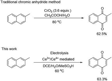 | ||
| Scheme 1 Traditional chromic anhydride method and electrochemical method for the synthesis of 2-MNQ. | ||
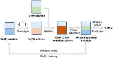
Herein, we utilized a chromium-free electrochemical method to achieve the selective conversion of 2-MN to 2-MNQ. This method is a cerium-mediated electrochemical–chemical cascade reaction, which first electrooxidizes aqueous Ce3+ into Ce4+ and then uses Ce4+ to oxidize 2-MN dissolved in the organic phase into 2-MNQ. After liquid–liquid phase separation, the spent Ce3+ aqueous solution can be recycled back to the electrooxidation step for the next round of 2-MN oxidation, thus, resulting in no metal ions released during the 2-MNQ electrosynthesis process. We systematically investigated the parameters for the cerium-mediated electrochemical–chemical cascade reaction for 2-MNQ synthesis. The electrooxidation of Ce3+ into Ce4+ was conducted in small- and large-scale flow cells to understand the scalability for an electrochemical process. Based on the optimized process parameters, we performed detailed TEA for the electrochemical 2-MNQ synthesis process and evaluated the contributing cost factors for an electrochemical process. Finally, considering the increasing availability of cheaper electricity and advancement of electrocatalysis technology, we analyzed the potential cost reduction of the electrochemical process, projecting the economic driving force to adopt electrosynthesis in the future.
2. Experimental methods
2.1 Chemicals and materials
2-MN, 1,10-phenanthroline and dichloroethane (DCE) were purchased from Aladdin Industrial Inc. Cerium carbonate hydrate (Ce2(CO3)3·xH2O), methanesulfonic acid (MeSO3H, 70 wt%), and 0.1 M standard solution of ammonium ferrous sulfate titrant (Fe(NH4)2·(SO4)2) were obtained from Macklin Industrial Inc. The amount of water in Ce2(CO3)3·xH2O was determined to be 8.5 (by calcining at 700 °C in an air for 5 hours, the cerium salt hydrate was completely converted to cerium dioxide, allowing for the determination of the water content). All chemical reagents and solvents utilized in this work were of analytical grade. A dimensionally stable anode (DSA) electrode and platinized titanium electrode were obtained from Shanximaize Technologies Co. Ltd. A Nafion 117 membrane was acquired from Electrochemical Factory.2.2 Electrochemical cerium oxidation
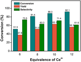
2.3 Procedure for cerium(IV) ion titration
A reported procedure was used for cerium(IV) ion titration.36,37 In brief, 2 mL of 0.1 M ammonium ferrous sulfate standard titrant solution was measured and 2 drops of 0.01 M o-phenanthroline aqueous solution were added as the color indicator. The ferrous sulfate solution was titrated with an electrolyzed cerium salt solution until the solution changed from red to colorless. The titration was repeated three times and the average value was taken as the cerium ion concentration.2.4 Procedure for cerium-mediated oxidation of 2-MN
For small-scale oxidation of 2-MN, to a 50 mL round-bottom flask, 2-MN (1 mmol, 142.2 mg) dissolved in 10 mL DCE was mixed with 25 mL of the prepared 0.4 M Ce4+ solution (containing 0.4 M Ce4+, 0.083 M Ce3+, 3.5 M H+, and 5.35 M MeSO3−). The 0.4 M Ce4+ solution was obtained by diluting a 0.6 M Ce4+ solution produced by electrolysis with 50% volume water. The mixture was allowed to react for 2 h at 60 °C under magnetic stirring at 1000 rotations per minute (RPM).For large-scale oxidation of 2-MN, to a 2000 mL jacketed reaction vessel, 2-MN (24 mmol, 3.412 g) dissolved in 240 mL of DCE was mixed with 600 mL of the prepared aqueous Ce4+ solution (0.4 M) (Fig. S1†). The mixture was allowed to react for 3 hours at 65 °C with vigorous mechanical stirring using a mechanical stirrer. The reaction temperature was controlled using a temperature control unit (DHJF-4005A).
After the reaction, mesitylene was added as an internal standard to the reaction mixture. The reaction solution was extracted three times consecutively using ethyl acetate. A portion of the extract was taken, the water was removed using anhydrous magnesium sulfate, and the conversion rate and products were analyzed using gas chromatography–mass spectrometry (GC–MS).
3. Results and discussion
3.1 Process development of the electrochemical 2-MNQ synthesis
We first sought to optimize the parameters for this cerium-mediated electrochemical–chemical cascade reaction using a small-scale flow cell (Table S1†). Compared with single-step electrocatalytic cerium-mediated 2-MNQ synthesis, the cerium-mediated electrochemical–chemical cascade reaction approach gave a better reaction selectivity (ESI† section S6). The best-performing reaction conditions found were as follows: (1) for electrooxidation of Ce3+, a flow cell with a DSA anode (6.25 cm2) and a platinum sheet cathode (6.25 cm2) was used to electrolyze Ce3+ to Ce4+ in the anolyte and to electrolyze H+ to H2 in the catholyte. The current density was 50 mA cm−2 and the amount of charge supplied was 87![[thin space (1/6-em)]](https://www.rsc.org/images/entities/char_2009.gif) 834 C per mole of Ce3+, giving 90% FE for Ce4+ generation and obtaining an anolyte solution containing 0.6 M Ce4+, 5.3 M H+, and 8.1 M MeSO3−. (2) For 2-MN oxidation, 0.1 M 2-MN in DCE was mixed with the prepared cerium solution containing 0.4 M Ce4+ (diluted from a 0.6 M Ce4+ solution with water after electrolysis), and the volume ratio for the DCE and 0.4 M Ce4+ solution was 2
834 C per mole of Ce3+, giving 90% FE for Ce4+ generation and obtaining an anolyte solution containing 0.6 M Ce4+, 5.3 M H+, and 8.1 M MeSO3−. (2) For 2-MN oxidation, 0.1 M 2-MN in DCE was mixed with the prepared cerium solution containing 0.4 M Ce4+ (diluted from a 0.6 M Ce4+ solution with water after electrolysis), and the volume ratio for the DCE and 0.4 M Ce4+ solution was 2![[thin space (1/6-em)]](https://www.rsc.org/images/entities/char_2009.gif) :
:![[thin space (1/6-em)]](https://www.rsc.org/images/entities/char_2009.gif) 5. The reaction temperature was 60 °C, and the reaction time was 2 hours. Under these optimized reaction conditions, a 63% 2-MNQ yield was achieved, which is comparable to the 62% yield of 2-MNQ achieved by the traditional chromic anhydride method.34,35
5. The reaction temperature was 60 °C, and the reaction time was 2 hours. Under these optimized reaction conditions, a 63% 2-MNQ yield was achieved, which is comparable to the 62% yield of 2-MNQ achieved by the traditional chromic anhydride method.34,35
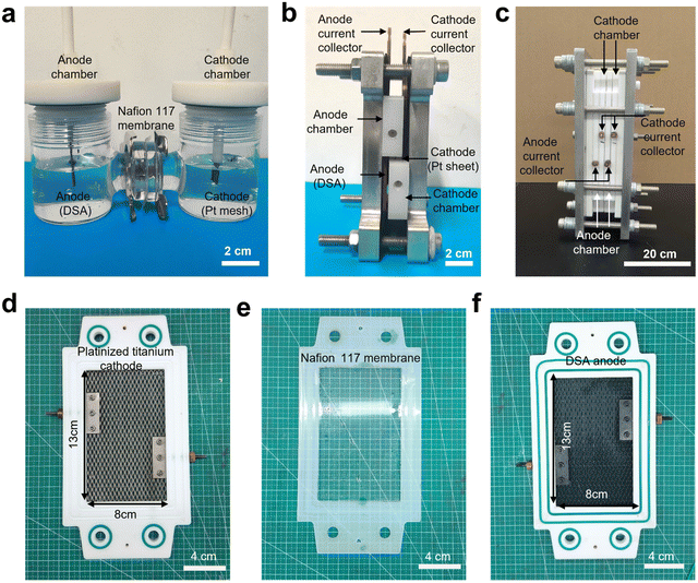
Next, to validate the practical applicability of this technology, we conducted scale-up experiments in a laboratory setting. We designed and fabricated an electrochemical flow cell with an effective electrode area of 208 cm2 (Fig. 1c, S2, and S3†). An electrosynthesis platform was constructed with a dual-channel circulation peristaltic pump, two jacketed reaction vessels for holding the anolyte and catholyte, and a direct current (DC) power supply for driving the electrolysis (Fig. 2a). Based on the optimal conditions obtained from the small-scale flow cell experiments, we increased the 2-MN substrate solution volume by 18-fold from 40 mL in the small-scale flow cell experiment to 750 mL in the large-scale flow cell experiment. The electrooxidation step was carried out at a current of 10 A (50 mA cm−2 current density) and a 180 mL min−1 circulation flow rate. 91% FE was achieved for Ce3+ oxidation, comparable to the electrochemical FE of small-scale reactors. Furthermore, the stability of the large-scale flow cell electrolysis apparatus was evaluated by conducting six consecutive cycles of electrolysis; the FE and voltage remained stable during this prolonged operation (Fig. 2b). The 2-MN oxidation step achieved a 66% yield of the desired 2-MNQ product, similar to the small-scale experiments. These preliminary scale-up study results validated the scalability of the developed cerium-mediated electrochemical–chemical cascade 2-MN oxidation.
With the optimal reaction conditions and scalability validation in hand, we next explored the determinant factors that are essential to the production cost.
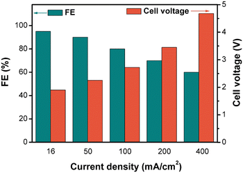
For a given electrochemical system, the applied current density determines the electrolysis FE and cell voltage, which are important factors in the overall electrolysis cost. Thus, we investigated the effects of current density in the small-scale flow cell (Fig. 4). As expected, the FE decreased and the cell voltage increased with increasing current density. Even though a high current density could increase the space–time yield and reduce the capital investment of the electrochemical reactor, it led to decreased electricity efficiency and increased energy cost. Therefore, this correlation of current density with FE and voltage suggests that there is a trade-off between the reactor capital investment and electricity cost when selecting an appropriate current density.
3.2 Technoeconomic analysis
As discussed in the Introduction section, production cost and environmental sustainability are the two key driving factors for replacing existing manufacturing processes. For the case of the 2-MNQ synthesis, the cerium-mediated electrosynthesis process shows clear environmental benefits over the existing industrial production route for avoiding the use of carcinogenic chromium. However, the existing literature rarely reported detailed technoeconomic analysis of electroorganic synthesis technology in the field of fine chemical synthesis, leading to the biased preconception that electrosynthesis technology shows a clear economic advantage because traditional oxidants or reductants are replaced by cheaper electrons from electricity.1,2,4 To form an objective assessment of the technoeconomic aspect of the emerging electrosynthesis technology, we first analyzed all associated cost for an electrosynthesis process, and then projected the future cost reduction trend by considering the continuing technological development in electrodes, membranes, and renewable electricity generation.Based on the results of electrolysis experiments and the oxidation of 2-MN, we designed the production flowchart for cerium-mediated electrosynthesis of 2-MNQ. The spent cerium salts were recycled via simple liquid–liquid phase separation. To evaluate the practical feasibility of the proposed approach (Scheme 2), we conducted experiments on cerium salt recovery. After completing the reaction, the reaction mixture underwent extraction and separation, achieving a recovery rate of 98% in the aqueous phase (ESI† section S5), validating the potential viability of cerium recycling. Based on this production scheme, we calculated the reagent cost and electrolysis cost per ton of 2-MNQ produced (Table 1). We found that in this study, the electrolysis cost accounts for 28.2% of the total cost. However, compared to the reagent cost, the electrolysis cost can be reduced by optimizing electrolysis conditions and equipment, replacing electrodes to improve FE and reduce cell voltage, thus lowering the electrolysis cost. Therefore, in subsequent analysis, we will use this result as a basis and focus on studying the influence of various factors on electrolysis costs.
| Cost components | Item | Unit priceb | Costc (per ton2-MNQ) | Percentage | Notes |
|---|---|---|---|---|---|
| a Assuming an annual production of 400 tons of 2-MNQ and 300 production days per year. b The unit price for reagents and solvents was found on reagent websites, which did not necessarily represent the cost sourced from industrial suppliers. c The cost refers to the price corresponding to the production of each ton of 2-MNQ. d Equipment refers to electrolysis equipment excluding electrodes and ion exchange membranes. It includes necessary flow cells, tubing, control equipment, circulation pumps, and other related devices for electrolysis. | |||||
| Reagent cost | 2-MN | $3099 per t | $4352 | 46.5% | The cost was calculated by a yield of 60%. The price of 2-MN was from Chemicalbook (https://www.chemicalbook.com). The conversion was 100% |
| Ce2(CO3)3·8.5H2O | $915 per t | $817 | 8.7% | 10 equivalents Ce4+ was used. Considering that cerium salts can be recycled, we assumed a recycling recovery rate of 97%. The price of Ce2(CO3)3·8.5H2O was from https://www.cbcie.com | |
| MeSO3H | $1971 per t | $1676 | 17.9% | 50.6 equivalents MeSO3H was used. Considering that MeSO3H did not participate in the reaction, we assumed a recycling recovery rate of 99%. The price of MeSO3H was from Chemicalbook (https://www.chemicalbook.com) | |
| DCE | $422 per t | $258 | 2.8% | The substrate concentration was 0.2 M. The solvent recovery rate was assumed to be 98%. The price of DCE was from Chemicalbook (https://www.chemicalbook.com) | |
| Electrolysis cost | Equipmentd | $7042 per m2 | $375 | 4.0% | The price of the equipment was from Suzhou Fenggang Titanium Products and Equipment Manufacturing Co., Ltd. According to the literature and recommendations from equipment manufacturers, we assumed the lifespan of the electrochemical flow cells to be 15 years.41,42 |
| Anode (DSA) | $1830 per m2 | $489 | 5.2% | The price of DSA was from Baoji Boruicheng Titanium Industry Co., Ltd. We conservatively assumed the service life of DSA to be 3 years | |
| Cathode (platinized titanium) | $1830 per m2 | $244 | 2.6% | The price of platinized titanium was from Baoji Boruicheng Titanium Industry Co., Ltd. We conservatively assumed the lifespan of platinized titanium electrode to be 5 years | |
| Membrane (Nafion 117) | $3239 per m2 | $518 | 5.5% | The price of the Nafion117 membrane was from https://www.scimaterials.cn. According to reports, membranes in the chlor-alkali industry are replaced every four to five years.43 Here, we conservatively assumed the lifespan of the membranes to be 5 years | |
| Electricity | $0.1 per kW h | $637 | 6.8% | The electrolysis parameters were 50 mA cm−2 current density, 2.2 V cell voltage, and 90% FE | |
| Total | $9366 | 100% | |||
3.3 Future economic projection of the electrosynthesis
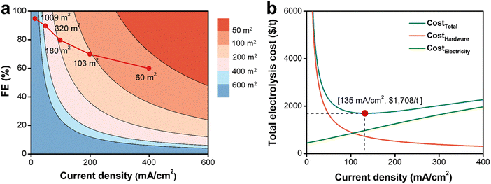
In this section, we focused on discussing how the production cost will be affected by the future technological advancement of electrosynthesis.Based on the results of Ce3+ electrooxidation, increasing current density and FE can rapidly decrease the electrochemical flow cell size as shown by the red line in Fig. 6a. When the current density increases from 50 mA cm−2 to 400 mA cm−2, the electrode area decreases from 320 m2 to 60 m2 for 400 t annual production volume of 2-MNQ. When projecting the electrocatalysts or electrode material technology continuing to improve in the future, it is expected that the electrochemical flow cell size could continue to decrease, thus further reducing CostHardware.
Cell voltage and FE are the determinant factors for the electricity cost. For a given electrocatalytic system, cell voltage and undesired electrode reactions are usually positively dependent on the current density as investigated in section 3.1.2 above. This dependence implies that, without electrocatalysis advancement, it may lead to increased electricity cost when the current density keeps increasing. Thus, there is a trade-off between electricity cost and hardware cost.
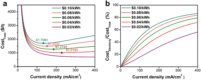
Based on case of the Ce3+ electrooxidation, when the current density reaches 135 mA cm−2, the total electrolysis cost (CostTotal) reaches its minimum value ($1708 per t) (Fig. 6b). A current density lower than 135 mA cm−2 will require to invest a large electrolysis apparatus, while on the other hand, a higher current density leads to increased cell voltage and decreased FE, thus increasing electricity costs. In addition, even though not considered here, a large current density would typically undermine the stability or lifespan of electrodes and membranes, which increases the hardware cost. Therefore, finding an optimal current density to operate at is the critical task during the electrosynthetic engineering towards practical application.
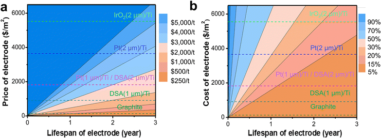
Electrodes, especially anodes, are consumable in the industrial electrosynthesis production, and thus, it is necessary to consider the frequency and cost of replacement. For example, even though graphite is susceptible to anodic corrosion due to its narrow oxidation potential window, it is inexpensive and widely used as an anode in various processes, such as electrolytic aluminum production and paired electrosynthesis for formation of methyl phthalate and 4-(t-butyl)benzaldehyde dimethylacetal.48–50 Precious metal or metal oxide electrodes, such as Pt, iridium(IV) oxide (IrO2), and DSA, can tolerate high oxidation potential and exhibit good corrosion resistance, but they come at a high cost. A comprehensive evaluation of the electrode price and lifespan is necessary to determine the practical electrode cost. Therefore, it is necessary to first analyze the proportion of electrode costs in the total cost, and then analyze the balance between price and lifespan to identify the optimal electrode choice for the actual production.
Here, we explored the contribution of the electrode price and electrode lifespan to the overall electrolysis cost for Ce3+ electrooxidation. Since the cathodic reaction is the hydrogen evolution reaction (HER), the requirement for the cathode is significantly less stringent than that for the anode. Thus, we focused on the analysis of the anode here. Based on reported electrode materials used for Ce3+ electrooxidation,51,52 we investigated graphite, Pt, IrO2, and DSA as the anode materials. Due to the high cost of precious metal or metal oxides, they are usually deposited as a thin layer coating on the titanium (Ti) support. Typically, a thicker active layer coating on the Ti electrode would result a better electrode lifespan, but with a higher cost. For example, a 2 μm DSA coated titanium anode is almost twice the price of 1 μm DSA/Ti. The deactivation mechanism of these coated electrodes usually involves dissolution or detachment of the coated electroactive layer, leaving the titanium base metal uncovered to quickly form nonconductive titanium dioxide (TiO2), thus preventing it from further corrosion.53,54 The deactivated base Ti electrode can be refurbished and re-coated for recycled use. As shown in Fig. 7a, the electrode cost per ton of 2-MNQ synthesized is proportional to the electrode price and negatively correlated to the electrode lifespan. The proportion of electrode cost in the overall electrolysis cost is highly sensitive to the electrode cost and lifespan, thus developing low-cost and stable anode materials is critical in reducing the electrolysis cost.
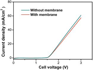
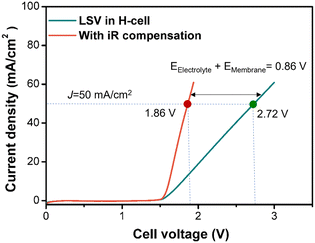
| Ecell = E° + η + I(RElectrolyte + RMembrane) |
In the H-cell, at a current density of 50 mA cm−2, the ohmic voltage drop reached 0.86 V (Fig. 8), accounting for 31.6% of the total cell voltage, representing a significant energy loss to ohmic heat. As the current density increases, the proportion of ohmic energy loss further increases. Hence, it is critical to design and use an electrochemical flow cell that has a minimal interelectrode distance, especially for processes operating at high current densities with low-conductivity electrolytes. A parallel plate electrochemical flow cell can achieve submillimeter interelectrode distances,15,16 which can be stacked to further increase the space–time yield. However, small interelectrode spacing would lead to an increased fluidic pressure drop through the cell channels, increasing the requirements for cell structural rigidity and sealing. On the other hand, small interelectrode spacing would increase the linear velocity across the electrode interface if the volumetric flow rate was kept constant. This could enhance the mass transfer of species towards the electrode surface, which is an important factor for reducing the concentration overpotential (ηconcentration). Thus, in practical production, optimizing and improving the reactor structure according to the reaction characteristics are of great significance for reducing electrolysis costs.
Therefore, we focused on analyzing the trend in overall electrolysis costs as electricity prices decrease. From Fig. 9a, when the electricity price decreases from the current $0.10 per kW h to $0.04 per kW h, the lowest CostTotal decreases from $1708 per t to $1019 per t. With further reduction in electricity price below $0.02 per kW h, it is interesting to find that decreasing the current density always reduces CostTotal. This observation indicates that the drawbacks of increasing cell voltage and decreasing FE brought by increasing current density become less significant as electricity price decreases. With extremely low electricity prices, it is always beneficial to increase the current density. However, it is worth noting that we did not consider the influence of current density on the lifespan of the electrode and membrane here. In terms of the percentage of CostElectricity in CostTotal (Fig. 9b), the cost of electricity becomes a minor contribution factor to the overall electrolysis process as the electricity price decreases. Thus, in the field of electrosynthesis technology for fine chemical production, it will become increasingly important to focus on developing low-cost and stable electrodes and membranes to reduce the CostHardware as they are the dominant cost factor.
4. Conclusions
In summary, this study systematically investigated a cerium-mediated electrochemical–chemical cascade strategy for environmentally friendly and safe production of 2-MNQ. We also constructed a scaled-up electrochemical flow cell with 208 cm2 electrode size to demonstrate the practical scalability of 2-MN oxidation to produce 2-MNQ under optimal conditions. At a scale of 840 mL 2-MN oxidation experiment (240 ml DCE solution, 600 mL Ce4+/Ce3+ aqueous solution), the yield of 2-MNQ was 66%. Using 2-MN electrooxidation as a case study, we calculated the various costs associated with the electrochemical preparation of 2-MNQ. In addition, we systematically explored the effects of factors such as current density, electricity cost, electrode price, and lifespan on the total electrolysis cost, which could serve as a guideline for the community to objectively evaluate the economic driving force to implement electrosynthesis technology in practice. Looking forward, the practical implementation of electrosynthesis still requires the continuing improvement of electrode materials, membranes, and electrochemical reactors, such that the production cost could be further reduced. Moreover, discovering new reactions that are challenging using conventional chemistry methods is also key to creating more opportunities for electrosynthesis to be used in practice.Data availability
The data supporting this article have been included as part of the ESI.†Conflicts of interest
The authors declare no competing financial interest.Acknowledgements
This work was supported by Zhejiang Medicine Co., Ltd. We also thank the support from the National Natural Science Foundation of China (22478335, 22227812, and 22108242) and the National Key R & D Program of China (2021YFA1502700).Notes and references
- Y. Mo, Z. Lu, G. Rughoobur, P. Patil, N. Gershenfeld, A. I. Akinwande, S. L. Buchwald and K. F. Jensen, Science, 2020, 368, 1352–1357 CrossRef CAS PubMed.
- Y. Chen, Y. He, Y. Gao, J. Xue, W. Qu, J. Xuan and Y. Mo, Science, 2024, 384, 670–676 CrossRef CAS.
- X. Lin, S. N. Zhang, D. Xu, J. J. Zhang, Y. X. Lin, G. Y. Zhai, H. Su, Z. H. Xue, X. Liu, M. Antonietti, J. S. Chen and X. H. Li, Nat. Commun., 2021, 12, 3882 CrossRef CAS PubMed.
- L. F. T. Novaes, J. Liu, Y. Shen, L. Lu, J. M. Meinhardt and S. Lin, Chem. Soc. Rev., 2021, 50, 7941–8002 RSC.
- Q. Yang and Y. Mo, Ind. Eng. Chem. Res., 2023, 62, 19427–19436 CrossRef CAS.
- J. A. Marko, A. Durgham, S. L. Bretz and W. Liu, Chem. Commun., 2019, 55, 937–940 RSC.
- Z. Li, C. Liu, W. Geng, J. Dong, Y. Chi and C. Hu, Chem. Commun., 2021, 57, 7430–7433 RSC.
- G.-Q. Sun, P. Yu, W. Zhang, W. Zhang, Y. Wang, L.-L. Liao, Z. Zhang, L. Li, Z. Lu, D.-G. Yu and S. Lin, Nature, 2023, 615, 67–72 CrossRef CAS PubMed.
- W. Zhang, L. Lu, W. Zhang, Y. Wang, S. D. Ware, J. Mondragon, J. Rein, N. Strotman, D. Lehnherr, K. A. See and S. Lin, Nature, 2022, 604, 292–297 CrossRef CAS PubMed.
- Q. Yang, C. Zhang, B. Dong, Y. Cui, F. Wang, J. Cai, P. Jin and L. Feng, Appl. Catal., B, 2021, 296, 120359 CrossRef CAS.
- L. Zhang and X. Hu, Chem. Sci., 2020, 11, 10786–10791 RSC.
- B. Zhu, B. Dong, F. Wang, Q. Yang, Y. He, C. Zhang, P. Jin and L. Feng, Nat. Commun., 2023, 14, 1686 CrossRef CAS PubMed.
- M. Brachi, W. El Housseini, K. Beaver, R. Jadhav, A. Dantanarayana, D. G. Boucher and S. D. Minteer, ACS Org. Inorg. Au, 2024, 4, 141–187 CrossRef CAS.
- W.-F. Huang and M.-C. Yang, Ind. Eng. Chem. Res., 2021, 60, 13180–13190 CrossRef CAS.
- F. Beck, J. Appl. Electrochem., 1972, 2, 59–69 CrossRef CAS.
- D. E. Danly, J. Electrochem. Soc., 1984, 131, 435C–442C CrossRef.
- P. De Luna, C. Hahn, D. Higgins, S. A. Jaffer, T. F. Jaramillo and E. H. Sargent, Science, 2019, 364, eaav3506 CrossRef CAS PubMed.
- D. M. Heard and A. J. J. Lennox, Angew. Chem., Int. Ed., 2020, 59, 18866–18884 CrossRef CAS PubMed.
- L. Yun, J. Zhao, X. Tang, C. Ma, Z. Yu and Q. Meng, Org. Process Res. Dev., 2021, 25, 1612–1618 CrossRef CAS.
- M. M. Heravi, V. Zadsirjan, E. Kouhestanian and B. AlimadadiJani, Chem. Rec., 2020, 20, 273–331 CrossRef CAS PubMed.
- J. Sisler, S. Khan, A. H. Ip, M. W. Schreiber, S. A. Jaffer, E. R. Bobicki, C.-T. Dinh and E. H. Sargent, ACS Energy Lett., 2021, 6, 997–1002 CrossRef CAS.
- B. Ding, Y. Ding, J. Peng, J. Romano-deGea, L. E. K. Frederiksen, H. Kanda, O. A. Syzgantseva, M. A. Syzgantseva, J.-N. Audinot, J. Bour, S. Zhang, T. Wirtz, Z. Fei, P. Dörflinger, N. Shibayama, Y. Niu, S. Hu, S. Zhang, F. F. Tirani, Y. Liu, G.-J. Yang, K. Brooks, L. Hu, S. Kinge, V. Dyakonov, X. Zhang, S. Dai, P. J. Dyson and M. K. Nazeeruddin, Nature, 2024, 628, 299–305 CrossRef CAS.
- Q. Lv, X.-D. Wang, Y. Yu, C.-F. Xu, Y.-J. Yu, X.-Y. Xia, M. Zheng and L.-S. Liao, Nat. Chem., 2024, 16, 201–209 CrossRef CAS PubMed.
- J.-H. Tian, R. Lacroix, A. A. Yaqoob, C. Bureau, C. Midoux, E. Desmond-Le Quéméner and T. Bouchez, Energies, 2023, 16(2), 591 CrossRef CAS.
- Q. Yang, B. Zhu, F. Wang, C. Zhang, J. Cai, P. Jin and L. Feng, Nano Res., 2022, 15, 5134–5142 CrossRef CAS.
- Y. Sun, X. Li, M. Yang, W. Xu, J. Xie and M. Ding, Green Chem., 2020, 22, 7543–7551 RSC.
- Y. Yu, Q. Zhang, J. Li, L. Xu and G. Liu, New J. Chem., 2023, 47, 6155–6163 RSC.
- J. Steinmeier and R. Dringen, Neurochem. Res., 2019, 44, 1167–1181 CrossRef CAS PubMed.
- F. Shi, M. K. Tse and M. Beller, Adv. Synth. Catal., 2007, 349, 303–308 CrossRef CAS.
- W. Adam, J. Lin, C. R. Saha-Möller, W. A. Herrmann, R. W. Fischer and J. D. G. Correia, Angew. Chem., Int. Ed., 1995, 33, 2475–2477 CrossRef.
- S.-I. Murahashi, N. Miyaguchi, S. Noda, T. Naota, A. Fujii, Y. Inubushi and N. Komiya, Eur. J. Org. Chem., 2011, 2011, 5355–5365 CrossRef CAS.
- F. Zhang, X. Li, Y. Tang, X. Gao, L. Xu and G. Liu, Can. J. Chem. Eng., 2016, 94, 1184–1190 CrossRef CAS.
- M. H. Zhou, T. F. Yan, H. Y. Zhu and G. M. Xiao, Adv. Mater. Res., 2013, 634–638, 664–668 Search PubMed.
- S. Yamazaki, Tetrahedron Lett., 2001, 42, 3355–3357 CrossRef CAS.
- D. V. Eremin and L. A. Petrov, Russ. J. Appl. Chem., 2009, 82, 866–870 CrossRef CAS.
- D. S. Achrekar, J. Emerging Technol. Innovative Res., 2022, 9, JETIR2203631 Search PubMed.
- Rare Metal Technology 2018, ed. H. Kim, B. Wesstrom, S. Alam, T. Ouchi, G. Azimi, N. R. Neelameggham, S. Wang and X. Guan, Springer International Publishing, Cham, 2018 Search PubMed.
- S. Niu, T. Tang, Y. Qu, Y. Chen, H. Luo, H. Pan, W.-J. Jiang, J. Zhang and J.-S. Hu, CCS Chem., 2024, 6, 137–148 CrossRef CAS.
- E. A. Toledo-Carrillo, M. García-Rodríguez, L. M. Sánchez-Moren and J. Dutta, Sci. Adv., 2024, 10, eadi3180 CrossRef CAS PubMed.
- H. Chen, X. Zhao, T. Zhang and P. Pei, Energy Convers. Manage., 2019, 182, 282–298 CrossRef CAS.
- O. Schmidt, A. Gambhir, I. Staffell, A. Hawkes, J. Nelson and S. Few, Int. J. Hydrogen Energy, 2017, 42, 30470–30492 CrossRef CAS.
- A. Franco and C. Giovannini, Sustainability, 2023, 15, 16917 CrossRef CAS.
- F. Franco, J. Prior, S. Velizarov and A. Mendes, Appl. Sci., 2019, 9, 284 CrossRef CAS.
- A. Li, S. Kong, K. Adachi, H. Ooka, K. Fushimi, Q. Jiang, H. Ofuchi, S. Hamamoto, M. Oura, K. Higashi, T. Kaneko, T. Uruga, N. Kawamura, D. Hashizume and R. Nakamura, Science, 2024, 384, 666–670 CrossRef CAS PubMed.
- S. J. Cobb, V. M. Badiani, A. M. Dharani, A. Wagner, S. Zacarias, A. R. Oliveira, I. A. C. Pereira and E. Reisner, Nat. Chem., 2022, 14, 417–424 CrossRef CAS.
- T. Zheng, M. Zhang, L. Wu, S. Guo, X. Liu, J. Zhao, W. Xue, J. Li, C. Liu, X. Li, Q. Jiang, J. Bao, J. Zeng, T. Yu and C. Xia, Nat. Catal., 2022, 5, 388–396 CrossRef CAS.
- S. Pan, H. Li, D. Liu, R. Huang, X. Pan, D. Ren, J. Li, M. Shakouri, Q. Zhang, M. Wang, C. Wei, L. Mai, B. Zhang, Y. Zhao, Z. Wang, M. Graetzel and X. Zhang, Nat. Commun., 2022, 13, 2294 CrossRef CAS.
- S. Mao and Q. Zhang, Front. Mater., 2021, 8, 719563 CrossRef.
- Y. Zhu, Y. He and D. Wang, Electrochem. Solid-State Lett., 2011, 14, E25 CrossRef CAS.
- C. A. Paddon, M. Atobe, T. Fuchigami, P. He, P. Watts, S. J. Haswell, G. J. Pritchard, S. D. Bull and F. Marken, J. Appl. Electrochem., 2006, 36, 617–634 CrossRef CAS.
- F. C. Walsh, C. P. de Léon, L. Berlouis, G. Nikiforidis, L. F. Arenas-Martínez, D. Hodgson and D. Hall, ChemPlusChem, 2015, 80, 288–311 CrossRef CAS.
- F. C. Walsh, C. P. de Léon, L. Berlouis, G. Nikiforidis, L. F. Arenas-Martínez, D. Hodgson and D. Hall, ChemPlusChem, 2015, 80, 288–311 CrossRef CAS.
- Z. Deng, S. Xu, C. Liu, X. Zhang, M. Li and Z. Zhao, Nano Res., 2024, 17, 949–959 CrossRef CAS.
- T. Loucka, J. Appl. Electrochem., 1981, 11, 143–144 CrossRef CAS.
- G. Glenk and S. Reichelstein, Nat. Energy, 2019, 4, 216–222 CrossRef CAS.
- D. Han, J. Wang, L. Agosta, Z. Zang, B. Zhao, L. Kong, H. Lu, I. Mosquera-Lois, V. Carnevali, J. Dong, J. Zhou, H. Ji, L. Pfeifer, S. M. Zakeeruddin, Y. Yang, B. Wu, U. Rothlisberger, X. Yang, M. Grätzel and N. Wang, Nature, 2023, 622, 493–498 CrossRef CAS PubMed.
- R. Lin, Y. Wang, Q. Lu, B. Tang, J. Li, H. Gao, Y. Gao, H. Li, C. Ding, J. Wen, P. Wu, C. Liu, S. Zhao, K. Xiao, Z. Liu, C. Ma, Y. Deng, L. Li, F. Fan and H. Tan, Nature, 2023, 620, 994–1000 CrossRef CAS PubMed.
- Y. Karneyeva and R. Wüstenhagen, Energy Policy, 2017, 106, 445–456 CrossRef.
- J. Yan, Y. Yang, P. Elia Campana and J. He, Nat. Energy, 2019, 4, 709–717 CrossRef CAS.
- P. Albertus, J. S. Manser and S. Litzelman, Joule, 2020, 4, 21–32 CrossRef CAS.
- Levelized cost and Levelized avoided cost of new generation resources in the annual energy Outlook 2019, U.S. Energy Information Administration, 2019, https://www.eia.gov/outlooks/aeo/pdf/electricity_generation.pdf Search PubMed.
Footnote |
| † Electronic supplementary information (ESI) available. See DOI: https://doi.org/10.1039/d4re00346b |
| This journal is © The Royal Society of Chemistry 2025 |

