
 Open Access Article
 This Open Access Article is licensed under a Creative Commons Attribution-Non Commercial 3.0 Unported Licence
An efficient and flexible approach for local distortion: distortion distribution analysis enabled by fragmentation†
Zeyin
Yan‡
 ,
Yunteng Sam
Liao‡
,
Xin
Li
and
Lung Wa
Chung
*
,
Yunteng Sam
Liao‡
,
Xin
Li
and
Lung Wa
Chung
*
Shenzhen Grubbs Institute, Department of Chemistry, Guangdong Provincial Key Laboratory of Catalysis, Southern University of Science and Technology, Shenzhen 518055, China. E-mail: oscarchung@sustech.edu.cn
First published on 23rd December 2024
Abstract
Distortion can play crucial roles in influencing structures and properties, as well as enhancing reactivity or selectivity in many chemical and biological systems. The distortion/interaction or activation-strain model is a popular and powerful method for deciphering the origins of activation energies, in which distortion and interaction energies dictate an activation energy. However, decomposition of local distortion energy at the atomic scale remains less clear and straightforward. Knowing such information should deepen our understanding of reaction processes and improve reaction design. Herein, an efficient, general and flexible fragmentation-based approach was proposed to evaluate local distortion energies for various chemical and biological molecules, which can be obtained computationally and/or experimentally. Moreover, our distortion analysis is readily applicable to multiple structures from molecular dynamics (or the minimum energy path) as well as can be evaluated by different computational chemistry methods. Our systematic analysis shows that our approach not only aids computational and experimental chemists in visualizing (relative) distortion distributions within molecules (distortion map) and identifies the key distorted pieces, but also offers deeper understanding and insights into structures, reaction mechanisms and dynamics in various chemical and biological systems. Furthermore, our analysis offers indices of local distortion energy, which can potentially serve as a new descriptor for multi-linear regression (MLR) or machine learning (ML) modelling.
Introduction
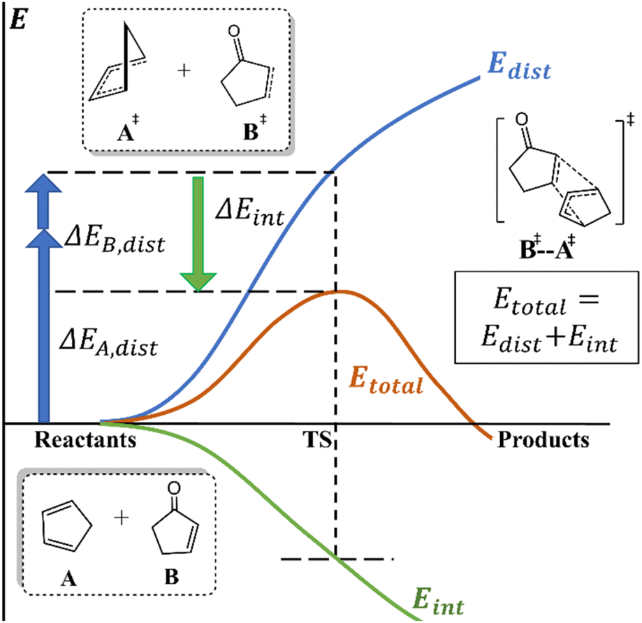
Understanding chemical processes (such as reaction mechanisms, kinetics, and selectivity) has been of paramount importance, helping chemists to rationally design catalysts and optimize reactions. Numerous theories and models have also been developed to provide valuable explanations and insights for understanding and improving reactions. For instance, pioneering theories, such as transition state theory (TST)1 and Marcus theory,2 have laid the vital groundwork for understanding chemical kinetics. Additionally, orbital-based theories, such as frontier molecular orbital (FMO),3 Woodward–Hoffmann rule,4 valence bond (VB),5 natural bond orbital (NBO),6,7 intrinsic bond orbital (IBO),8 and principal interacting orbital (PIO) theories,9 offer more intuitive insights and analysis of reactions from an orbital perspective.Notably, deformation/interaction, distortion/interaction and activation-strain models pioneered by the Morokuma, Houk and Bickelhaupt groups10–14 are popular and powerful methods for deciphering the origin of activation energies.15,16 This model decomposes an activation energy (or relative electronic energy along the reaction coordinate (ζ);17 ΔE± or ΔE(ζ), respectively) into distortion energy (Edist) of the reactant fragments (A and B) and their interaction energy (Eint, Scheme 1). This approach has been successfully and widely applied to various homogeneous and biological systems.18,19
 | ||
| Scheme 1 Distortion/interaction and activation-strain models. | ||
When the interaction energy contribution is crucial, various components of interactions can be further analyzed and quantified by energy decomposition analysis (EDA)20 and its variants.21–28 Additionally, to analyze, identify or correct noncovalent interactions (NCIs), diversified methods and tools (e.g., reduced density gradient,29 dispersion interaction potential30 and classical dispersion correction31) were also developed. Moreover, Fukui functions,32 conceptual density functional theory,33 quantum theory of atoms in molecules (QTAIM),34 electrostatic potential maps,35 steric maps36 and Sterimol37,38 have been widely utilized to gain insights into electronic or steric effects on chemical systems.39
Despite the development of many methods and tools to analyze and decompose interaction energy, detailed analysis and tools for distortion energy (also known as deformation or strain energy40) have received much less attention. It should be noted that distortion energy has played important roles in affecting some structures and properties as well as promoting some reactivity or selectivity.41–56 What's more, distortion energy is regarded as a global property of a molecule, whereas the local atomic geometry should collectively determine the (global) distortion energy of the molecule. However, the distribution/decomposition of (local) distortion energy at the atomic scale is less clear or straightforward. Acquisition of such information should enhance our understanding on the reaction processes.
To address this issue, the Dreuw group developed a seminal method (so-called JEDI) to evaluate and visualize distortion in mechanochemical systems, based on the quantum-mechanics (QM)-computed Hessian matrix using redundant internal coordinates and harmonic approximation.57 In addition, the Jasti group elegantly developed a strain-visualization method (StrainViz) for macrocycles specifically by combining isodesmic reaction, iterative fragmentation and integrating forces released into each internal coordinate during geometry optimization of each fragment.58 These two methods have been successfully applied to a few specific systems and illustrated the local distortion distribution.59–61 However, the computational cost of Hessian for medium and large systems is expensive, especially for some computational chemistry methods lacking analytic Hessian. Moreover, the Houk group proposed and conducted ad hoc fragmentation to evaluate distortion energies of a few fragments for a few intramolecular reactions.62,63
To elucidate the (relative) distortion distribution of various systems at different stages (e.g. stationary points, and/or any non-stationary-point structures from intrinsic reaction coordinate (IRC) or molecular dynamics (MD) simulations; or experimentally determined structures), an efficient, general and flexible fragmentation-based approach (Distortion Distribution Analysis enabled by Fragmentation, D2AF) was proposed to qualitatively estimate local distortion energies for various chemical and biological molecules. Our approach not only helps computational and experimental chemists to visualize distortion energy distribution within molecules (i.e. distortion map) and identify the key distorted part(s), but also provides values of local distortion energy, that can also be used as a new descriptor for statistical (e.g. multi-linear regression, MLR) or machine learning (ML) analysis/models.64
Methodology
As outlined in Fig. 1, our fragmentation-based approach consists of three stages: fragmentation, calculations, and visualization. The users first provide two structures: target molecule (Tar; usually with more distortion) and its reference (Ref) form. Computed local distortion energy within a molecule is derived from the energy difference between the reference and target forms for each fragment. In addition, the local distortion energy can be determined and categorized by one of three approaches (M1–M3) with different fragmentation and coordinate manipulation schemes, depending on the purpose and system's complexity. The main features of these three approaches are summarized in the main text (see below), while the detailed description and discussion are given in the ESI.† | ||
| Fig. 1 Our workflow of distortion distribution analysis with fragmentation (D2AF). (a) The input structures contain the target system (Tar) and its reference (Ref) form. (b) Schematic fragmentation and coordinate manipulation methods (M1–M3). (c) ONIOM-type link atom (LA) treatment. (d) Energy calculations of fragments. (e) Distortion map visualization. | ||
Method 1 (M1) scheme
Following many-body expansion approximation prevalently used in many fragmentation schemes,65–70 the total energy difference (Ediff) between the target (Tar) and reference (Ref) molecules can similarly be estimated using the fragmentation energy difference as in eqn (1). | (1) |
| Edistort,i = ETari − ERefi | (2) |
The size of fragments in this M1 method can be varied from the smallest possible fragment(s) (e.g., one heavy atom and its link atom(s)) to larger fragment(s) (including conjugate groups, e.g. aromatic rings or alkenyl/alkynyl) customized by the users. The minimum possible number of heavy atoms included in each fragment is often adopted to gain higher “resolution” of the distortion map and reduce the computational cost, if the key bonding interactions can be captured within the fragment.
Method 2 (M2) scheme
Analogous to molecular mechanics, alternative fragmentation and decomposition of the distortion energy into three bonding terms (Ebond, Eangle and, optionally, Edihedral) relating to each internal coordinate can be summarized in eqn (3). To achieve such distortion decomposition, fragmentation including two, three or four heavy atoms (together with their link atom(s)) for one target internal coordinate (bond, angle or dihedral, respectively) taken from the reference form is first performed to generate the Ref fragments. Then, only one target internal coordinate of each generated fragment is altered to be identical to that coordinate value in the target system to set up all combinations of the Tar fragments (Fig. 1b and Scheme S2†). Accordingly, in contrast to the M1 method, local distortion of each bonding coordinate within one fragment is evaluated individually.| ΔEdistort ≈ ∑ΔEbond + ∑ΔEangle + ∑ΔEdihedral | (3) |
Method 3 (M3) scheme
Since some improper fragmentation in M2 can neglect some important electronic effects (such as delocalization or lone pair repulsion), when dealing with such complex conjugated systems, a hybrid partition (M3) is applied for two different situations: any delocalized conjugated moiety using M1 and the rest of the localized part using M2 (Scheme S2†). Moreover, for challenging metal coordination systems, their complex metal–ligand interactions are hardly decomposed. These new hybrid features in M3 allow the users to define a minimum metal–ligand coordination region as one special fragment to capture the key metal–ligand interactions using M2, while the remaining parts can be evaluated using M1 and/or M2 (Scheme S3†).Link-atom treatment
Fragmentation processes generally need to introduce link atoms (LAs) to cap all dangling bonds in all generated fragments, when a boundary involving single, double or triple bond is broken. The ONIOM-type boundary and LA approach are adopted.71,72 Therefore, the position of the link atom is not fixed, but depends on the bond distance of the two boundary atoms (Fig. 1c). A systematic benchmark study of the reliability of different link atoms was conducted (see Fig. S1–S16† for details). These results suggested that H-LA, C-LA, and N-LA were generally applied for boundaries involving single, double, and triple bonds, respectively, unless otherwise specified.Calculations
Energies of all generated fragments can then be computed using user-specified quantum-mechanics (QM) or machine-learning potential (MLP) method(s) and programs (Fig. 1d). Our current Python package interfaces a few QM and MLP programs (e.g., Gaussian,73 ORCA,74 xTB,75 TorchANI,76 and MLatom77). Alternatively, users can use their scripts to prepare input files for a specific program and method, call QM calculations and extract the QM-computed energy of each fragment.Analysis and visualization
After the energy calculations of each fragment, the distortion energy for the individual target and reference fragments can be determined on the basis of the M1–M3 schemes. All distortion energies are recorded in an Excel file. Additionally, PyMOL scripts are generated to visualize the distribution of (relative) distortion energy (distortion map, Fig. 1e). Moreover, fragments in M1 are colored according to their corresponding local distortion energies, whereas, the local distortion energies in M2 can be further decomposed into specific bonding terms, and all bonds are color-coded based on the cumulative distortion energy contribution from all internal coordinates.Computational details
All these calculations were performed using our open-source python package (D2AF, https://github.com/oscarchung-lab/D2AF), which employs the Open Babel package to treat internal coordinates of fragments.78 The choice of the DFT method and basis sets as well as structures for each application system in this study were taken from the original studies (unless stated otherwise). All DFT calculations were conducted by Gaussian 16D1.73 In addition, calculations using other computational methods for a few systems were also carried out: GFN2-xTB as a semi-empirical method (SE) by xTB-python,75 AIQM1 by MLatom 3.0,77,79 and ANI-series by TorchANI80,81 as MLPs, as well as CCSD(T)/cc-pVTZ by ORCA 5.0.74,82 (Relative) distortion distributions (distortion map) were visualized by using PyMOL.83Results and discussion
In order to demonstrate the robustness and broad applicability of our approach, a diverse set of chemical and biological systems were systematically investigated. The key results for eight representative systems will be presented in the main text, while their detailed results as well as the results of another 12 systems (including organic, inorganic, supramolecular, metal-coordination and biological systems) are provided in the ESI.† The representative systems presented in the main text can be categorized into different types: (i) organic systems (reverse Cope elimination,63 Diels–Alder cycloaddition,84 azide–alkyne cycloaddition85 and triplet excited-state di-π-methane rearrangement reactions);86,87 (ii) the key part of a supramolecular system (an addition reaction within a macrocycle[2]rotaxane);88 (iii) metal-coordination system (Ir-catalyzed C–H borylation);89 (iv) biological system (a spleen tyrosine kinase protein in complex with an imatinib drug derived from the X-ray crystal structure and our quantum refined structure).90 In addition, multiple structures obtained from MD simulations and IRC calculations of two simple SN2 reactions were also applied to show the change in (relative) distortion distribution during the reaction process.Reverse Cope elimination reaction (organic system)
Fig. 2a presents an intramolecular concerted addition reaction, which involves the addition of the proton and the amine onto the triple bond along with the O–H bond breaking. The Houk group systematically studied this reaction mechanism.63 Their DFT results showed that the main distortion comes from the alkyne (∼17.6 kcal mol−1) and hydroxylamine (∼14.5 kcal mol−1) parts along with some distortion of the tether part (∼8.9 kcal mol−1). Comparatively, our M1 and M2 schemes are also applied to perform detailed analysis of the distortion distribution of this reaction (Fig. 2b–g). Distortion distribution using M1 also supports that the significant distortion originates from the alkyne and hydroxylamine moieties (ΔE(I): ∼17.6 kcal mol−1 and ΔE(II): ∼14.6 kcal mol−1; Fig. 2c). Distortion distribution by M2 generally shows a similar distribution (Fig. 2e), i.e., bending of the triple bond as the main distortion contributor (Δ(A1): −41.9° with a distortion energy of ∼9.6 kcal mol−1; Δ(A2): −19.6° with a distortion energy of ∼3.6 kcal mol−1) and the O–H bond stretching/O–N bond compression in the hydroxylamine part as a significant contribution (Δ(B1): 0.12 Å with a distortion energy of ∼6.3 kcal mol−1; Δ(B2): −0.09 Å with a distortion energy of ∼2.8 kcal mol−1). | ||
| Fig. 2 (a) Overview of a reverse Cope elimination (structures taken from ref. 62). (b) Bond length change (ΔBond in Å) from the reference form (Ref; reactant, S1-R) to the target form (Tar; TS, S1-TS). (c) Distortion distribution (kcal mol−1) and (d) fragmentation using the M1 scheme. (e) Total distortion distribution (kcal mol−1), its distortion contribution from (f) bond and (g) angle terms using the M2 scheme. The major local distortion contributed by the dihedral (D1) was also considered by using an expanded CH2CH2 fragment in the M1 scheme and adding D1 in the M2 scheme. The O–N group was also considered as one fragment in M1. The key geometrical changes and their corresponding distortion energy (ΔE) by the B3LYP/6-31G(d) method are also given. | ||
Moreover, a considerable dihedral change of the tether (Δ(D1): −170.8°) motivated us to include its distortion energy contribution (∼4.9 kcal mol−1) in the M2 scheme and expand one methylene fragment in the M1 scheme. Such unfavourable eclipsed conformation relating to D1 in S1-TS is in agreement with the findings of the Houk group. Consequently, our distortion analysis using the M1 and M2 approaches can reveal a detailed and complementary picture of distortion distribution, which can gain more mechanistic understanding.
Diels–Alder reaction (organic system)
Our second system is a Diels–Alder reaction between cyclopentenone and cyclopentadiene (Fig. 3).84 As illustrated in Fig. 3c and e, our analysis results suggest that the major distortion is primarily contributed by the addition sites. Besides, the Houk group pioneeringly discovered a strong linear correlation between the molecular distortion and activation energy in a series of [4 + 2] addition reactions (R2 = 0.93).84 To further demonstrate the efficacy and usefulness of our analysis, excellent linear correlations between the activation energy and the largest local distortion component (fragment I in the M1 scheme; B1 in the M2 scheme) are also observed (Fig. 3h, R2 ∼ 0.96). | ||
| Fig. 3 (a) Overview of a Diels–Alder cycloaddition (structures taken from ref. 83). (b) Bond length change (ΔBond in Å) from the reference form (Ref; reactant, S2-R) to the target form (Tar; TS, S2-TS). (c) Distortion distribution (kcal mol−1) and (d) fragmentation using the M1 scheme. (e) Total distortion energy distribution (kcal mol−1), its distortion contribution from (f) bond and (g) angle terms using the M2 scheme. (h) Correlation between the computed local distortion energy of the key fragments (B1, I) and activation energy of the Diels–Alder reaction with four different substrates. The key geometrical changes and their corresponding distortion energy (ΔE) by the M06-2X/6-31G(d) method are also given. | ||
As insightfully pointed out by Bickelhaupt and Houk,11 the distortion energy of the two reactant fragments into their transition-state geometries can be related to energy curves in Marcus theory (or analogously two principal-state curves in VB theory91). Therefore, reactivity was suggested to be influenced by thermodynamics (affecting the position of the transition state) and distortion energy. In fact, as also proposed by the Houk group,84 the bending of C–H bonds out of the reacting alkene C![[double bond, length as m-dash]](https://www.rsc.org/images/entities/char_e001.gif) C plane plays the key role in the barrier during the new C–C bond formation, which consistently relates to the largest local distortion component (I). That involves the key bond elongation as well as some pyramidalization (changing hybridization) on the reaction carbon sites, which should be one of the key coordinates and thus controls the barrier. Our results indicate that the main local distortion not only helps understand the main source of the barrier, but also can potentially serve as a new descriptor/feature for multivariate linear regression (MLR) and machine learning (ML) modeling.64
C plane plays the key role in the barrier during the new C–C bond formation, which consistently relates to the largest local distortion component (I). That involves the key bond elongation as well as some pyramidalization (changing hybridization) on the reaction carbon sites, which should be one of the key coordinates and thus controls the barrier. Our results indicate that the main local distortion not only helps understand the main source of the barrier, but also can potentially serve as a new descriptor/feature for multivariate linear regression (MLR) and machine learning (ML) modeling.64
Azide–alkyne cycloaddition (organic system)
Our distortion distribution analysis was also carried out to analyze the strain-promoted [3 + 2] dipolar cycloaddition between azide and strained 2-methyloxyl-cyclooctyne (Fig. 4),85 which is a vital bio-orthogonal reaction.92 As shown in Fig. 4b, the most significant distortion using the M1 scheme was found to be the azide (∼15.3 kcal mol−1) and alkyne (∼4.9 kcal mol−1) moieties. On the other hand, analysis using M2 is not easy to manipulate only one internal coordinate within the cyclic moiety. Instead of M2, the hybrid M3 scheme was thus employed in this cyclic system (Fig. 4e–g). Likewise, our M3 results further support these two major distortion contributors, due to considerable bending of the azide (Δ(A1): −31.5°, ΔE(A1): ∼13.8 kcal mol−1) and N–N bond stretching (Δ(B1): 0.02 Å, ΔE(B1): ∼4.1 kcal mol−1). In addition, bending of the reacting alkyne regions (A2 and A3) contributes to some distortion (∼2.4 and 3.3 kcal mol−1, respectively). | ||
| Fig. 4 (a) Overview of the azide–alkyne cycloaddition (structures taken from ref. 84). (b) Distortion distribution (kcal mol−1) and (c) fragmentation using the M1 scheme. (d) Bond length change (ΔBond in Å) from the reference form (Ref; reactant, S3-R) to the target form (Tar; TS, S3-TS). (e) Total distortion distribution (kcal mol−1) (f) distortion contribution from bond and (g) angle terms using the M3 scheme. (h) Analysis using the truncated S3model (extracting from S3-R and S3-TS with keeping only the alkyne part) to compare with the energy for the 2-butyne (S3*) substrate. ΔEact refers to the activation energy for the original S3 substrate. (i) Relative total distortion distribution (kcal mol−1) of S3model-TS with the reference to S3*-TS using the M1 scheme, relative total distortion distribution (kcal mol−1) and its contribution from the angle term using the M3 scheme. The key geometrical changes and their corresponding distortion energy (ΔE) by the SCS-MP2/6-31G(d) method are also given. | ||
To get deeper understanding on this strain-promoted addition, the same reaction with an acyclic alkyne substrate (2-butyne, S3*-R) has also been studied by the same computational method in this work (Fig. 4h). A higher barrier (∼20.6 kcal mol−1) for this acyclic alkyne was found in our calculations, compared to the strained alkyne (∼7.7 kcal mol−1). Notably, our D2AF results highlight that distortion energies of A1 (∼18.9 kcal mol−1) and A2 (∼4.5 kcal mol−1) in S3*-TS are increased relative to the S3*-R substrate, compared to those for S3-TS and S3-R (ΔE(A1): ∼14.6 kcal mol−1 and ΔE(A2): ∼2.8 kcal mol−1).
To further compare with the strained alkyne (S3-R), S3model-R and S3model-TS models were generated by truncating S3-R and S3-TS (only keeping the alkyne part) followed by capping with H-LA. Single-point energies on the truncated S3model-R and S3model-TS models give a similar barrier (∼9.6 kcal mol−1), which is comparable to that of the full S3 system (∼7.7 kcal mol−1). Moreover, S3model-R and S3model-TS models were found to have higher distortion energies than those of S3*-R and S3*-TS by roughly ∼16.3 and ∼5.3 kcal mol−1, respectively. Accordingly, much higher distortion energy in the cycloalkyne S3-R reactant (i.e. reactant destabilization or pre-organization effect) should be the key factor in lowering the barrier. In addition, a larger reaction driving force (ΔERXN, partly driven by strain relief)93 for S3model than S3* (−90.7 and −80.4 kcal mol−1, respectively) should be another factor in lowering the barrier and rendering the earlier transition state (with a smaller distortion energy based on the Hammond postulate).
Notably, the relative distortion energy between two related transition states (dictating the selectivity) is generally much smaller than the distortion energy of the transition state with respect to its preceding minimum (determining the barrier). Accordingly, it is harder to identify the source of the distortion energy difference to understand the selectivity, while, our flexible approach conveniently illustrates the major distortion energy difference between the two transition states (Fig. 4i).
Triplet excited-state di-π-methane rearrangement (organic system)
Apart from the previous reaction systems in a closed-shell singlet ground state, a triplet excited-state di-π-methane rearrangement of benzobarrelene involving spins was selected for our distortion analysis (Fig. 5a).86 Our M1 scheme reveals that the key distortion should result from the bridgehead fragment I (Fig. 5c and d, ΔE(I): ∼8.7 kcal mol−1). Likewise, the M3 scheme shows that the C–C–C bending between the two reacting regions (Δ(A1): −15.9°, ΔE(A1): ∼16.7 kcal mol−1) results in the most significant distortion within the molecule (Fig. 5e–g), while stretching of the reacting CC bond (Δ(B1): 0.04 Å) contributes to the trivial distortion (∼1.1 kcal mol−1). Therefore, our analysis points out that the bending angle (A1) plays a pivotal role, which may not straightforwardly be seen. Additionally, these findings highlight a certain capability of our analysis of excited-state systems.
 | ||
| Fig. 5 (a) Overview of the triplet di-π-methane intramolecular rearrangement (structures taken from ref. 86). (b) Bond length change (ΔBond in Å) from the reference form (Ref; reactant, S4-R) to the target form (Tar; TS, S4-TS). (c) Distortion distribution (kcal mol−1) and (d) fragmentation using the M1 scheme. (e) Total distortion distribution (kcal mol−1), distortion contribution from (f) bond and (g) angle terms using the M3 scheme. The key geometrical changes and their corresponding distortion energy (ΔE) by the ωB97X-D/6-31G(d) method are also given. | ||
Cyclization of fumaramide within [2]rotaxane (supramolecular system)
Recently, supramolecular catalysis has attracted more attention.94 We extracted two key intermediate (guest) molecules from our recent study on stereoselective cyclization of fumaramide into trans-β-lactam within [2]rotaxane (Fig. 6).88 Our previous study showed that the stability of the two key intermediates (S5-cis and S5-trans) determined the stereoselectivity, in which the cis intermediate has a larger distortion energy than the trans intermediate by ∼5.0 kcal mol−1. Our distortion distribution of the cis (minor) intermediate is further compared to the trans (major) intermediate (Fig. 6a). In contrast to the abovementioned organic systems, our initial analysis using the M1 or M3 (considering contribution from bonds and angles only) scheme shows that the sum of the local distortion energy components (<∼1.0 kcal mol−1) is obviously smaller than the global distortion energy of the whole intermediates (∼5.0 kcal mol−1, Fig. S26 and Table S1†). | ||
| Fig. 6 (a) Overview of the cis and trans isomers of the key intermediate during the CsOH-promoted cyclization (structures taken from ref. 88). (b) Bond length change (ΔBond in Å) from the reference form (Ref; S5-trans) to the target form (Tar; S5-cis). (c) Distortion distribution (kcal mol−1) and (d) fragmentation using the M1 scheme. (e) Total distortion distribution (kcal mol−1) (within the rotaxane in grey transparent line representation), distortion contribution from (f) bond, (g) angle and (h) dihedral terms using the M3 scheme. The key geometrical changes and their corresponding distortion energy (ΔE) by the SMD M06/6-311+G(d,p) method are also given. | ||
These results imply that dihedral(s) can be the major distortion contributor, due to the large change in the D1 and D2 dihedrals (Fig. 6, Δ(D1) = 89° and Δ(D2) = 114°). Therefore, a larger fragment I (including D1 and D2 dihedrals) was further treated using the M1 scheme (Fig. 6d). A higher distortion energy of this key fragment (ΔE(I) = ∼7.8 kcal mol−1) is primarily attributed to tremendous differences in the two dihedrals between these two intermediates (Fig. 6a–c). Similarly, upon incorporation of the contribution from these dihedral components using the M3 scheme, these two key dihedrals (D1 and D2) leading to distortion energies of ∼6.0 and ∼4.7 kcal mol−1 are identified (Fig. 6e–h), respectively.
It should be noted that the distortion energy difference between two minima usually is much smaller than the distortion energy difference between a reactant and its corresponding transition state, and thus it is more difficult to recognise the source of the distortion at the atomic scale for the former case. Again, our flexible approach handily exemplifies the major distortion energy difference and confirmed that the trans-stereoselective cyclization is attributed to the higher distortion mainly caused by the two key dihedrals of the cis form enforced by the rotaxane (Fig. 6e). Moreover, those for the two corresponding transition states were analyzed, further providing deeper insights into the selectivity of this reaction at the atomic scale (Fig. S29†).
Ir-catalyzed C–H borylation (metal-coordination system)
Besides the above organic systems, we also performed local distortion analysis on a metal-coordination system (Ir-catalyzed C–H activation involving (bpy)Ir(Beg)3 (bpy: 2,2′-bipyridine; Beg: (ethyleneglycolato)boron) and indole, Fig. 7a).89 It should be noted that fragmentation on metal-coordination systems is scarce and much less straightforward. To maintain complex metal–ligand bonding around the metal center, the Ir and three ligated boron atoms as well as the bpy ligand were set as one specialized fragment (see Scheme S3 and Fig. S30† for the detailed fragments and coordination region). | ||
| Fig. 7 (a) Overview of Ir-catalyzed C–H borylation (structures from ref. 89). (b) Distortion distribution (kcal mol−1) using the M1 scheme and (c) bond length change (ΔBond in Å) from the reference form (Ref; reactant, S6-R) to the target form (Tar; TS, S6-TS). (d) Total distortion distribution (kcal mol−1), (e) distortion contribution from bond and (f) angle terms using the M3 scheme. The key geometrical changes and their corresponding distortion energy (ΔE) by the SMD M06/6-311G(d,p) method are also given. | ||
Our M1 analysis reveals that the Ir coordination region and indole mainly contribute the distortion energy (∼12.1 and ∼61.9 kcal mol−1, respectively; Fig. 7b). What's more, a “finer” distortion map can be attained by using the M3 scheme (Fig. 7d–f). One of the three Ir–B bonds (B1 in Fig. 7a) exhibits the longest Ir–B bond elongation by 0.14 Å, resulting in a distortion energy of ∼4.7 kcal mol−1, presumably due to the strong effect of the newly-formed Ir–C. On the other hand, the reacting C–H bond of the indole ring experiences a very high distortion energy of ∼40.3 kcal mol−1, due to its bond elongation by 0.56 Å (Fig. 7a and e). Consequently, this analysis using both M1 and M3 schemes can offer different and complementary “resolution” on the distortion distribution. Moreover, our findings on local distortion energy for the key Ir and indole moieties are qualitatively consistent with the previous study, in which the computed distortion energies of the entire Ir catalyst and indole molecule were reported to be about 9.8 and 63.9 kcal mol−1 by the Houk group, respectively.89
Protein–drug binding (biological system)
In order to further illustrate structural improvement achieved through multi-scale quantum refinement (QR), the refined imatinib drug structure inside the spleen tyrosine kinase protein structure after our recent quantum refinement90 is taken as the reference state, while its distorted X-ray (XR) crystal structure serves as the target state (Fig. 8). The drug structure improved by QR was found to exhibit a significantly lower distortion energy than its XR crystal structure (∼22.6 kcal mol−1).90 Our M1 analysis readily unravels that the main distortion of the XR crystal structure originates from the pyrimidine (ring 1) and pyridine (ring 2) rings (ΔE: ∼9.6 and ∼3.1 kcal mol−1, respectively; Fig. 8c). Besides, our M3 results further delineate a distortion energy of ∼2.7 kcal mol−1 derived from changing the bond distance (B1) between the pyridine and pyrimidine ring by −0.07 Å. | ||
| Fig. 8 (a) Overview of structures of imatinib–spleen tyrosine kinase (structures taken from ref. 90). (b) Distortion distribution (kcal mol−1) and (c) fragmentation using the M1 scheme. (d) Bond length change (ΔBond in Å) from the quantum refinement (Ref, QR, S7-QR) structure to the X-ray (Tar, XR, S7-XR) crystal structure. (e) Total distortion distribution (kcal mol−1), distortion contribution from (f) bond and (g) angle terms using the M3 scheme. (h) Schematic binding interactions with neighbouring residues taken from the XR and QR structures. The drug structures are colored based on their relative distortion to that optimized structure in the gas phase using the M1 scheme. The key geometrical changes and their corresponding distortion energy (ΔE) by the ωB97X-D/6-31G(d) method are also given. | ||
Interestingly, its neighbouring Met448 and Gln449 residues are found to have very close contacts with these pyridine and pyrimidine rings of the drug. These contacts become longer (Δ(r1): 0.02 Å and Δ(r2): 0.18 Å) and the drug releases its distortion energy simultaneously after QR. Therefore, these two residues may enforce less distortion influence on these two rings after QR. Additionally, as some subtle difference in the local distortion for the amide group between M1 and the default M3 results was also found (Fig. S31†), D1 was further added in the M3 scheme and gave a distortion energy of ∼4.9 kcal mol−1 (Δ(D1) = 36.6°). Such analysis further demonstrates more insights into biological systems gained by our local distortion analysis, supports the performance of QR in improving the local protein–drug structure, and highlights our general method to enable distortion analysis of the experimentally determined structure.
Molecular dynamics of SN2 reactions (multiple structures)
Finally, to further validate the flexibility and generalization of our distortion analysis approach, multiple structures taken from molecular dynamics (MD) simulations (Fig. 9) and the IRC process (Fig. S70†) of two simple SN2 reactions were chosen as the target states to analyze (relative) distortion energy changes throughout the reaction process. During the new C–Cl* bond formation in the MD simulation (purple curve in Fig. 9), our M1 analysis shows that the CH3 fragment and the leaving Cl fragment exhibit increasing trends of the distortion energy as the Cl* anion approaches (Fig. 9a). Our M2 analysis further decouples the distortion energy and shows that the principal distortion energies are contributed by the C–Cl bond stretching and the H–C–Cl bending (the yellow and blue curves in Fig. 9b) during the C–Cl bond rupture. A similar distortion picture is also found in the IRC calculations on a similar SN2 reaction (Fig. S70–S72†). Overall, this additional analysis shows the flexibility and generalization of our method to reaction processes involving multiple structures. | ||
| Fig. 9 Time-evolved distortion distribution (kcal mol−1) of a MD trajectory for the SN2 reaction between CH3Cl and a Cl− (denoted as Cl*) using the (a) M1 scheme and (b) M2 scheme at the HF/3-21G level. Each trajectory averages the distortion energy belonging to the same kind of chemical bonds/angles. C–Cl* curve (purple dotted line) indicates the distance between Cl* and carbon. | ||
Conclusions
In this study, a general, efficient and flexible approach for local distortion distribution analysis based on fragmentation and ONIOM-type boundary strategies was proposed and implemented. Distortion distributions of various chemical (including organic, supramolecular, inorganic and metal-coordination systems) and biological (natural and artificial enzymes as well as proteins with drugs) systems were then extensively compared. Our analysis can successfully reveal the qualitative (relative) distortion distribution of the target structure(s) compared to the reference structure, in which any type of structures (e.g., local minimum, transition state(s), MD- or IRC-derived structures; or even using the experimentally determined crystal structure) can be adopted and compared. Additionally, local distortion distribution analysis can be performed on multiple structures or using different computational methods (such as high-level CCSD(T), cost-efficient xTB and MLP methods; see Fig. S73† for our comparative results) to compute the fragments' energy can readily be applied and compared. The fast xTB method can be employed to obtain initial distortion maps and evaluate fragmentation settings. Users can further adopt high-level computational methods to derive higher-quality distortion maps.Currently, systems with strong delocalization (e.g. conjugation and/or metal-coordination systems) present challenges for available fragmentation methods as well as our analysis to “localize” energy (or decompose distortion energy). In addition, decomposition on systems containing small (<5-member) cyclic rings cannot be rigorously handled by altering one internal-coordinate approach (M2), as a few internal coordinates can be dependent on the other coordinate(s). Whereas, our new hybrid M3 approach can be applied to complex molecules, in which the conjugated, metal-coordination, and/or small cyclic regions can be treated by M1 and the rest of the molecule can be described by M2. Since M1–M3 schemes have their own advantages and disadvantages, we recommend the following steps to obtain distortion maps:
(1) Generate a rough fragment list automatically for the M1 scheme or partly for the M3 scheme using the autofragment function and, include any large dihedral difference(s) found by the check_dihedral function. Then, users apply the M1 scheme for a broader view of distortion maps.
(2) Apply the M2 scheme for systems without conjugated or metal-coordination parts to get a more detailed distortion distribution along each coordinate. For those containing conjugated or metal-coordination parts, the M3 scheme should be applied instead. Again, any large dihedral difference(s) detected by the check_dihedral function should be included by users to estimate their contribution.
(3) Compare distortion maps derived by two different approaches, M1 and M2 (or M3). Significant differences in some region(s) may indicate miscounting of local distortion energy. Users should then modify the fragment list (M1) or include/exclude internal coordinate(s) (M2/M3) in the inconsistent region(s) for further analysis to minimize discrepancies and gain deeper understanding.
In summary, our general, efficient and flexible analysis on the distortion map of diversified molecules should streamline computational and experimental chemists' analysis to gain deeper understanding and more insights into structures, reaction mechanisms and dynamics. Furthermore, the key local distortion energy can potentially be utilized as a new descriptor for multi-linear regression (MLR) or machine learning (ML) modelling.
Data availability
The source code, input and output files of all the test systems have been deposited in our GitHub repository (https://github.com/oscarchung-lab/D2AF). All Cartesian coordinates and key absolute energy of the new optimized structures are provided in the ESI.†Author contributions
L. W. C. conceived and supervised the project. Z. Y. and Y. S. L. developed and tested the D2AF code. Y. S. L. performed the link atom benchmark study. Y. S. L. and Z. Y. carried out the D2AF calculations and analysis of different systems. Z. Y. and Y. S. L. prepared the original draft which was further reviewed and edited by L. W. C. and X. L. All authors analyzed and discussed the results as well as assisted in manuscript preparation.Conflicts of interest
There are no conflicts to declare.Acknowledgements
We gratefully acknowledge the financial support from the National Natural Science Foundation of China (21933003, 22193020 and 22193023), the Southern University of Science and Technology, the Shenzhen Nobel Prize Scientists Laboratory Project (C17783101), the Guangdong Provincial Key Laboratory of Catalysis (2020B121201002), and the Natural Science Foundation of Shenzhen Innovation Committee (JCYJ20220530115408019). We thank the Center for Computational Science and Engineering of Southern University of Science and Technology CHEM HPC at SUSTech for partly supporting this work. This paper is dedicated to Professor Zhenyang Lin on the occasion of his 60th birthday.Notes and references
- K. J. Laidler and M. C. King, J. Phys. Chem., 1983, 87, 2657–2664 CrossRef CAS.
- R. A. Marcus, J. Chem. Phys., 1956, 24, 966–978 CrossRef CAS.
- K. Fukui, Angew. Chem., Int. Ed., 1982, 21, 801–809 CrossRef.
- R. B. Woodward and R. Hoffmann, Angew. Chem., Int. Ed., 1969, 8, 781–853 CrossRef CAS.
- A. Pross and S. S. Shaik, Acc. Chem. Res., 1983, 16, 363–370 CrossRef CAS.
- F. Weinhold, J. Comput. Chem., 2012, 33, 2363–2379 CrossRef CAS PubMed.
- Y. Zhang, F. K. Sheong and Z. Lin, J. Am. Chem. Soc., 2024, 146, 34591–34599 CrossRef CAS PubMed.
- G. Knizia, J. Chem. Theory Comput., 2013, 9, 4834–4843 CrossRef CAS PubMed.
- J.-X. Zhang, F. K. Sheong and Z. Lin, Wiley Interdiscip. Rev.: Comput. Mol. Sci., 2020, 10, e1469 CAS.
- I. Fernandez and F. M. Bickelhaupt, Chem. Soc. Rev., 2014, 43, 4953–4967 RSC.
- F. M. Bickelhaupt and K. N. Houk, Angew. Chem., Int. Ed., 2017, 56, 10070–10086 CrossRef CAS PubMed.
- D. H. Ess and K. Houk, J. Am. Chem. Soc., 2007, 129, 10646–10647 CrossRef CAS PubMed.
- S. Nagase and K. Morokuma, J. Am. Chem. Soc., 1978, 100, 1666–1672 CrossRef CAS.
- P. Vermeeren, S. C. C. van der Lubbe, C. Fonseca Guerra, F. M. Bickelhaupt and T. A. Hamlin, Nat. Protoc., 2020, 15, 649–667 CrossRef CAS PubMed.
- S. G. Espley, S. S. Allsop, D. Buttar, S. Tomasi and M. N. Grayson, Digital Discovery, 2024, 3, 2479–2486 RSC.
- A. Quintal, E. Dzib, F. Murillo, F. Ortíz-Chi, I. Fernández and G. Merino, Int. J. Quantum Chem., 2024, 124, e27194 CrossRef.
- K. Fukui, Acc. Chem. Res., 1981, 14, 363–368 CrossRef CAS.
- R. Ramanan, K. D. Dubey, B. Wang, D. Mandal and S. Shaik, J. Am. Chem. Soc., 2016, 138, 6786–6797 CrossRef CAS PubMed.
- L. C. Burrows, L. T. Jesikiewicz, G. Lu, S. J. Geib, P. Liu and K. M. Brummond, J. Am. Chem. Soc., 2017, 139, 15022–15032 CrossRef CAS PubMed.
- K. Morokuma, Acc. Chem. Res., 1977, 10, 294–300 CrossRef CAS.
- B. Jeziorski, R. Moszynski and K. Szalewicz, Chem. Rev., 1994, 94, 1887–1930 CrossRef CAS.
- E. D. Glendening, J. Phys. Chem. A, 2005, 109, 11936–11940 CrossRef CAS.
- Y. Mo, P. Bao and J. Gao, Phys. Chem. Chem. Phys., 2011, 13, 6760–6775 RSC.
- L. Zhao, M. von Hopffgarten, D. M. Andrada and G. Frenking, Wiley Interdiscip. Rev.: Comput. Mol. Sci., 2018, 8, e1345 Search PubMed.
- P. Su, Z. Tang and W. Wu, Wiley Interdiscip. Rev.: Comput. Mol. Sci., 2020, 10, e1460 CAS.
- Y. Mao, M. Loipersberger, P. R. Horn, A. Das, O. Demerdash, D. S. Levine, S. P. Veccham, T. Head-Gordon and M. Head-Gordon, Annu. Rev. Phys. Chem., 2021, 72, 641–666 CrossRef CAS PubMed.
- G. Bistoni, A. Altun, Z. Wang and F. Neese, Acc. Chem. Res., 2024, 57, 1411–1420 CrossRef CAS PubMed.
- A. Altun, I. F. Leach, F. Neese and G. Bistoni, Angew. Chem., Int. Ed., 2024, e202421922 Search PubMed.
- E. R. Johnson, S. Keinan, P. Mori-Sánchez, J. Contreras-García, A. J. Cohen and W. Yang, J. Am. Chem. Soc., 2010, 132, 6498–6506 CrossRef CAS PubMed.
- R. Pollice and P. Chen, Angew. Chem., Int. Ed., 2019, 58, 9758–9769 CrossRef CAS.
- S. Grimme, A. Hansen, J. G. Brandenburg and C. Bannwarth, Chem. Rev., 2016, 116, 5105–5154 CrossRef CAS PubMed.
- W. Yang and R. G. Parr, Proc. Natl. Acad. Sci. U. S. A., 1985, 82, 6723–6726 CrossRef CAS.
- P. Geerlings, F. De Proft and W. Langenaeker, Chem. Rev., 2003, 103, 1793–1874 CrossRef CAS PubMed.
- R. F. Bader, Acc. Chem. Res., 1985, 18, 9–15 CrossRef CAS.
- R. Maji, S. C. Mallojjala and S. E. Wheeler, Acc. Chem. Res., 2023, 56, 1990–2000 CrossRef CAS PubMed.
- L. Falivene, Z. Cao, A. Petta, L. Serra, A. Poater, R. Oliva, V. Scarano and L. Cavallo, Nat. Chem., 2019, 11, 872–879 CrossRef CAS PubMed.
- K. C. Harper, E. N. Bess and M. S. Sigman, Nat. Chem., 2012, 4, 366–374 CrossRef CAS.
- A. V. Brethomé, S. P. Fletcher and R. S. Paton, ACS Catal., 2019, 9, 2313–2323 CrossRef.
- M. J. Phipps, T. Fox, C. S. Tautermann and C. K. Skylaris, Chem. Soc. Rev., 2015, 44, 3177–3211 RSC.
- K. B. Wiberg, Angew. Chem., Int. Ed., 2003, 25, 312–322 CrossRef.
- J. P. Meyer, P. Adumeau, J. S. Lewis and B. M. Zeglis, Bioconjugate Chem., 2016, 27, 2791–2807 CrossRef CAS PubMed.
- E. Kayahara, R. Qu and S. Yamago, Angew. Chem., Int. Ed., 2017, 56, 10428–10432 CrossRef CAS.
- J. Lan, X. Li, Y. Yang, X. Zhang and L. W. Chung, Acc. Chem. Res., 2022, 55, 1109–1123 CrossRef CAS.
- X. Zhang, L. W. Chung and Y.-D. Wu, Acc. Chem. Res., 2016, 49, 1302–1310 CrossRef CAS.
- I. Fernández, F. M. Bickelhaupt and D. Svatunek, J. Chem. Theory Comput., 2023, 19, 7300–7306 Search PubMed.
- D. Svatunek and K. N. Houk, J. Comput. Chem., 2019, 40, 2509–2515 CrossRef CAS PubMed.
- L. Wang, Z. Zeng, W. Gao, T. Maxson, D. Raciti, M. Giroux, X. Pan, C. Wang and J. Greeley, Science, 2019, 363, 870–874 CrossRef CAS PubMed.
- R. Gianatassio, J. M. Lopchuk, J. Wang, C.-M. Pan, L. R. Malins, L. Prieto, T. A. Brandt, M. R. Collins, G. M. Gallego, N. W. Sach, J. E. Spangler, H. Zhu, J. Zhu and P. S. Baran, Science, 2016, 351, 241–246 CrossRef CAS PubMed.
- L. Bu, N. Zhang, S. Guo, X. Zhang, J. Li, J. Yao, T. Wu, G. Lu, J.-Y. Ma, D. Su and X. Huang, Science, 2016, 354, 1410–1414 CrossRef CAS.
- D. R. Trinkle and C. Woodward, Science, 2005, 310, 1665–1667 CrossRef CAS PubMed.
- A. V. Kolobov, M. Krbal, P. Fons, J. Tominaga and T. Uruga, Nat. Chem., 2011, 3, 311–316 Search PubMed.
- E. D. Getzoff, K. N. Gutwin and U. K. Genick, Nat. Struct. Mol. Biol., 2003, 10, 663–668 CrossRef CAS.
- S. Lüdtke, P. Neumann, K. M. Erixon, F. Leeper, R. Kluger, R. Ficner and K. Tittmann, Nat. Chem., 2013, 5, 762–767 CrossRef.
- Y. S. Zholdassov, L. Yuan, S. R. Garcia, R. W. Kwok, A. Boscoboinik, D. J. Valles, M. Marianski, A. Martini, R. W. Carpick and A. B. Braunschweig, Science, 2023, 380, 1053–1058 Search PubMed.
- M. Wuttig, D. Lüsebrink, D. Wamwangi, W. Wełnic, M. Gilleßen and R. Dronskowski, Nat. Mater., 2007, 6, 122–128 Search PubMed.
- A. V. Kelleghan, A. S. Bulger, D. C. Witkowski and N. K. Garg, Nature, 2023, 618, 748–754 Search PubMed.
- T. Stauch and A. Dreuw, J. Chem. Phys., 2014, 140, 134107 CrossRef PubMed.
- C. E. Colwell, T. W. Price, T. Stauch and R. Jasti, Chem. Sci., 2020, 11, 3923–3930 RSC.
- T. Stauch and A. Dreuw, Angew. Chem., Int. Ed., 2016, 55, 811–814 CrossRef CAS.
- T. Stauch and A. Dreuw, Chem. Sci., 2017, 8, 5567–5575 Search PubMed.
- A. Trofimova, M. Diamandas, C. Brien, N. Khasanzoda, A. J. Lough and A. K. Yudin, J. Am. Chem. Soc., 2024, 146, 23365–23375 Search PubMed.
- E. H. Krenske, K. N. Houk, A. B. Holmes and J. Thompson, Tetrahedron Lett., 2011, 52, 2181–2184 CrossRef CAS.
- E. H. Krenske, E. C. Davison, I. T. Forbes, J. A. Warner, A. L. Smith, A. B. Holmes and K. N. Houk, J. Am. Chem. Soc., 2012, 134, 2434–2441 CrossRef CAS.
- J. P. Reid and M. S. Sigman, Nature, 2019, 571, 343–348 CrossRef CAS PubMed.
- M. S. Gordon, D. G. Fedorov, S. R. Pruitt and L. V. Slipchenko, Chem. Rev., 2012, 112, 632–672 CrossRef CAS PubMed.
- J. M. Herbert, J. Chem. Phys., 2019, 151, 170901 Search PubMed.
- S. Li, W. Li and J. Ma, Acc. Chem. Res., 2014, 47, 2712–2720 Search PubMed.
- K. Raghavachari and A. Saha, Chem. Rev., 2015, 115, 5643–5677 Search PubMed.
- X. He, T. Zhu, X. Wang, J. Liu and J. Z. H. Zhang, Acc. Chem. Res., 2014, 47, 2748–2757 Search PubMed.
- M. A. Collins and R. P. A. Bettens, Chem. Rev., 2015, 115, 5607–5642 Search PubMed.
- S. Dapprich, I. Komáromi, K. S. Byun, K. Morokuma and M. J. Frisch, J. Mol. Struct.: THEOCHEM, 1999, 461–462, 1–21 Search PubMed.
- L. W. Chung, W. M. C. Sameera, R. Ramozzi, A. J. Page, M. Hatanaka, G. P. Petrova, T. V. Harris, X. Li, Z. Ke, F. Liu, H.-B. Li, L. Ding and K. Morokuma, Chem. Rev., 2015, 115, 5678–5796 Search PubMed.
- M. J. Frisch, G. W. Trucks, H. B. Schlegel, G. E. Scuseria, M. A. Robb, J. R. Cheeseman, G. Scalmani, V. Barone, G. A. Petersson, H. Nakatsuji, X. Li, M. Caricato, A. V. Marenich, J. Bloino, B. G. Janesko, R. Gomperts, B. Mennucci, H. P. Hratchian, J. V. Ortiz, A. F. Izmaylov, J. L. Sonnenberg, D. Williams-Young, F. Ding, F. Lipparini, F. Egidi, J. Goings, B. Peng, A. Petrone, T. Henderson, D. Ranasinghe, V. G. Zakrzewski, J. Gao, N. Rega, G. Zheng, W. Liang, M. Hada, M. Ehara, K. Toyota, R. Fukuda, J. Hasegawa, M. Ishida, T. Nakajima, Y. Honda, O. Kitao, H. Nakai, T. Vreven, K. Throssell, J. A. Montgomery Jr, J. E. Peralta, F. Ogliaro, M. J. Bearpark, J. J. Heyd, E. N. Brothers, K. N. Kudin, V. N. Staroverov, T. A. Keith, R. Kobayashi, J. Normand, K. Raghavachari, A. P. Rendell, J. C. Burant, S. S. Iyengar, J. Tomasi, M. Cossi, J. M. Millam, M. Klene, C. Adamo, R. Cammi, J. W. Ochterski, R. L. Martin, K. Morokuma, O. Farkas, J. B. Foresman and D. J. Fox, Gaussian 16 Rev. C.01, Wallingford, CT, 2016 Search PubMed.
- F. Neese, Wiley Interdiscip. Rev.: Comput. Mol. Sci., 2022, 12, e1606 Search PubMed.
- C. Bannwarth, S. Ehlert and S. Grimme, J. Chem. Theory Comput., 2019, 15, 1652–1671 Search PubMed.
- X. Gao, F. Ramezanghorbani, O. Isayev, J. S. Smith and A. E. Roitberg, J. Chem. Inf. Model., 2020, 60, 3408–3415 CrossRef CAS PubMed.
- P. O. Dral, F. Ge, Y.-F. Hou, P. Zheng, Y. Chen, M. Barbatti, O. Isayev, C. Wang, B.-X. Xue, M. Pinheiro Jr, Y. Su, Y. Dai, Y. Chen, L. Zhang, S. Zhang, A. Ullah, Q. Zhang and Y. Ou, J. Chem. Theory Comput., 2024, 20, 1193–1213 Search PubMed.
- N. M. O'Boyle, M. Banck, C. A. James, C. Morley, T. Vandermeersch and G. R. Hutchison, J. Cheminf., 2011, 3, 33 Search PubMed.
- P. Zheng, R. Zubatyuk, W. Wu, O. Isayev and P. O. Dral, Nat. Commun., 2021, 12, 7022 Search PubMed.
- J. S. Smith, O. Isayev and A. E. Roitberg, Chem. Sci., 2017, 8, 3192–3203 RSC.
- C. Devereux, J. S. Smith, K. K. Davis, K. Barros, R. Zubatyuk, O. Isayev and A. E. Roitberg, J. Chem. Theory Comput., 2020, 16, 4192–4202 Search PubMed.
- R. J. Bartlett and M. Musiał, Rev. Mod. Phys., 2007, 79, 291–352 Search PubMed.
- L. Schrödinger and W. DeLano, PyMOL, 2.4.0, 2020 Search PubMed.
- R. S. Paton, S. Kim, A. G. Ross, S. J. Danishefsky and K. N. Houk, Angew. Chem., Int. Ed., 2011, 50, 10366–10368 Search PubMed.
- F. Schoenebeck, D. H. Ess, G. O. Jones and K. Houk, J. Am. Chem. Soc., 2009, 131, 8121–8133 Search PubMed.
- Z. Ma, Z. Yan, X. Li and L. W. Chung, J. Phys. Chem. Lett., 2023, 14, 1124–1132 Search PubMed.
- X. Li, T. Liao and L. W. Chung, J. Am. Chem. Soc., 2017, 139, 16438–16441 Search PubMed.
- R. Liang, Q. Zhou, X. Li, M. W. Wong and L. W. Chung, J. Org. Chem., 2023, 88, 10460–10469 CrossRef CAS PubMed.
- A. G. Green, P. Liu, C. A. Merlic and K. N. Houk, J. Am. Chem. Soc., 2014, 136, 4575–4583 CrossRef CAS.
- Z. Yan, D. Wei, X. Li and L. W. Chung, Nat. Commun., 2024, 15, 4181 CrossRef CAS PubMed.
- D. Usharani, W. Lai, C. Li, H. Chen, D. Danovich and S. Shaik, Chem. Soc. Rev., 2014, 43, 4968–4988 Search PubMed.
- N. J. Agard, J. A. Prescher and C. R. Bertozzi, J. Am. Chem. Soc., 2004, 126, 15046–15047 Search PubMed.
- K. J. Shea and J. S. Kim, J. Am. Chem. Soc., 1992, 114, 4846–4855 Search PubMed.
- M. Morimoto, S. M. Bierschenk, K. T. Xia, R. G. Bergman, K. N. Raymond and F. D. Toste, Nat. Catal., 2020, 3, 969–984 Search PubMed.
Footnotes |
| † Electronic supplementary information (ESI) available: Detailed method description; additional benchmarks; detailed results of systems in the main text and results of additional systems. See DOI: https://doi.org/10.1039/d4sc07226j |
| ‡ These authors contributed equally. |
| This journal is © The Royal Society of Chemistry 2025 |