Interfacial engineering of a bifunctional electrocatalyst with outstanding catalytic performance, high intrinsic activity and solar-to-hydrogen conversion efficiency†
Muthukumaran
Sangamithirai
 ,
Murugan
Vijayarangan
 ,
Murugan
Muthamildevi
,
Venkatachalam
Ashok
,
Murugan
Muthamildevi
,
Venkatachalam
Ashok
 and
Jayaraman
Jayabharathi
 *
*
Department of Chemistry, Material Science Lab, Annamalai University, Annamalai Nagar, Tamil Nadu-608 002, India. E-mail: jtchalam2005@yahoo.co.in
First published on 29th November 2024
Abstract
Carbides are commonly regarded as efficient hydrogen evolution reaction (HER) catalysts, but their poor oxygen evolution reaction (OER) catalytic activities seriously limit their practical application in overall water splitting. Herein, embedded nanosheets and plates of cobalt oxy carbide (Co–O–C/CPs) were successfully synthesized as an efficient bifunctional electrocatalyst using a solvent-free combustion process. To contribute to the clarification of catalytic particle composition during electrochemical reactions, we thoroughly characterized the Co–O–C/CPs using HR-TEM, which revealed that the filled nanoplates, with a cobalt oxide shell and cobalt carbide core, were wrapped with carbon. During electrochemical reactions, the filled nanoplates changed to an amorphous state owing to the decomposition of the crystalline material. After amorphization, the Co–O–C/CPs maintained the shape of the parent compound and exhibited a higher electrochemically active surface area (ECSA) and thereby demonstrated enhanced HER (115 mV) and OER (240 mV) performances at 10 mA cm−2. When applying the Co–O–C/CPs as both the cathode and anode, a lower cell voltage of 1.60 V was required at 10 mA cm−2 than that for the benchmark catalyst IrO2/Pt/C/NF (1.63 V) with great stability in alkaline solution. This work provides a feasible strategy to fabricate cobalt oxy carbides and explores their possibility as bifunctional catalysts for water splitting.
1 Introduction
Making the world energy system sustainable while protecting the environment has become the biggest task for humans.1,2 An immediate need for energy conversion and storage has resulted from the bottleneck caused by the intermittent supply of renewable energy resources (wind, hydropower, solar energy, etc.). To overcome this, converting renewable energy sources into storable, carbon-neutral hydrogen energy using electrochemical water splitting is a viable approach.3 During water electrolysis, the oxygen evolution reaction (OER) and hydrogen evolution reaction (HER) break down water molecules into oxygen and hydrogen. However, the large-scale deployment of water electrolysis technology is severely limited by the slow kinetics of both the OER and HER, necessitating the urgent need for effective electrocatalysts. Considering the significant differences in catalytic processes, only a small number of electrodes demonstrate good activity for both the OER and HER at the same time, despite the progress made with different types of catalysts.4 To get over the sticking point of complicated preparation and high consumption, it would be highly beneficial to create affordable bifunctional electrocatalysts. Traditional electrocatalysts often rely on precious metals, such as platinum, and ruthenium, which are expensive and scarce.5 This has prompted extensive research into alternative materials and innovative methodologies that can lower costs while maintaining high performance.Among these advancements, solvent-free mechanochemical methods have garnered considerable attention owing to their ability to minimize the environmental footprint of chemical processes.6 The science of inducing chemical reactions through mechanical force offers a compelling alternative to traditional solvent-based methods by eliminating the need for hazardous solvents, thus reducing chemical waste and the emission of volatile organic compounds (VOCs).7 The integration of mechanochemistry with combustion and calcination processes presents a novel approach that combines the benefits of each technique, leading to more efficient, cost-effective, and environmentally friendly methodologies for material synthesis.8,9 This hybrid approach leverages the solvent-free nature of mechanochemistry to initiate chemical reactions, followed by combustion to rapidly convert the precursors into the desired products, and calcination to further purify and stabilize the final materials.10
Transition-metal-based materials, such as nano-metals,11 (hydro)oxides,12 sulfides,13 nitrides,14 and carbides,15,16 are regarded as a good choice for the design of electrocatalysts for water splitting. With its exceptional catalytic qualities, cobalt carbide has become a prominent candidate among the many materials investigated for electrocatalysis, whereby the electrocatalytic performance can be significantly improved by the transition metal Co with special electrical and structural properties. In particular, its electronic structure allows for the efficient adsorption and activation of water molecules, facilitating the reaction process and improving the overall efficiency. P. Wang et al. reported the interfacial engineering of Co nanoparticles and Co2C nanowires on carbon cloth (CC), which resulted in a unique Co–Co2C/CC electrocatalyst, presenting a novel avenue for the rational design of metal carbide-based highly efficient electrocatalysts.17 J. Jiang et al. reported on the design and construction of a composite architecture that was composed of nitrogen-doped carbon encapsulating cobalt and molybdenum carbide nanoparticles (CoxMoy@NC) which demonstrated beneficial synergistic cooperation between each component.18 J. Chen et al. successful constructed an aligned porous cobalt tungsten carbide nanosheet embedded in a N-doped carbon matrix (Co6W6C@NC) on flexible CC as an efficient bifunctional electrocatalyst.19 Among the literature reports, it is clear that cobalt carbide electrocatalysts offer a promising alternative as efficient and cost-effective electrocatalysts. Their high catalytic activity, stability, and economic advantages position them as key materials for the development of sustainable hydrogen production technologies. Ongoing research and development in this field will further enhance the performance of cobalt carbide electrocatalysts and facilitate their integration into practical applications.
Herein, we designed a novel structure comprising an embedded cobalt oxy carbide carbon-protective surface (Co–O–C/CPs) electrocatalyst, which was fabricated by a solvent-free combustion process. The resulting Co–O–C/CPs catalyst was highly active (OER-240 mV; HER-115 mV@10 mA cm−2), had long-term stability, and exhibited high intrinsic activity for both HER and OER processes. The Co–O–C/CPs were utilized as a bifunctional catalyst to assemble a water electrolyser, which could be directly driven by solar energy. Our work demonstrates that interfacial engineering has great potential to aid the development of inexpensive and practical catalysts for water electrolysis and beyond.
2 Experimental section
To synthesize the electrocatalyst by a solvent-free combustion method, we used solid raw materials comprising 5.56 mmol glucose (C6H12O6), 5.95 mmol sodium bicarbonate (NaHCO3), and 3.43 mmol cobalt nitrate (Co (NO3)2) and mixed them thoroughly in an agate mortar. Here, (i) glucose serves as a fuel source in the combustion process, providing (156.12 kJ) energy that can be converted into heat (ESI: C1†); (ii) sodium bicarbonate helps to delay combustion reactions through the release of carbon dioxide and water, both of which are flame retardants. Delaying the combustion process, enhances the combustion efficiency, allowing for complete fuel oxidation and improved performance, which can result in better fuel economy and reduced emissions; (iii) in the cobalt nitrate, the bicarbonate was maintained to balance the anions (NO32−) to ensure they are equivalent to the oxidized number of metal cations. Without adding any solvent, the reactants were liquefied with the simultaneous vigorous formation of foaming and fizzing bubbles while grinding, indicating the release of CO2, until the mixture was homogenously well spread. After 15 min of grinding, the colloidal mixture underwent a combustion process by applying external heat at 80 °C, whereby the mixture was completely combusted and then further calcined at 700 °C for 5 h. A similar method was applied but without the metal to prepare a carbon sample for comparison. The following synthesis pathway resulted in the formation of Co–O–C/CPs (Scheme 1, Fig. S1 and Movie S1†).3 Results and discussion
3.1 Crystallographic and vibrational properties
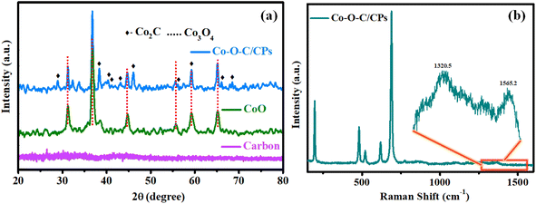
As shown in Scheme 1, the Co–O–C/CPs electrocatalyst was prepared through a two-step process encompassing combustion and calcination. Powder X-ray diffraction XRD analysis was carried out to detect the crystalline phases of the Co–O–C/CPs, CoO, and carbon. Fig. 1a shows the set of Bragg peaks located at 2θ positions of 31.2°, 36.6°, 44.6°, 55.7°, 59.2°, and 65.2° observed for CoO and Co–O–C/CPs, which could be indexed to spinel Co3O4 as per JCPDS Card No. 42-1467.20 The other peaks of Co–O–C/CPs at 2θ positions of 28.8°, 38.2°, 43.5°, 53.9°, and 75.9° were associated with Co2C JCPDS-65-1457.16 In the carbon XRD spectrum, the observed peak at the position of ∼26° and the broadening peak indicated the amorphous state of carbon.21 According to the XRD results, the Co–O–C/CPs and carbon consisted of a high-purity orthorhombic Co2C phase and amorphous state. The low crystallinity of carbon and high crystallinity of Co2C may be responsible for the absence of a carbon diffraction peak in the Co–O–C/CPs. So, the presence of amorphous carbon in the Co–O–C/CPs was characterized using Raman spectroscopy, as described further. The average crystallite sizes of Co–O–C/CPs (21.8 nm) and CoO (10.6 nm) were calculated from the intensity of the respective Bragg peaks using the Scherrer formula (ESI: C2†).To substantiate the XRD results, the formation of Co–O–C/CPs was also confirmed by the Raman signals (Fig. 1b), with four major peaks observed at 480.2, 519, 617.6, and 687.9 cm−1 for Co–O–C/CPs, which were slightly negative-shifted from the standard Co3O4 peaks (484.9, 524.9, 621.9, and 693.2 cm−1) (Fig. S2†).22 The apparent peaks at 480.2 and 687.9 cm−1 might be due to cobalt, since these modes are not reported with carbon-like materials. Another peak was detected at 196.5 cm−1, which might be assigned to a radial breathing mode (RBM) as the carbon wrapper covered cobalt-filled nanoplates. Interestingly, the Co–O–C/CPs also displayed two Raman shifted peaks located at 1320.5 and 1565.2 cm−1 with a significant intensity ratio (ID/IG = 1.09), which were attributed to the disordered D-band and graphitic G-band of carbon, respectively (Fig. S2†).23 The high value of ID/IG of 1.09 confirmed the presence of large defects in Co–O–C/CPs. The above-discussed signals were negatively shifted from that of the standard CoO and carbon, suggesting that there was a strong synergy between cobalt and carbide, which may boost the catalytic activity of the catalyst for water splitting.
3.2 Morphology and size distribution
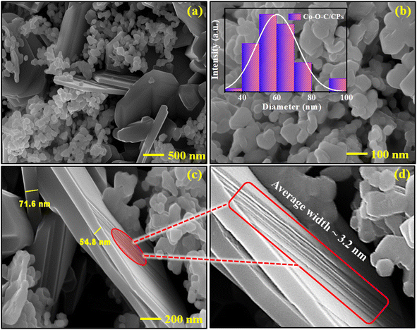
Field emission scanning electron microscopy (FE-SEM) was utilized to measure the morphology and microstructure of the samples. Fig. 2a and b show that the Co–O–C/CPs catalyst exhibited a unique embedded morphology with a mean nanoplates size of ∼60.0 nm. As observed from the high-magnification SEM image, nanosheets with a mean width of ∼78.2 nm were embedded within the nanoplates (Fig. 2c). The enlarged view showed that carbon nanosheets with a mean width of around 3.2 nm were decorated on the surface of the nanoplates (Fig. 2d). The nanosheets-embedded nanoplates could serve as an efficient electrocatalyst, wherein the interconnections between them would facilitate better electron transportation, while the pores between the sheets (clearly visible in the TEM image in Fig. S4a†) would aid in the diffusion of electrolytes during electrocatalysis.24,25 Furthermore, the energy-dispersive X-ray (EDX) pattern exhibited obvious Co, C, and O signals in Co–O–C/CPs, while the elemental mapping also showed the homogenous distribution of the represented elements (Fig. S3†). The above results confirm that pure-phase Co–O–C/CPs with a porous nanosheets-embedded nanoplate structure was successfully fabricated by the combustion process, suggesting the availability and effectiveness of our novel design strategy. The novel self-standing morphology and the potential synergistic effect could favor its electrocatalytic performance.HR-TEM can be utilized to visualize the structure and composition of materials at a very high resolution. The above-mentioned surface properties could be clearly observed in the TEM image (Fig. 3a). The embedded morphology can provide a large specific surface area, which facilitates the catalytic reaction process. Fig. 3b shows a layer of carbon wrapped around the nanoplates, which protects the catalytic metal by forming an overlayer with a precise architecture that can increase the structural stability and prevent the corrosion of Co–O–C/CPs at reaction sites in the catalyst layer and help the catalyst to remain intact and efficient. Without a carbon wrapper, the metal particles may lose contact with the reaction sites, impacting the electrochemical performance. However, at higher magnification, the nanoplates appear to show a core–shell interface, which is a surprising aspect for Co–O–C/CPs electrocatalysts (Fig. 3d and S4b†).26 The interface engineering of Co3O4 and Co2C supported overall water splitting, and the respective mechanism is discussed further. The found interplanar distances of 0.28, 0.11, and 0.14 nm were related to the corresponding (220), (444) planes for Co3O4 and (310) for Co2C, respectively, and the selected area electron diffraction (SAED) pattern rings could be indexed to the (210) plane for Co3O4 and (121) for Co2C, suggesting the successful fabrication of Co–O–C/CPs, with the crystalline nature agreeing well with the XRD results (Fig. 3c, d and S4c†). Moreover, energy-dispersive X-ray spectroscopy (EDX) analysis indicated the existence of Co, O, and C signals only and the absence of other elements, thus confirming the purity of the Co–O–C/CPs (Fig. 3e). Furthermore, the true content of Co (59.3 ± 0.2 wt%) in Co–O–C/CPs was determined by inductively coupled plasma optical emission spectrometry (ICP-OES).
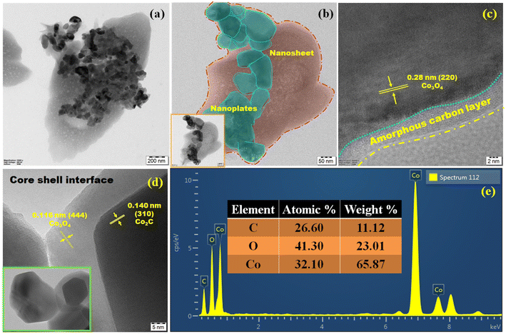 | ||
| Fig. 3 High-resolution transmission electron microscopy (HR-TEM): (a) embedded morphology; (b) embedded view; (c and d) lattice fringes. (e) Energy-dispersive X-ray spectrum. | ||
To analyze the specific surface area and porous structure of Co–O–C/CPs, N2 adsorption/desorption measurements were performed at 77 K, showing a type IV isotherm with an H3 hysteresis loop (observed in the P/P0 range of 0.8–0.95), indicating that Co–O–C/CPs have a mesoporous texture with slit-like pores (Fig. 4a). The specific surface area and pore volume of Co–O–C/CPs were calculated to be 152.55 m2 g−1 and 0.91 cm3 g−1, respectively. In addition, the pore-size distribution curves revealed that the Co–O–C/CPs exhibited typical mesopores (2–60 nm), with the larger pore size and pore volume confirming the presence of uniform pores (20 nm) and a monomodal mesoporosity in Co–O–C/CPs, which are favorable for the exposure of catalytic active sites and for the efficient penetration of electrolytes into active materials to facilitate electrochemical reactions.27
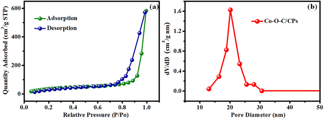 | ||
| Fig. 4 BET surface area analysis. (a) N2 absorption–desorption isotherm plot for Co–O–C/CPs and (b) pore-size distribution. | ||
3.3 Electronic structure and chemical state of Co–O–C/CPs
The elemental composition and surface chemical environment of Co–O–C/CPs were investigated by X-ray photoelectron spectroscopy (XPS), with the survey spectrum showing the existence of Co (22.56%), O (61.13%), and C (16.32%) elements (Fig. 5a). As displayed in Fig. 5b, the peaks centered at 780.4 and 796.0 eV along with the double satellites at 789.2 and 803.6 eV in the Co 2p XPS spectrum could be attributed to Co2+ species in Co–O–C/CPs. Spin–orbital splitting between the Co 2p3/2 and Co 2p1/2 peaks was observed at 15.6 eV. Simultaneously, the peaks observed around 779.4 and 794.6 eV were assigned to Co–C. Based on the XPS and XRD results, we speculated that the Co–C phase originated from the decomposition of Co–O–C/CPs.28 Concerning the C 1s binding energy, four types of peaks could be observed (Fig. 5c); specifically, peaks located at 283.7, 284.4, 285.5, and 288.4 eV, belonging to the characteristic C–Co, C–C, C defect species, and O–C/O![[double bond, length as m-dash]](https://www.rsc.org/images/entities/char_e001.gif) C–O bonds.29 The O 1s spectrum could be deconvoluted into three peaks (Fig. 5d). The first peak (OI) appeared at 529.8 eV, which is commonly seen for oxygen bonded to transition metals, and was assigned to the stoichiometric oxygen in the surface oxide species of Co–O–C/CPs. The other two peaks were located at 530.2 eV (OII) and 532.1 eV (OIII) and were ascribed to oxygen with a lower coordination and the surface oxygen adsorbate, correspondingly, indicating that the surface of the embedded electrocatalyst may contain a lot of defects. Such defects can improve the conductivity of the surface oxide and promote the adsorption of OOHad, which is very important intermediate in the oxygen evolution process.28,30,31
C–O bonds.29 The O 1s spectrum could be deconvoluted into three peaks (Fig. 5d). The first peak (OI) appeared at 529.8 eV, which is commonly seen for oxygen bonded to transition metals, and was assigned to the stoichiometric oxygen in the surface oxide species of Co–O–C/CPs. The other two peaks were located at 530.2 eV (OII) and 532.1 eV (OIII) and were ascribed to oxygen with a lower coordination and the surface oxygen adsorbate, correspondingly, indicating that the surface of the embedded electrocatalyst may contain a lot of defects. Such defects can improve the conductivity of the surface oxide and promote the adsorption of OOHad, which is very important intermediate in the oxygen evolution process.28,30,31
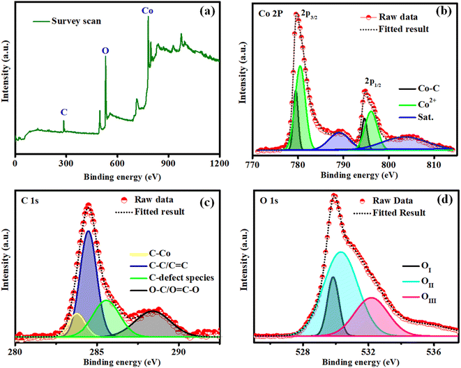 | ||
| Fig. 5 X-ray photoelectron spectra of Co–O–C/CPs: (a) survey scan; (b) cobalt; (c) carbon; (d) oxygen. | ||
3.4 Electrochemical evaluation of Co–O–C/CPs for the HER
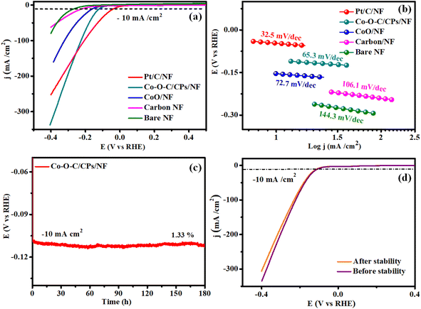
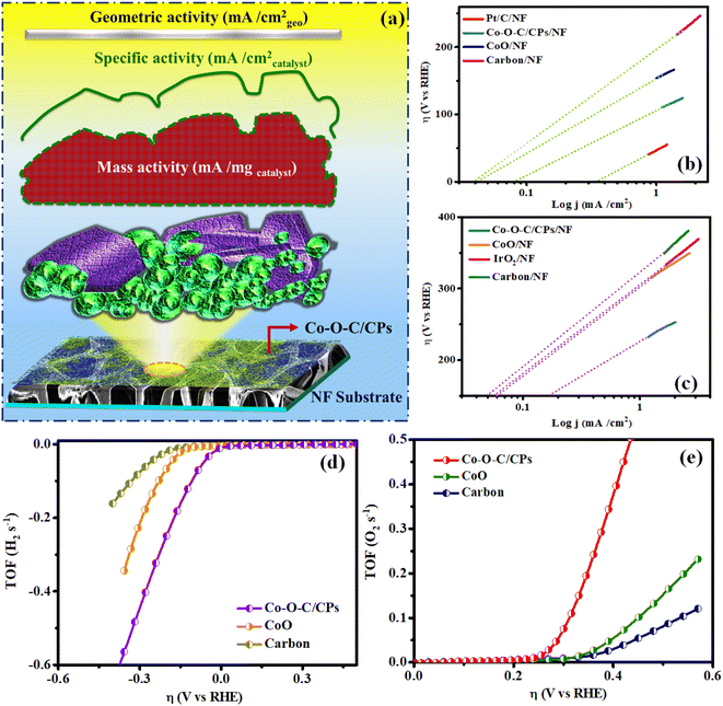
The HER and OER catalytic performances of the Co–O–C/CPs were measured at room temperature in different molar amounts of electrolyte (0.1, 1, 3 M) along with several comparative catalysts, including CoO, carbon, the commercial catalyst IrO2, and bare NF. The 1 M KOH demonstrated high activity for Co–O–C/CPs because of its optimum concentration (Fig. S5†). The polarization curves were collected by linear sweep voltammetry (LSV) at a scan rate of 5 mV s−1. Fig. 6a shows the measured LSV curves of the catalysts without iR correction. Note that the bare NF substrate exhibited inferior catalytic activity, whereas Pt/C on NF (36 mV) demonstrated the highest activity. As displayed in Fig. 6a, the η10 value of Co–O–C/CPs was only 115 mV, while CoO (156 mV), carbon (221 mV), and bare NF (267 mV) showed higher overpotentials, showing that the synergistic effect could improve the electrochemical activity. Compared with other reported carbide-based materials, Co–O–C/CPs exhibited higher activity for the HER (ESI: T3†). Next, the reaction kinetics and pathway information during the HER were obtained through Tafel plots (Fig. 6b). Instead of Pt/C, we also used graphite as a counter electrode to analyze the catalytic activity due to its unique properties. Graphite and Pt/C are commonly used as counter electrodes in electrochemical systems, each offering distinct advantages. Graphite is cost-effective, chemically stable, and possesses good electrical conductivity, making it an attractive option for large-scale or low-cost applications. Its inertness also reduces the risk of unwanted side reactions during electrochemical processes. However, graphite's electrocatalytic activity is generally lower compared to platinum-based materials, which may limit its effectiveness in certain applications requiring high catalytic performance. The counter electrode graphite tip (0.7 mm) and rod (2 mm) exhibited catalytic activities of 167 and 148 mV for the Co–O–C/CPs, respectively, which were lower compared to the activity and Tafel value observed with Pt/C (Fig. S6 and Movie S2†). Even the graphite tip and rod electrodes showed activity lagging behind Pt/C due to the size of the electrodes. Finally, platinum is preferable for high-precision or demanding applications due to its superior properties, whereas graphite is a good choice for more routine or cost-sensitive experiments, provided its limitations are taken into account. The Tafel slope of Co–O–C/CPs was measured to be 65.3 mV dec−1, which was larger than that of Pt/C on NF (32.5 mV dec−1) but smaller than the value of CoO/NF (72.7 mV dec−1), carbon (106.1 mV dec−1), and bare NF (144.3 mV dec−1), indicating the faster kinetics induced by the synergistic effect. The Tafel slope value for Co–O–C/CPs suggests that the HER proceeded through the Volmer–Heyrovsky mechanism, i.e., the initially formed adsorbed hydrogen atom (Hads) accepts an electron and then combines with a water molecule to discharge as H2.32 Similarly, a stability test was conducted to further explore the durability, which displayed negligible attenuation in an HER testing period of 180 h (Fig. 6c). According to the LSV curve recorded after 180 h stability test in 1 M KOH, there was no noticeable variation in the current density compared with before the stability test (Fig. 6d).Similarly, the OER performances of the electrocatalysts, including Co–O–C/CPs, CoO, carbon, commercial IrO2, and NF, were explored using the same three-electrode device in 1 M KOH. As depicted in Fig. 7a, CoO, carbon, and bare NF showed limited catalytic activity, demanding large overpotentials of 325, 351, and 362 mV to deliver a current density of 10 mA cm−2. Importantly, by the combustion followed by calcination method, the embedding morphology enhanced the catalytic performance and obeyed the corresponding OER mechanism:
| OH + * → *OH + e− |
| OH* + OH → *O + H2O + e− |
| O* + OH → *OOH + e− |
| OOH* + OH → O2 + *H2O + e−, * − active sites |
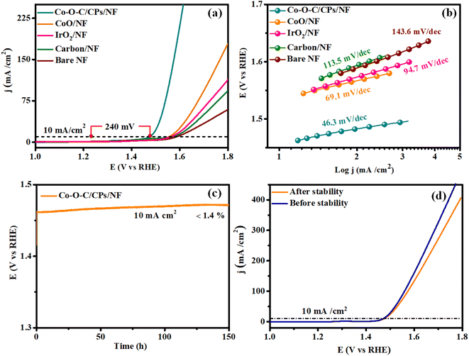
In detail, Co–O–C/CPs showed the best OER catalytic activity with an exceedingly low overpotential of 240 mV to afford 10 mA cm−2, which was lower than for the commercial IrO2 (338 mV). These results indicate that constructing an embedded morphology can effectively promote the performance during OER catalysis.33,34 Notably, the OER activity of Co–O–C/CPs was superior to other reported carbide-based OER electrocatalysts in alkaline media (ESI: T2†). To study the OER reaction kinetics, we extracted the Tafel plots from the measured LSV curves to calculate the corresponding Tafel slopes. The Tafel slope for Co–O–C/CPs was determined to be 46.3 mV dec−1, much smaller than that of CoO (69.1 mV dec−1), IrO2 (94.7 mV dec−1), carbon (113.5 mV dec−1), and bare NF (143.6 mV dec−1), demonstrating its best OER kinetics (Fig. 7b). Apart from the catalytic activity, long-term durability is another essential quality for OER electrocatalysts. The durability of Co–O–C/CPs was shown by the retained excellent OER activity during extended operation, with negligible degradation in current density detected over a testing period of 150 h (Fig. 7c). After the stability test, the LSV curve showed a negligible loss compared with the initial one. The results illustrate the robust durability of Co–O–C/CPs during the water oxidation process in an alkaline electrolyte (Fig. 7d).
3.5 Electrochemical active surface area and electrochemical impedance spectroscopy analysis of the Co–O–C/CPs
Moreover, double-layer capacitance (Cdl) measurements and electrochemical impedance spectroscopy (EIS) were employed to evaluate the electrochemical surface area (ECSA) and electron conductivity. The electrochemical surface area (ECSA) analysis is one of the most common methods for determining the number of catalytic active sites in Co–O–C/CPs electrocatalysts (Fig. S7†).35,36 To further illuminate the intrinsic activity for electrocatalytic water splitting, the electrochemical surface area (ECSA) of the electrocatalyst was estimated from cyclic voltammetry (CV) curves in a region without electrochemical reactions. This was done by measuring the electrochemical double-layer capacitance (Cdl) in 1.0 M KOH solution. Based on the CV curves recorded at different scan rates (40–140 mV s−1), a linear relationship between the scan rate and current density was obtained, whose line slope (equivalent to twice the Cdl) can be reflected in the ECSA, since the ECSA of the electrocatalyst is proportional to the Cdl value. The double-layer capacitance of Co–O–C/CPs (58.3 mF cm−2) was larger than that of CoO (28.8 mF cm−2), carbon (6.2 mF cm−2), and bare NF (3.31 mF cm−2), suggesting that the Co–O–C/CPs possessed more active sites for the electrolyte, which favors improving the electrocatalytic performance (Fig. 8a and ESI: C4†). Additionally, electrochemical impedance spectroscopy (EIS) was carried out to further examine the kinetics and the electron-transport capability.17 The Nyquist plots in Fig. 8b reveal that the charge-transfer resistance (Rct) of Co–O–C/CPs (2.87 Ω) was lower than that of CoO (4.41 Ω), carbon (6.9 Ω), and bare NF (7.83 Ω), indicating a great improvement in the kinetics and charge transfer on the Co–O–C/CPs catalyst. These findings were in good agreement with the trends observed for the high catalytic activity, providing an intrinsic reason for the superior OER and HER performances (Fig. 8b).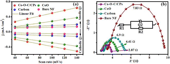 | ||
| Fig. 8 (a) Double-layer capacitance (Cdl) of Co–O–C/CPs, CoO, carbon and bare NF and (b) their electrochemical impedance spectra (inset: Randel's circuit). | ||
3.6 Intrinsic activity properties of the Co–O–C/CPs
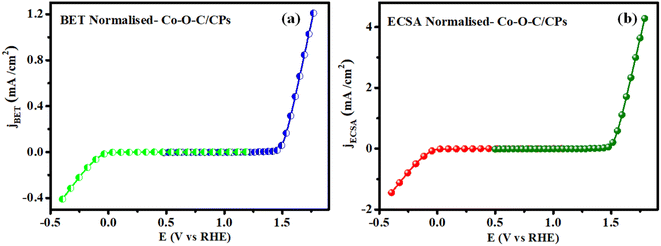
To evaluate the intrinsic activity, it is necessary to normalize the OER and HER kinetics currents to the real surface area of the catalyst. Previously, the BET surface area was used to normalize the activity and was referred to as the specific activity (jBET) (Fig. 11a). However, jBET normalization is important as it can reveal the available surface area of the Co–O–C/CPs, with the measurements made based on N2 adsorption and desorption. Moreover, the ECSA is another important parameter that can reflect the real surface area of a material (jECSA) that is truly exposed to the electrolyte, unlike the geometrical surface area (Fig. 11b). The ECSA-normalized activity can thus provide a valid assessment of the catalytic features of the Co–O–C/CPs. The activity normalized jECSA was somewhat greater than jBET, indicating that the ECSA was measured from a wetted electrolyte. The jBET and jECSA are promising activity parameters that can reflect the intrinsic catalytic properties of the Co–O–C/CPs. Moreover, there can exist huge differences in the measured jBET and jECSA of the same material because of geometrical considerations, the distribution of active sites, or electronic interactions.
3.7 Overall and solar cell water splitting with the Co–O–C/CPs
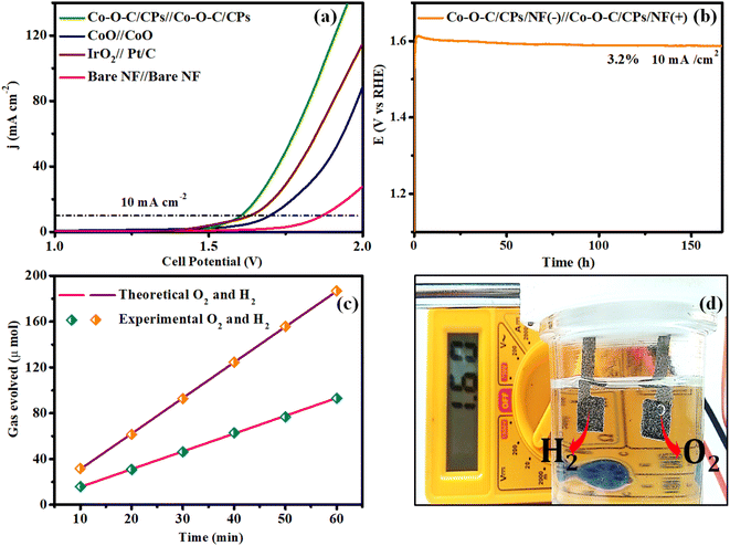
Encouraged by the excellent electrocatalytic activity of Co–O–C/CPs toward both the OER and HER, the overall water splitting performance was further studied using a two-electrode alkaline electrolyzer.40,41 The water electrolysis performed with Co–O–C/CPs‖Co–O–C/CPs required a lower cell voltage of 1.60 V to achieve a current density of 10 mA cm−2 compared to IrO2‖Pt/C (1.63 V), CoO‖CoO (1.69 V) and other reported catalysts, indicating the crucial role of constructing embedded Co–O–C/CPs for improving the activity and the promising durability, whereby constant electrolysis could be sustained at 10 mA cm−2 for up to 170 h with negligible degradation (Fig. 12a, b and ESI: T3†). The quantities of hydrogen and oxygen gases produced by Co–O–C/CPs were also measured using gas chromatography and the faradaic efficiency (FE) method (ESI: C6†).42 The measured amounts showed an almost 89% FE, matching with the theoretical prediction (Fig. 12c). Solar energy is the most abundant natural renewable resource and can be utilized to increase hydrogen production.18,20 To assess the practicality for real-world applications, additional validation was conducted using a commercial solar cell, as depicted in Fig. S9.† The highest voltage of 5.83 V was obtained with the traditional solar panel because of its greater open circuit voltage (OCV) and current density. The solar panel anode and cathode were directly linked to the solar cell arrangement, while a copper pin was utilized to connect the voltmeter. The Co–O–C/CPs generated hydrogen and oxygen gas while splitting water at 1.60 V, as measured by a multimeter (Fig. 12d and Movie S3†). During water electrolysis, approximately 4.13 mmol h−1 cm−2 of hydrogen was released (ESI: C7†). These results clearly show that the Co–O–C/CPs catalyst has significant potential for use in large-scale water electrolysis applications.3.8 Post analysis of Co–O–C/CPs
After the electrochemical stability test, we characterized the morphology and chemical composition of Co–O–C/CPs by FE-SEM, along with elemental mapping, XRD, and XPS. The FE-SEM images show the embedded morphology of Co–O–C/CPs was well maintained.43–45 The electrochemical etching in Co–O–C/CPs caused the particles to be diminished due to the continuous evolution of hydrogen and oxygen bubbles, which caused surface imperfections and the equal distribution of constituent elements, as shown in SEM-EDX mapping (Fig. S10 and S11†). The XRD patterns also demonstrated that the crystalline Co–O–C/CPs had transitioned to an amorphous phase, with visible nickel diffraction peaks (Fig. S12†). The collapsing order of the catalyst (Co–O–C/CPs), which facilitates faster electron transport with rapid electrochemical kinetics diffusion and surface amorphization may improve the electrochemical activity.36,46 After the OER and HER treatment, there were modest changes in the locations and intensities of the fitting peaks for Co, C, and O in the XPS spectra (Fig. S13–S15†). The spectra showed the shift to higher binding energies, indicating the formation of CoOOH species, oxidized to form new C–O bonds. The possible reduction in binding energy suggested reduced cobalt species or changes in the oxidation state, which might suggest hydrogenation or reduction processes affecting the carbon matrix. These changes indicate that the Co–O–C/CPs play an active role in catalytic reactions and in the resilience of the electrode surface for maintaining structural integrity. Understanding these changes provides valuable insights into the design and optimization of Co–O–C/CPs as more efficient and durable electrocatalysts for water splitting applications.4 Pre-conclusion
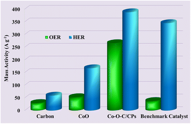
Based on the preceding investigation, the high performance of the Co–O–C/CPs catalyst may be attributed to the following aspects: (1) the successful synthesis of the Co–O–C/CPs catalyst by a solvent-free combustion process, which is also a green method. This novel methodology requires less energy to reduce the environmental burden of catalyst preparation; (2) the embedded morphology of the Co–O–C/CPs, which can accelerate electron transport, ensuring abundant active sites; (3) it obeys both the HER and OER with high catalytic activity and stability for long-term use with minimal degradation, while the ECSA and TOF calculations reveal that the Co–O–C/CPs structure is beneficial for exposing more active sites, and thus, it exhibits excellent intrinsic activity; (4) the lower resistivity, as proved by the EIS analysis, which enhance the OER and HER kinetics of the Co–O–C/CPs; (5) after stability testing, shifts in the binding energies of Co (oxo)hydroxide species and the deposition of an amorphous layer were observed, indicating the formation of the actual active sites during the OER and HER processes; and finally (6) application for solar cell water splitting required a 1.60 V cell potential to split oxygen and hydrogen with 89% efficiency.5 Conclusion
In summary, a novel Co–O–C/CPs electrocatalyst was designed through a two-step strategy involving solvent-free combustion and calcination. The characteristic of adsorbing Co2C on the core and Co3O4 on the shell led to abundant active sites, excellent intrinsic activity, and favorable kinetics for the catalyst. Consequently, the Co–O–C/CPs exhibited higher OER and HER performance, featuring low overpotentials (240 mV for the OER; 115 mV for the HER) and Tafel slopes (46.3 mV dec−1 for the OER; 65.3 mV dec−1 for the HER). Likewise, an alkaline electrolyzer built with the bifunctional Co–O–C/CPs electrocatalyst demonstrated excellent overall water-splitting efficiency (1.60 V@10 mA cm−2). Furthermore, a solar cell-driven alkaline electrolyzer (Co–O–C/CPs‖Co–O–C/CPs-1.60 V) was assembled and demonstrated the possibility for practical applications. Thus, the suggested technique offers fresh insights into developing an extremely effective metal carbide-based electrocatalyst for water electrolysis by adsorbing transition metal atoms on the surface of the electrocatalyst. After electrochemical treatment of Co–O–C/CPs, the core of cobalt carbide can undergo oxidation forming cobalt hydroxides or oxyhydroxide, which are often more active for oxygen evolution than the original carbide surface. Unlike the OER, typically the HER does not cause a significant oxidation of cobalt carbide or adsorb hydrogen species, potentially enhancing the catalytic activity. Ensuring a clean and active surface is crucial for maintaining higher electrochemical performance. We believe that the enlarged active surface area and intrinsic activity are the primary origins of the improved OER and HER activity.6 Environmental assessment of the solvent-free synthesis strategy
The proposed method involving solvent-free mechanochemical treatment followed by combustion is considered a green chemistry approach for synthesizing nanomaterials, with significant benefits in terms of environmental impact, cost, efficiency, and safety. Mechanochemical methods offer simplicity and an ability to produce unique phases, while combustion methods are notable for their rapid, high-temperature reactions and high purity outputs. These attributes make them attractive alternatives to traditional solvent-based synthesis methods in various fields of materials science. Some of the benefits of solvent-free syntheses are mentioned below.6.1 Resource utilization
The solvent-free mechanochemical approach avoids the use of hazardous solvents, which significantly reduces the environmental burden associated with their production. It also requires less energy compared to conventional thermal methods, as it can often operate at ambient temperature and pressure.6.2 Green synthesis and production
The mechanochemical method is a greener synthesis method that can reduce solvent use and waste.6.3 Emissions and waste
The mechanochemical method has lower energy consumption, which translates to reduced greenhouse gas emissions, particularly if renewable energy sources are used to power the mechanochemical equipment. There is also less solid waste produced compared to traditional methods that require extensive purification steps involving solvents.6.4 Usage phase
Cobalt carbide electrocatalysts are often used in energy conversion and storage applications, such as in fuel cells and electrolyzers, which can support renewable energy systems and reduce the reliance on fossil fuels. High efficiency and stability can lead to longer lifespans for devices, reducing the need for frequent replacements and associated waste.Data availability
Data will be made available upon request.Conflicts of interest
The author declares that they have no known competing financial interests or personal relationships that could have appeared to influence the work reported in this paper.Acknowledgements
This research was supported by the DST (EMR/2014/000094, F. No. SR/S1/1C-73/2010, F. No. SR/S1/1C-07/2007), DRDO (213/MAT/10-11), CSIR (No. 01/(2707)/13EMR-II), UGC (6-21/2008, F. No. 30-71/2004 (SR): No. F.19-248/2020 (BSR)), DST-Nano Mission (SR/NM/NS-1001/2016), TANSCST (S. No. TNSCST/STP/PRG/03/2019-2020/3626), TANSCHE-MRP (RGB/2019-20/AMU/HECP-0064).References
- L. Han, S. Dong and E. Wang, Adv. Mater., 2016, 28, 9266–9291 CrossRef CAS.
- B. Eftekharinia, H. Pezeshki and A. Dabirian, ACS Appl. Mater. Interfaces, 2020, 12, 17424–17435 CrossRef CAS PubMed.
- H. H. Mohamed, in Sustainable Materials and Green Processing for Energy Conversion, Elsevier, 2022, pp. 169–212 Search PubMed.
- A. M. Asiri, D. Ren, H. Zhang, S. Bahadar Khan, K. A. Alamry, H. M. Marwani, M. Sherjeel Javed Khan, W. A. Adeosun, S. M. Zakeeruddin and M. Grätzel, ChemSusChem, 2022, 15, e202102471 CrossRef CAS.
- C. Wei, R. R. Rao, J. Peng, B. Huang, I. E. Stephens, M. Risch, Z. J. Xu and Y. Shao-Horn, Adv. Mater., 2019, 31, 1806296 CrossRef PubMed.
- S. Farhadi and M. Zaidi, J. Mol. Catal. A, 2009, 299, 18–25 CrossRef CAS.
- F. Saito, Q. Zhang and J. Kano, J. Mater. Sci., 2004, 39, 5051–5055 CrossRef CAS.
- M. Sangamithirai, S. Mathi, V. Ashok and J. Jayabharathi, ChemistrySelect, 2023, 8, 202300102 CrossRef.
- H. B. Jin, M. S. Cao, Y. X. Chen, J. T. Li and S. Agathopoulos, Ceram. Int., 2008, 34, 1267–1271 CrossRef CAS.
- S. A. Hassanzadeh-Tabrizi, D. Davoodi, A. A. Beykzadeh and A. Chami, Int. J. Refract. Met. Hard Mater., 2015, 51, 1–5 CrossRef CAS.
- H. T. Chung, J. H. Won and P. Zelenay, Nat. Commun., 2013, 4, 1922 CrossRef PubMed.
- J. Cheng and D. Wang, Chin. J. Catal., 2022, 43, 1380–1398 CrossRef CAS.
- M. Vijayarangan, A. Gayathri, V. Ashok, M. Sangamithirai, J. Jayabharathi and V. Thanikachalam, Energy Fuels, 2024, 38, 1364–1372 CrossRef CAS.
- A. K. Tareen, G. S. Priyanga, K. Khan, E. Pervaiz, T. Thomas and M. Yang, ChemSusChem, 2019, 12, 3941–3954 CrossRef CAS PubMed.
- H. Wang, S. Zhu, J. Deng, W. Zhang, Y. Feng and J. Ma, Chin. Chem. Lett., 2021, 32, 291–298 CrossRef CAS.
- D. Zha, R. Wang, S. Tian, Z. J. Jiang, Z. Xu, C. Qin, X. Tian and Z. Jiang, Nanomicro Lett., 2024, 16, 250–266 CAS.
- P. Wang, J. Zhu, Z. Pu, R. Qin, C. Zhang, D. Chen, Q. Liu, D. Wu, W. Li, S. Liu and J. Xiao, J. Appl. Catal. B, 2021, 296, 120334 CrossRef CAS.
- J. Jiang, Q. Liu, C. Zeng and L. Ai, J. Mater. Chem. A, 2017, 5, 16929–16935 RSC.
- J. Chen, B. Ren, H. Cui and C. Wang, Small, 2020, 16, 1907556 CrossRef CAS.
- M. Sangamithirai, M. Vijayarangan, A. Gayathri, M. Muthamildevi and J. Jayabharathi, J. Sustainable Energy Fuels, 2024, 8, 3124–3135 RSC.
- F. Astuti, N. Sari, V. L. Maghfirohtuzzoimah, R. Asih, M. A. Baqiya and D. Darminto, J. Fis. dan Apl., 2020, 16, 91–94 CrossRef.
- S. A. Rasaki, H. Shen, T. Thomas and M. Yang, ACS Appl. Nano Mater., 2019, 2, 3662–3670 CrossRef CAS.
- M. Sevilla, C. Sanchís, T. Valdés-Solís, E. Morallón and A. B. Fuertes, J. Phys. Chem. C, 2007, 111, 9749–9756 CrossRef CAS.
- M. Vijayarangan, S. Mathi, A. Gayathri, J. Jayabarathi and V. Thanikachalam, ChemistrySelect, 2022, 7, 202203206 CrossRef.
- Y. Zhang, W. Ye, J. Fan, V. Cecen, P. Shi, Y. Min and Q. Xu, ACS Sustainable Chem. Eng., 2021, 9, 11052–11061 CrossRef CAS.
- H. H. Zhang, Y. B. Ren, Z. L. Yuan, N. X. Kang, S. Mehdi, C. C. Xing, X. Y. Liu, Y. P. Fan, B. J. Li and B. Z. Liu, Rare Met., 2023, 42, 1935–1945 CrossRef CAS.
- M. Pudukudy and Z. Yaakob, J. Clust. Sci., 2015, 26, 1187–1201 CrossRef CAS.
- X. Yuan, X. Wang, M. S. Riaz, C. Dong, Z. Zhang and F. Huang, Catal. Sci. Technol., 2018, 8, 2427–2433 RSC.
- Y. Wu, Z. Xiao, Z. Jin, X. Li and Y. Chen, J. Colloid Interface Sci., 2021, 590, 321–329 CrossRef CAS PubMed.
- M. Sangamithirai, V. Ashok, A. Gayathri, M. Vijayarangan and J. Jayabharathi, New J. Chem., 2024, 48, 7070–7080 RSC.
- B. Zhang, Z. Jiang, X. Shang, S. Li and Z. J. Jiang, J. Mater. Chem. A, 2021, 9, 25934–25943 RSC.
- R. S. Alkhaldi, M. A. Gondal, M. J. S. Mohamed, M. A. Almessiere, A. Baykal, S. Caliskan and Y. Slimani, ACS Appl. Nano Mater., 2024, 7, 2867–2878 CrossRef CAS.
- T. Wang, Q. Pang, B. Li, Y. Chen and J. Z. Zhang, Appl. Phys. Lett., 2021, 118, 233903 CrossRef CAS.
- T. Munawar, A. Bashir, A. El-Marghany, L. Shen, Z. Tu, S. Fatima, A. G. Abid, S. A. Khan, M. Koc, C. F. Yan and F. Iqbal, Fuel, 2024, 375, 132445 CrossRef CAS.
- D. Lai, Q. Kang, F. Gao and Q. Lu, J. Mater. Chem. A, 2021, 9, 17913–17922 RSC.
- M. Vijayarangan, M. Sangamithirai, V. Ashok, K. Umapathy, J. Jayabharathi and V. Thanikachalam, ACS Appl. Mater. Interface., 2024, 16, 35013–35023 CrossRef CAS PubMed.
- A. Ali, F. Long and P. K. Shen, Electrochem. Energy Rev., 2022, 5, 1–30 CrossRef CAS.
- S. Wang, A. Lu and C. J. Zhong, Nano Converg., 2021, 8, 4–27 CrossRef CAS PubMed.
- S. Anantharaj and S. Kundu, ACS Energy Lett., 2019, 4, 1260–1264 CrossRef CAS.
- X. P. Li, C. Huang, W. K. Han, T. Ouyang and Z. Q. Liu, Chin. Chem. Lett., 2021, 32, 2597–2616 CrossRef CAS.
- J. Li, G. Wei, Y. Zhu, Y. Xi, X. Pan, Y. Ji, I. V. Zatovsky and W. Han, J. Mater. Chem. A, 2017, 5, 14828–14837 RSC.
- Y. Li, J. Chen, P. Cai and Z. Wen, J. Mater. Chem. A, 2018, 6, 4948–4954 RSC.
- G. Cavigiolio, B. Shao, E. G. Geier, G. Ren, J. W. Heinecke and M. N. Oda, Biochem., 2008, 47, 4770–4779 CrossRef CAS PubMed.
- Q. Zia, R. Androsch, H. J. Radusch and S. Piccarolo, Polym., 2006, 47, 8163–8172 CrossRef CAS.
- B. Deng, L. Zhou, Z. Jiang and Z. J. Jiang, J. Catal., 2019, 373, 81–92 CrossRef CAS.
- D. Guan, W. Zhou and Z. Shao, Small Sci., 2021, 1, 2100030 CrossRef CAS.
Footnote |
| † Electronic supplementary information (ESI) available: Experimental section, instrument details used for characterization (FE-SEM, EDS with elemental mapping, HR-TEM, XRD, FTIR and XPS) electrode preparation and electrochemical characterization, ECSA, post analysis using FE-SEM, EDS-elemental mapping, XRD and XPS. Solar cell to hydrogen production, calculation of RHE conversion, Tafel equation, turn over frequency, energy calculation, ECSA calculations, faradaic efficiency, hydrogen generation, comparison table of reported electrocatalyst. The synthetic process of Co–O–C/CPs (release of Co2) and continuous evolution of H2 (cathode) and O2 (anode) bubbles using a solar panel-assisted water-splitting device under sunlight (MP4). See DOI: https://doi.org/10.1039/d4se01320d |
| This journal is © The Royal Society of Chemistry 2025 |


