 Open Access Article
A gap-designed photo-reactor for high-performance photothermal methane reforming†
Hamada A.
El-Naggar
,
Hisao
Yoshida
 and
Akira
Yamamoto
 *
*
Graduate School of Human and Environmental Studies, Kyoto University, Yoshida Nihonmatsu-cho, Sakyo-ku, Kyoto 606-8501, Japan. E-mail: yamamoto.akira.2a@kyoto-u.ac.jp; Fax: +81-75-753-2988; Tel: +81-75-753-6882
First published on 13th February 2025
Abstract
Photothermal catalysis has garnered significant attention as a potential solution to address energy scarcity. In photothermal catalysis, light irradiation directly heats the catalyst bed, inducing a localized temperature gradient. However, in methane reforming reactions such as dry reforming, the undesired reverse reaction typically proceeds in the lower temperature zone of the catalyst bed, which reduces the overall efficiency. To address this issue, we developed a novel flow-type photo-reactor composed of a quartz tube and a quartz filler welded within the tube. The narrow catalyst-filled gap was used for catalytic reaction that minimizes the temperature gradient under light irradiation. The developed reactor, termed the gap reactor, demonstrated excellent catalytic performance in photothermal dry reforming of methane (PT-DRM), achieving ∼70–80% conversion of CH4 and CO2 over 100 hours using a SiO2-encapsulated Co–Ni alloy catalyst previously developed by our group. Compared to the conventional quartz tube reactor with the same cross-sectional area for light absorption, the gap reactor significantly enhanced both conversion and stability. Furthermore, integrating the gap reactor with steam addition to the reaction feed successfully suppressed coke formation to only 0.6 wt% after approximately 50 hours of reaction. This study highlights the benefits of the gap reactor design in high-temperature catalytic applications up to 1000 °C.
1. Introduction
Greenhouse gases (GHGs), particularly methane (CH4) and carbon dioxide (CO2), are recognized as major contributors to climate change, urging approaches to reduce their emissions. Dry reforming of methane (DRM, eqn (1)) is proposed to reduce both CO2 and CH4 emissions in an energy-intensive reaction to produce syngas. However, the highly endothermic nature of DRM and low catalyst stability present challenges. Due to the thermodynamic limitation, high CH4 conversion could be obtained at high temperatures over 800 °C, where the temperature could be achieved by combustion of fossil fuel, similar to an industrial steam-reforming process, when constructing a large-scale process.1,2 This dependence on fossil fuels offsets the advantages of DRM by increasing the carbon footprint of this reaction.3 Hence, solar-induced photothermal effect was proposed to drive this reaction without the combustion of fossil fuels.4–8| CH4 + CO2 ⇄ 2H2 + 2CO, ΔH° = 247 kJ mol−1 | (1) |
Photothermal catalysis has received significant attention due to global energy concerns. The photothermal effect can induce sufficiently high temperatures ranging from 800 to 1500 °C.9–11 Therefore, photothermally-driven dry reforming of methane (PT-DRM) was proposed to achieve considerable CH4 conversion.4,12–14 However, a temperature gradient, caused by non-uniform light distribution under focused light, poses key challenges in photothermal catalysis.4,11,15,16 This temperature gradient promotes the reverse reactions in the low-temperature zone of the catalyst bed.15 Several recent studies have investigated reaction systems that combine external heating with photothermal catalysis,12,17–19 these systems are likely to achieve more uniform temperature distributions. However, achieving stable and high CH4 conversion in the PT-DRM reaction without external heating is still challenging. This raises the need for thorough studies to develop stable catalysts and optimum reactor design to maximize the CH4 conversion under high irradiation fluxes.4,20,21
Temperature gradients not only decrease the conversion efficiency, but also severely compromise the catalyst stability. Although high temperatures would benefit the reaction rate and conversion in PT-DRM, they can cause significant sintering of catalytically-active metal nanoparticles.22–25 In addition, catalysts in the low-temperature zone promote coke deposition due to the thermodynamic preference15via side reactions such as CH4 decomposition (eqn (2)) and Boudouard reaction (eqn (3)).
| CH4 ⇄ 2H2 + C(s), ΔH° = 75 kJ mol−1 | (2) |
| 2CO ⇄ CO2 + C(s), ΔH° = −172 kJ mol−1 | (3) |
Therefore, it is crucial to develop stable catalysts with high resistances to sintering and coke deposition. We previously reported that Co–Ni alloy nanoparticles encapsulated in porous SiO2 yolk shell (Co–Ni@SiO2) exhibited improved activity and enhanced stability for the PT-DRM reaction, compared to the monometallic Ni@SiO2 catalyst or impregnation catalyst without a SiO2 shell.15
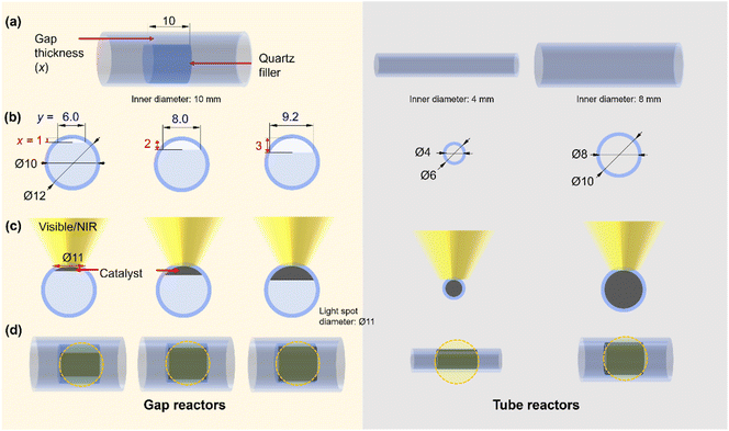
From the reactor design perspective, several studies have proposed new designs of photo-reactors.5,20,21 For example, a double-tube type photo-reactor with vacuum thermal insulation and a selective solar absorbing coating was employed to achieve high temperature for CO2 methanation under light irradiation.26 Additionally, a reflective multi-pass photoreactor composed of a tube reactor and solar concentrator was also reported as a low-cost and highly effective photoreactor without the need for sun tracking for application under irradiation conditions.20 These examples highlight the importance of reactor design from both fundamental and application-oriented perspectives. Inspired by these studies, we hypothesized that minimizing the temperature gradient has the potential to enhance the performance of the photothermal CH4 reforming reaction under high-temperature conditions. Herein, we developed a novel flow-type photo-reactor consisting of a quartz tube and a quartz filler welded inside the tube, with the catalyst positioned in the gap between them (referred to hereafter as the “gap reactor”, Fig. 1a). The decrease in the thickness of the catalyst layer could contribute to a decrease in the temperature gradient. The developed gap-reactor provided superior performance in CH4 conversion through dry- and bi-reforming reactions using the Co–Ni@SiO2 catalyst.
2. Experimental
2.1 Catalyst preparation
Co–Ni alloy nanoparticles encapsulated within a porous SiO2 yolk shell were prepared by a two-step method according to a previous report15 with slight modification. First, Co5Ni95 hydroxide nanoplatelets were prepared by hydrothermal treatment, and then encapsulated within a SiO2 shell. Briefly, a solution of pre-dissolved polyvinylpyrrolidone (PVP, 3 g) in deionized water (DIW, 120 mL) was mixed with 0.3 mmol of Co(NO3)2·6H2O and 5.7 mmol of Ni(NO3)2·6H2O solutions under Ar flow. After stirring for half an hour, 30 mL of NaOH was added dropwise over 30 minutes. After that, the mixture solution was transferred to an autoclave lined with Teflon to be hydrothermally treated at 150 °C for six hours. The resulting slurry was decanted three times with DIW after it had cooled to room temperature.After dispersing the Co5Ni95 nanoplatelet suspension (150 mL), 300 mL of ethanol and 15 mL of NH3(aq) were added. Separately, cetyltrimethylammonium bromide (CTAB, 2.7 g) was dissolved in ethanol/DIW (40 mL, 1/1, vol%). Then, 15.5 mL of tetraethyl orthosilicate (TEOS) and the CTAB solution were simultaneously added dropwise to the nanoplatelet suspension. After vigorously stirring the mixture for one hour, it settled down. After the 250 mL supernatant was decanted, the 200 mL suspension was dried at 80 °C using a water bath and then kept in an oven overnight at 80 °C to remove any remaining solvents. The catalyst was calcined at 500 °C at the heating rate of 10 °C min−1.
2.2 Reactor design
A flow-type photo-reactor was designed to increase the catalyst temperature for PT-DRM effectively and minimize the temperature gradient. In this reactor, quartz fillers were welded inside quartz tube reactors with an inner diameter of 10 mm, respectively (Fig. 1, for reactor's photograph please see Fig. S1†). In the flat-type quartz reactors used in our previous study,15 controlling the thickness of the catalyst bed and light irradiation area was limited by its manufacturing process. The advantage of this gap reactor lies in its ability to regulate the catalyst space through the shape of the internal filler. In this study, three reactors with gap thicknesses of 1, 2, and 3 mm were used for catalyst filling and are referred to as x-mm-gap reactors, where x is the gap thickness. Note that, in these reactors, the cross-sectional area of the catalyst exposed to light (Fig. S2†) changes with variations in the gap thickness (Fig. 1). Moreover, the light penetration depth of the thin pellet of the reduced catalyst was <200 μm, indicating that only a limited zone at the top of the catalyst granules is directly heated by light irradiation. For the control experiments, quartz tube reactors with inner diameters of 4 and 8 mm (Fig. 1) were used, where the cross-sectional area in the 2-mm-gap reactor matchs that of the 8-mm-tube reactor. The structural information for the reactors used in this study is summarized in Table 1.| Reactor | Catalyst bed volume/mL | Catalyst bed length/mm | Catalyst weight/mg | GHWVa/L g−1 h−1 |
|---|---|---|---|---|
| a Gas hourly weight velocity. The total flow rate was 200 ml min−1. | ||||
| 1-mm-gap | 0.04 | 10 | 35 | 3.4 × 10² |
| 2-mm-gap | 0.11 | 10 | 60 | 2.0 × 10² |
| 3-mm-gap | 0.20 | 10 | 110 | 1.1 × 10² |
| 4-mm tube | 0.13 | 10 | 60 | 2.0 × 10² |
| 8-mm tube | 0.50 | 10 | 340 | 3.5 × 101 |
2.3 Characterization
The specific surface area was estimated from the amount of N2 adsorption at 77 K using a BEL-MAX-G instrument (MicrotracBEL, Japan), and the porosity of the catalysts was assessed via the Barrett–Joyner–Halenda (BJH) method. X-ray diffraction (XRD) measurement was carried out at room temperature using a Shimadzu LabX XRD-6000 with Cu Kα radiation (40 kV, 30 mA). The crystallite size was determined by the Scherrer equation using the full width at half maxima (FWHM) of the diffraction line at 2θ = 44.8°. Transmission electron microscopy (TEM) was conducted using a JEM-2200SF and JEM-ARM200F devices (JEOL, Japan). UV-visible diffuse reflectance spectra (DRS) were recorded on a JASCO V-570 spectrophotometer with a BaSO4 reference. The amount of deposited coke after the PT-DRM reaction test was determined using the elemental analysis with a CNH analyzer (MT-5 and MT-6, Yanaco Analytical Systems, Japan) and a Micro analyzer (JM-10 and JM-11, J Science Lab, Japan).2.4 Catalytic activity tests
Photothermal and thermal catalytic activity tests were carried out under ambient pressure using a fixed-bed continuous-flow system. The powder of the Co5Ni95@SiO2 catalyst was ground into 150–300 μm granules after pelletization at 40 MPa. The reactors with 1, 2, and 3-mm gap thicknesses were packed with 35, 60, and 110 mg of the granules, respectively (Table 1). The tubular reactors with inner diameters of 4 and 8 mm were filled with 60 mg and 340 mg of the catalyst granules, respectively.Before the activity test, the catalyst was pre-treated in a 100% O2 gas flow (5 mL min−1) at 450 °C for 30 minutes to remove organics, and then reduced for 30 minutes at 600 °C using a 10% H2/Ar gas (100 mL min−1), followed by cooling to room temperature under an Ar flow. In the PT-DRM and PT-BRM reactions, gas compositions were CH4 (22.5 mL min−1)/CO2 (22.5 mL min−1)/N2 (10 mL min−1)/Ar (145 mL min−1) and CH4 (22.5 mL min−1)/CO2 (12.0 mL min−1)/H2O (11.0 mL min−1)/N2 (10 mL min−1)/Ar (145 mL min−1), respectively, unless otherwise stated. A 300 W Xe lamp with a 435 nm cut-off filter and a focusing lens were used for the light irradiation. A thermal power sensor (S425C-L, Thorlabs Inc., USA) was used to measure the light power. The power (P) and diameter of the irradiated spot (Φ) were changed by altering the current of the power supply and the distance between the light source and reactor, respectively. In thermocatalytic activity tests, the catalyst was heated in a tubular electric furnace without light irradiation.
The gas products were quantified using a gas chromatograph (GC) with thermal conductivity detectors. The conversion rates of the reactants (rx: x = CH4 or CO2) and formation rates of the products (ry: y = CO or H2) were calculated using relative calibration factors of each gas to an internal standard of N2. Conversion of x was obtained according to eqn (4) and (5).
| Conversion of x (%) = (Fx,in − Fx,out)/Fx,in × 100, | (4) |
 | (5) |
 and
and  are combustion enthalpies of x or y, respectively.
The conversion and H2/CO ratio in chemical equilibrium in the present gas compositions were calculated using the NASA CEA program.27
3 Results and discussion
3.1 Characterization
Fig. 2 shows the characterization results of the prepared Co–Ni@SiO2 catalyst. We checked the catalyst porosity by N2 adsorption–desorption measurements as it was a crucial factor for the catalyst activity and stability in our previous study on PT-DRM.15 The catalyst had a type IV isotherm as shown in Fig. 2a, and the specific surface area calculated by the BET method was 93 m2 g−1. The pore size distribution showed bimodal pore distribution around <2 nm and 10 nm (Fig. 2b). The XRD patterns of the samples after calcination and reduction pretreatments indicated that the Ni(Co)O phase with rock-salt structure was transformed to the metallic phase upon reduction at 600 °C (Fig. 2c). The crystallite size of the metallic phase was estimated to be 11.0 nm using the Scherrer equation. The spent catalyst maintained the metallic phase after the 2 h PT-DRM activity test using the 3-mm gap reactor with a slight increase of the crystallite size to around 16.1 nm. Based on the TEM images in Fig. 2d, the metal nanoparticles were encapsulated within the SiO2 shell. The mean particle size of 13.5 nm (Fig. 2e) was consistent with the crystallite size by XRD. The diffuse reflectance spectra (Fig. 2f) showed enhanced light absorption properties upon reduction treatment.3.2 Activity test results
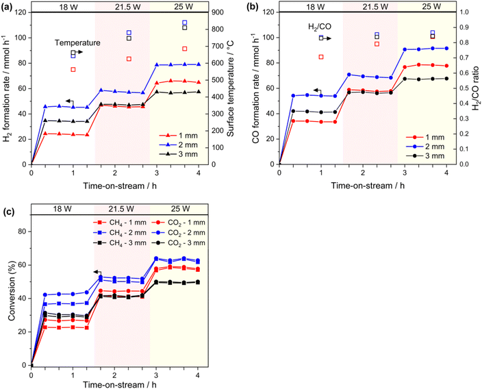
Additionally, the H2/CO ratio was lower than the stoichiometric value in DRM (i.e., 1, eqn (1), Fig. 3b, right axis). This could be interpreted by the simultaneous occurrence of side reactions such as reverse water gas shift reaction (eqn (6)).
| CO2 + H2 ⇄ H2O + CO, ΔH° = 41 kJ mol−1 | (6) |
Furthermore, the H2/CO ratio increased with increasing light power in all gap reactors, although the difference was slight in the 2-mm-gap and 3-mm-gap reactors. The trend is likely attributed to the thermodynamic equilibrium because the H2/CO ratio increases at higher temperatures (Fig. S3†). The light-to-fuel conversion efficiency (η) in the 2-mm-gap reactor was 6.0% at 25 W at the conversion range of approximately 60% (Fig. 3c, S4†).
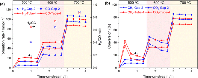
To investigate the performance of this reactor system in the absence of light irradiation, we conducted thermal DRM activity tests using an electric furnace from 500 to 700 °C. In these tests, we used the 2-mm-gap reactor and tube reactor (inner diameter: 4 mm) without altering the catalyst amount (60 mg) and the reaction gas feed. The formation rates of H2 and CO (Fig. 4) and conversions of CH4 and CO2 increased with rising the reaction temperature. Moreover, as the reaction temperature increased, the H2/CO ratio increased, which was consistent with the photothermal activity test using the 1-mm-reactor (Fig. 3b and c, right axis) and was not observed in the 3-mm-gap reactor. This comparison suggests that, at the increased gap thickness of 3 mm, reverse or side reactions proceeded at the lower temperature zone of the back side of the reactor.
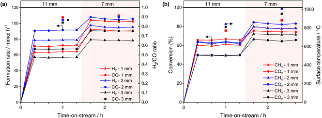
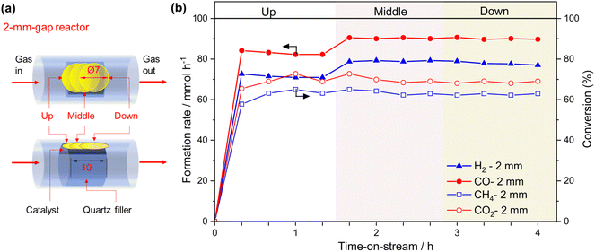
The impact of the temperature gradient perpendicular to the light irradiation direction on the catalytic activity was evaluated using the 2-mm gap reactor by irradiating different positions of the catalyst bed with a 7-mm-spot (Fig. 6a). Light irradiation to the middle and downstream positions resulted in slightly higher formation rates of CO and H2 compared to the upstream irradiation (Fig. 6b). We previously reported irradiation to the downstream position produced twice the conversion and formation rates compared with irradiating the upstream position using a flat type reactor (irradiation area: 20 mm × 20 mm, thickness: 1 mm, light spot diameter: 7 mm Φ).15 The difference in the performance was attributed to the reverse reaction being promoted at a low-temperature downstream zone when the upstream zone was irradiated.15 In the present experiment, the size of the irradiation area (8 mm × 10 mm, Fig. 1) was nearly consistent with the light spot diameter (7 mm Φ), which is likely to reduce the positional effect of the light spot on the catalytic activity. It is worth mentioning that the cross-sectional area of the catalyst zone in the gap reactor is easily adjusted by modifying the inner diameter of the quartz tube and the size of the inner filler. This flexibility provides a significant advantage in avoiding the mismatches of the light absorbing area and the light spot.
![[thin space (1/6-em)]](https://www.rsc.org/images/entities/char_2009.gif) 38 or 6 kW
38 or 6 kW![[thin space (1/6-em)]](https://www.rsc.org/images/entities/char_2009.gif) 39). Separately, the existence of a temperature gradient (> approximately 200 °C) was confirmed using thermocouples under a flow of inert gas, even in the case of the 2-mm-gap reactor (ESI Note 1†). These results indicate that the gap reactor mitigated the temperature gradient, resulting in high conversion even under relatively low light irradiation conditions by suppressing the reverse reaction at the low-temperature zone. Additionally, we confirmed that the conversion of CO2 and CH4 was approximately 60% when using the 4-mm-tube reactor (Fig. S5†), where the same catalyst amount and bed length were employed as used in the 2-mm-gap reactor.
39). Separately, the existence of a temperature gradient (> approximately 200 °C) was confirmed using thermocouples under a flow of inert gas, even in the case of the 2-mm-gap reactor (ESI Note 1†). These results indicate that the gap reactor mitigated the temperature gradient, resulting in high conversion even under relatively low light irradiation conditions by suppressing the reverse reaction at the low-temperature zone. Additionally, we confirmed that the conversion of CO2 and CH4 was approximately 60% when using the 4-mm-tube reactor (Fig. S5†), where the same catalyst amount and bed length were employed as used in the 2-mm-gap reactor.
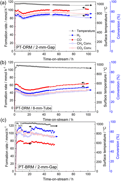
Coke formation is one of the crucial challenges in PT-DRM. Based on elemental analysis, the amount of deposited coke after 100-hours-reaction was 17 mg (28.3 wt%) in the 2-mm-gap reactor and 115 mg (33.8 wt%) in the 8-mm tube reactor. The reduced coke formation can be attributed to the decreased temperature gradient because the coke formation is thermodynamically favorable at lower temperatures.
The addition of steam into the reaction feed in DRM (i.e., bi-reforming) is an effective strategy for reducing the coke formation and controlling the H2/CO ratio in the produced syngas.40,41 To check the applicability of this gap reactor, we conducted the photothermal bi-reforming of methane (PT-BRM) using a reaction feed of CH4 (22.5 mL min−1)/CO2 (12.0 mL min−1)/H2O (11.0 mL min−1)/N2 (10.0 mL min−1)/Ar (145 mL min−1). In the PT-BRM test, the rH2 increased significantly to over 100 mmol h−1 compared to the PT-DRM results (Fig. 7c). The CO2 and CH4 conversions were 75% and 73%, respectively, after 52 h of the activity test. The H2/CO ratio was 1.4 under PT-BRM conditions, substantially higher than that observed under PT-DRM conditions. Furthermore, the amount of the deposited coke after 52 h was only 0.6 wt%, indicating a significant reduction of coke formation due to steam addition. These results suggest that combining the developed gap reactor with PT-BRM could pave the way for highly active and stable solar reforming systems. Additionally, this study underscores the critical role of reactor design in photothermal reactions and provides a novel method for developing efficient photo-reactors.
4. Conclusions
In photothermal dry-reforming of methane (PT-DRM), the temperature gradient induced by light irradiation poses a significant challenge, as catalysts at a low-temperature zone promote the reverse reaction, thereby reducing overall catalytic performance. This study demonstrated the effectiveness of a novel gap reactor with controllable thickness for mitigating a temperature gradient and enhancing catalytic performance in PT-DRM. Using the gap reactor, approximately 78% of CO2 conversion and 72% of CH4 conversion were achieved over 100 hours on the Co–Ni@SiO2 catalyst developed by our group previously. Compared to the conventional tube reactors, the gap reactor exhibited substantially higher conversion and long-term stability. Furthermore, the developed gap reactor showed excellent catalytic performance for the photothermal bi-reforming of methane, with suppressed coke formation to only 0.6 wt% after approximately 50 hours of reaction. These findings highlight the potential of this novel gap reactor design for photothermal catalysis, offering a promising pathway for advancing catalytic reforming processes powered by solar energy.Data availability
The authors confirm that the data supporting the findings of this study are available within the article and its ESI.†Author contributions
H. A. E. and A. Y. conceptualized this work. H. A. E. conducted the experiments and wrote this manuscript with support from A. Y and H. Y. A. Y. supervised this project with advice from H. Y. The manuscript was written through contributions of all authors and all authors have given approval to the final version of the manuscript.Conflicts of interest
The authors declare that a patent application (Japanese Patent Application No. 2024-192704) has been filed based on the results described in this manuscript.Acknowledgements
This work was financially supported by the Scientific Research (B) (24K01527) from the Japan Society for the Promotion of Science. The TEM observations were supported by Advanced Research Infrastructure for Materials and Nanotechnology (ARIM) in Japan (proposal numbers: JPMXP1224KT0010 and JPMXP1224KT0041).References
- T. N. From, B. Partoon, M. Rautenbach, M. Østberg, A. Bentien, K. Aasberg-Petersen and P. M. Mortensen, Chem. Eng. J., 2024, 479, 147205 CrossRef CAS.
- S. T. Wismann, J. S. Engbæk, S. B. Vendelbo, F. B. Bendixen, W. L. Eriksen, K. Aasberg-Petersen, C. Frandsen, I. Chorkendorff and P. M. Mortensen, Science, 2019, 364, 756–759 CrossRef CAS PubMed.
- L. E. Sandoval-Diaz, R. Schlogl and T. Lunkenbein, Catalysts, 2022, 12, 465 CrossRef CAS.
- J. Y. Y. Loh, A. Wang, A. Mohan, A. A. Tountas, A. M. Gouda, A. Tavasoli and G. A. Ozin, Adv. Sci., 2024, 11, 2306604 CrossRef CAS PubMed.
- Y. Jiang, S. Li, Y. Fan and Z. Tang, Angew. Chem., Int. Ed., 2024, 63, e202404658 CrossRef CAS PubMed.
- X. Li, C. Wang and J. Tang, Nat. Rev. Mater., 2022, 7, 617–632 CrossRef CAS.
- S. A. M. Said, M. Waseeuddin and D. S. A. Simakov, Renewable Sustainable Energy Rev., 2016, 59, 149–159 CrossRef CAS.
- E. J. Sheu, E. M. A. Mokheimer and A. F. Ghoniem, Int. J. Hydrogen Energy, 2015, 40, 12929–12955 CrossRef CAS.
- M. Romero and A. Steinfeld, Energy Environ. Sci., 2012, 5, 9234–9245 RSC.
- E. Casati, L. Allgoewer and A. Steinfeld, Device, 2024, 2, 100399 CrossRef.
- W. Sarwana, D. Takami, A. Yamamoto and H. Yoshida, Catal. Sci. Technol., 2023, 13, 1755–1762 RSC.
- A. Tavasoli, A. Gouda, T. Zahringer, Y. F. Li, H. Quaid, C. J. Viasus Perez, R. Song, M. Sain and G. Ozin, Nat. Commun., 2023, 14, 1435 CrossRef CAS PubMed.
- A. Tavasoli and G. Ozin, Joule, 2018, 2, 571–575 CrossRef.
- X. Tian and F. Wang, Sep. Purif. Technol., 2025, 354, 128799 CrossRef CAS.
- H. A. El-Naggar, D. Takami, H. Asanuma, T. Hirata, H. Yoshida and A. Yamamoto, ChemCatChem, 2024, e202401396 Search PubMed.
- D. Takami, J. Tsubakimoto, W. Sarwana, A. Yamamoto and H. Yoshida, ACS Appl. Energy Mater., 2023, 6, 7627–7635 CrossRef CAS.
- J. Zhang, K. Xie, Y. Jiang, M. Li, X. Tan, Y. Yang, X. Zhao, L. Wang, Y. Wang, X. Wang, Y. Zhu, H. Chen, M. Wu, H. Sun and S. Wang, ACS Catal., 2023, 13, 10855–10865 CrossRef CAS.
- D. Takami, Y. Ito, S. Kawaharasaki, A. Yamamoto and H. Yoshida, Sustainable Energy Fuels, 2019, 3, 2968–2971 RSC.
- T. Xie, Z.-Y. Zhang, H.-Y. Zheng, K.-D. Xu, Z. Hu and Y. Lei, Chem. Eng. J., 2022, 429, 132507 CrossRef CAS.
- P. Kant, S. Liang, M. Rubin, G. A. Ozin and R. Dittmeyer, Joule, 2023, 7, 1347–1362 CrossRef CAS.
- W. K. Fan and M. Tahir, Chem. Eng. J., 2022, 427, 131617 CrossRef CAS.
- I. V. Yentekakis, P. Panagiotopoulou and G. Artemakis, Appl. Catal., B, 2021, 296, 120210 CrossRef CAS.
- H. Wu, J. Liu, H. Liu and D. He, Fuel, 2019, 235, 868–877 CrossRef CAS.
- C. Wang, Y. Qiu, X. Zhang, Y. Zhang, N. Sun and Y. Zhao, Catal. Sci. Technol., 2018, 8, 4877–4890 RSC.
- M. Yang, P. Jin, Y. Fan, C. Huang, N. Zhang, W. Weng, M. Chen and H. Wan, Catal. Sci. Technol., 2015, 5, 5095–5099 RSC.
- Y. Li, J. Hao, H. Song, F. Zhang, X. Bai, X. Meng, H. Zhang, S. Wang, Y. Hu and J. Ye, Nat. Commun., 2019, 10, 2359 CrossRef PubMed.
- B. J. McBride, Computer Program for Calculation of Complex Chemical Equilibrium Compositions and Applications, NASA Lewis Research Center, 1996 Search PubMed.
- G. Baffou, I. Bordacchini, A. Baldi and R. Quidant, Light:Sci. Appl., 2020, 9, 108 CrossRef PubMed.
- T. Sukonket, A. Khan, B. Saha, H. Ibrahim, S. Tantayanon, P. Kumar and R. Idem, Energy Fuels, 2011, 25, 864–877 CrossRef CAS.
- M. A. Vasiliades, P. Djinović, L. F. Davlyatova, A. Pintar and A. M. Efstathiou, Catal. Today, 2018, 299, 201–211 CrossRef CAS.
- P. Djinović and A. Pintar, Appl. Catal., B, 2017, 206, 675–682 CrossRef.
- H. Huang, M. Mao, Q. Zhang, Y. Li, J. Bai, Y. Yang, M. Zeng and X. Zhao, Adv. Energy Mater., 2018, 8, 1702472 CrossRef.
- S. Shoji, X. Peng, A. Yamaguchi, R. Watanabe, C. Fukuhara, Y. Cho, T. Yamamoto, S. Matsumura, M.-W. Yu, S. Ishii, T. Fujita, H. Abe and M. Miyauchi, Nat. Catal., 2020, 3, 148–153 CrossRef CAS.
- X. Liu, H. Shi, X. Meng, C. Sun, K. Zhang, L. Gao, Y. Ma, Z. Mu, Y. Ling, B. Cheng, Y. Li, Y. Xuan and Y. Ding, Sol. RRL, 2021, 5, 2100185 CrossRef CAS.
- S. Wu, G. Ji, P. Qiu, Q. Hu, J. Tian and Y. Li, Sol. RRL, 2022, 6, 2200369 CrossRef CAS.
- Z. Xie, Y. Li, Z. Zhou, Q. Hu, J. Wu and S. Wu, J. Mater. Chem. A, 2022, 10, 7099–7110 RSC.
- Z. Cui, Q. Hu, Y. Li, J. Wu, X. Yu, H. Cao, L. Ji, M. Zhong and Z. Chen, Appl. Catal., B, 2024, 350, 123917 CrossRef CAS.
- T. Kodama, H. Ohtake, K. Shimizu and Y. Kitayama, Energy Fuels, 2002, 16, 1016–1023 CrossRef CAS.
- T. M. Abdellateif, J. Sarwar, E. C. Vagia and K. E. Kakosimos, Chem. Eng. J., 2023, 452, 139190 CrossRef CAS.
- K. Jabbour, J. Energy Chem., 2020, 48, 54–91 CrossRef.
- A. Ali Khan, M. Tahir and N. Khan, Energy Convers. Manage., 2023, 286, 117021 CrossRef CAS.
Footnote |
| † Electronic supplementary information (ESI) available. See DOI: https://doi.org/10.1039/d4se01830c |
| This journal is © The Royal Society of Chemistry 2025 |

