 Open Access Article
Rolling of stimuli-bent cylindrical robots using contact finite element simulations†
Shaobo
He
ae,
Hao
Yu
b,
M. B. N.
Kouwenhoven
 bc,
Paolo
Paoletti
e,
Marjolein
Dijkstra
d and
Chen
Xuan
 *acdfg
aDepartment of Foundational Mathematics, Xi’an Jiaotong-Liverpool University, Suzhou, 215123, China. E-mail: Chen.Xuan@xjtlu.edu.cn
bDepartment of Physics, Xi’an Jiaotong-Liverpool University, Suzhou, 215123, China
cDepartment of Mathematical Sciences, University of Liverpool, Liverpool L69 3BX, UK
dSoft Condensed Matter & Biophysics group, Debye Institute for Nanomaterials Science, Utrecht University, Princetonplein 1, 3584 CC Utrecht, The Netherlands
eSchool of Engineering, University of Liverpool, Liverpool L69 3BX, UK
fXJTLU-JITRI Academy of Industrial Technology, Xi’an Jiaotong-Liverpool University, Suzhou 215123, China
gAdvanced Materials Research Center, Department of Chemistry and Materials Science, School of Science, Xi’an-Jiaotong Liverpool University, Suzhou, 215123, China
First published on 11th March 2025
Abstract
Curved cylinders, if rigid, cannot roll on a surface like straight cylinders, but soft cylinders bent by specific stimuli can! Studying the autonomous locomotion of these soft robots and their interactions with the environment using finite element analysis is challenging due to the complex multiphysics of stimuli-responsive soft materials and nonlinear contact mechanics. In this pioneering work, we simulate the rolling of stimuli-bent cylinders on a surface using contact finite elements and introduce a simple yet effective pseudo-thermal field method. Our approach successfully reproduces several modes of autonomous locomotion observed experimentally, including phototropic locomotion, phototropic climbing on a slanted surface, steering under partial illumination, and backward rolling under alternating heat-light stimuli. Parametric analysis demonstrates strong agreement between the experiments and our numerical results, validating the effectiveness of our approach. This study reveals the intriguing and highly nonintuitive dynamics of photo- or thermally bent cylindrical soft robots, and serves as a paradigm for modelling and simulating such rolling robots.
1 Introduction
Soft actuators made from stimuli-responsive soft gels1–9 or liquid crystals (LCs)10–14 have been widely studied due to their potential to enhance production efficiency and reduce human exposure to hazardous environments.15 Liquid crystal elastomers (LCEs), in particular, exhibit remarkable responses to stimuli such as force, heat, and light10,16–36 making them ideal candidates for developing diverse structures capable of various motions17,37–41 and for use in soft robotics.42–46 Recent groundbreaking discoveries in continuous autonomous rolling of soft cylindrical robots on surfaces composed of photothermal or humidity-sensitive materials have opened up new possibilities for smart actuation controlled by light, heat, or humidity.15,47–49 For instance, previous studies have shown that a cylindrical monodomain LCE rod can continuously roll on a flat surface (up to 6 mm s−1) under uniform light illumination or elevated temperatures.47 The rolling motion can be further controlled by combining thermal and optical stimuli. Similarly, controlled movements, such as phototropic locomotion on both flat and inclined surfaces, have been demonstrated with fiber-based actuators (reaching a speed up to 1.7 mm s−1 with greatest work density of 0.179 kJ kg−1 and power density of 24.28 W kg−1), highlighting their extraordinary actuation capabilities for advanced applications.15 Distinct rolling behaviours have also been observed when nylon and polydimethylsiloxane (PDMS) fibers (4 mm s−1) are placed on a heated plate (while storing elastic energy density of 300 kJ m−3).48,49 Other works on soft actuators investigate rectilinear motion, such as the curling of polyurethane (PU) hydrogel strips,50 the crawling of LC network films51 and the squeezing of arc-shaped robots made from LCE–carbon nanotubes52 using “bow-shaped” bimorph actuators that bend or “ring-shaped” actuators that roll. These experiments lay a solid foundation for designing and fabricating multi-functional soft robotic vehicles.Experiments with autonomous rolling in soft robots, driven by light, heat, or humidity, vividly demonstrate various locomotion mechanisms, drawing the attention of theorists who analyse these behaviours analytically or numerically. A coupled photo-chemo or thermo-mechanical model has been developed to account for the contributions of photo-chemo-mechanical actuation to the overall deformation, implemented through specific temperature settings in ABAQUS.53,54 The untethered rolling of ring-shaped soft machines subject to light illumination is reproduced through finite element analysis (FEA) showing how the illumination angle affects inhomogeneous deformation and rolling torque.55 Simulations of light-induced locomotion with complex geometries such as 6-lobed LCE loops56 and articulated soft robots,57 explore multimodal patterns and reveal intricate interactions between the soft robots and their surrounding environment.58,59 The deformation and stress distributions have been numerically analyzed for thick-walled cylindrical rods60 and hollow torus motors.61 Based on these theoretical models,60,61 the lateral curvature, out-of-plane bending moments, and the effective driving moments resulting from inclined illumination, are numerically calculated, allowing the prediction of the rolling velocity of LCE rods under specific resistance moments and light intensities. However, a full understanding of the rolling dynamics of stimuli-responsive cylinders in contact with a surface is still lacking. While analytic models have been explored the steady-state rolling of cylinders48,49,62,63 finite element analysis (FEA) of robot-substrate contact, has not yet been conducted, leaving a gap in understanding the entire dynamical process—from the initial bending of a straight cylinder to the onset of rolling and subsequent motion. Simulations using contact FEs of stimuli-responsive cylinders rolling on a surface are still lacking yet it is a necessary approach for advancing our understanding of animal locomotion and rectilinear crawling via proprioception.64 Nonetheless, the inherent complexity of stimuli-responsive materials presents significant challenges for FE simulations in studying the rolling dynamics of such soft robots.
Inspired by the seminal experimental and theoretical work in ref. 15, 47–49, 62 and 63, this paper investigates nonmechanically induced locomotion of soft cylinders through FE simulation. The approach involves both robot-substrate contact and the complex nonlinear transient response of soft actuators to their external environment. To the best of our knowledge, no previous studies have simulated the rolling of nonmechanically bent cylinders on a surface using contact finite elements. Furthermore, this work is the first to achieve stimuli-responsive bending due to an eigenstrain gradient through spatially differential thermal expansion coefficients in FEA. In our FEA, the nonmechanical load is implemented using an Eulerian implementation that applies a transient eigenstrain gradient while tracking the moving robot, resulting in continuous locomotion. Our approach shows a paradigm for modelling and simulating such rolling soft robots.
The remaining sections are organized as follows. Section 2 introduces our modeling approach for nonmechanically induced responses and the corresponding FE implementation. Section 3 shows our FE simulation results of various locomotion modes of photo- or thermally bent soft cylindrical robots, which qualitatively reproduce the experimental observations. Section 4 performs a parametric study and compares our FEA of the above photo- or thermally induced locomotion with experimental results in a quantitative manner, capturing some key features in the parameter space to aid in the control of rolling motion. Finally, Section 5 presents our conclusions.
2 Modelling of nonmechanically induced response and FE implementation
2.1 Modelling of nonmechanically induced response
Fig. 1a illustrates a stimuli-bent soft cylindrical robot. A global (x, y, z) coordinate system is established, with the contact surface defined as the x–y plane. Here, x aligns with the longitudinal direction of the initially undeformed straight cylinder, and z is the coordinate normal to the x–y plane, with the deflection curve of the central line of the cylinder denoted by y(x). Additionally, we use t, n, b to represent the unit basis vectors of a local coordinate system where t is tangent to the local longitudinal direction of the cylinder, n represents the in-plane normal, and b indicates the out-of-plane normal. As shown in Fig. 1b, we take a stimuli-bent differential element to conduct a free-body diagram, with the bending moment along n acting on the top end of the differential element Mn and on the bottom end of it Mn + dMn. The local bending moment Mn on a cylindrical cross-section is calculated as a lever arm-weighted integral of the stress component σt along t over its cross-section | (1) |
The soft robot in question is assumed to follow a linear constitutive relation with the stress tensor σ
| σ = C: (ε − εeig), | (2) |
| εeig = εeig(d⊗d – νsl⊗l − vsm⊗m), | (3) |
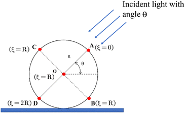
Light absorption within the solid material can be modelled using exponential decay according to Beer's law, although deviations from Beer's law may need to be considered under strong illumination. When light is shone on any circular cross-section of the cylinder, as shown in Fig. 2, it produces a complex distribution of light intensity throughout the cross-section due to the angular dependence as well as the propagation depth ξ, associated with non-perpendicular illumination. Except for the line AD, which lies precisely along the incidence, the entire cross-section is oblique to the incident light. As the simplest possible spatial distribution assumption, the light intensity propagating through can be considered to decrease geometrically based on a simple decomposition of the local Poynting flux (referred to hereafter as cosine angular dependence). Under the Beer's law limit, the photo-induced strain (eigenstrain) is directly proportional to the light intensity, therefore exhibiting the same depth profile as the light intensity. It turns out that this eigenstrain profile with the above cosine angular dependence results in an effective photo bending moment that is very close to that arising from an angularly independent eigenstrain profile (identical to an angularly independent light intensity profile after scaling), where the light intensity only decays exponentially with ξ. That these two models nearly coincide numerically is not surprising, as the bending moment is minimally affected by the regions around the line BC, which contribute the most to the angular dependence (Fig. 2). For simplicity, we adopt an eigenstrain profile that decays exponentially with ξ for the cylindrical robot, as it brings little noticeable quantitative differences in rolling behaviour.
Our eigenstrain modelling approach can be applied to thermally, humidity, and photo-driven response in both isotropic and anisotropic materials, with the eigenstrain εeig and effective stimuli Poisson's ratio νs adjusted accordingly. For thermal actuation, the response depends on the sign of the thermal expansion coefficient, with εeig < 0 for materials such as nylon fibers and εeig > 0 for materials like PDMS rods, as reported in ref. 48 and 49. In the case of humidity-driven actuation, the response depends on the relative chemical potential between the gel and the surrounding liquid, with εeig > 0 for uncooked spaghetti placed on a water surface, as reported in ref. 48 and 49. Since heat transfer in thermal actuation and solvent migration in humidity-driven actuation are both diffusion processes, it is reasonable to adopt an exponential depth profile for the eigenstrain, similar to photo actuation. The only limitation is that this exponential depth profile is assumed to be static, as the heat or solvent diffusion is considered negligible in terms of time to affect the deformation profile during the fast rolling of each cross-section with a continuously varying contact area on the surface.
2.2 FE Implementation with the pseudo thermal field method
In a typical FE software package, including ABAQUS, there is no module that directly implements photomechanical response. In this paper, we propose a pseudo-thermal field method, where photo-induced strains, such as those resulting from a trans–cis photo reaction, are implemented as pseudo-thermal strains under pseudo-temperature rise ΔT| εeig = αtΔT, −vsεeig = αnΔT = αbΔT, | (4) |
 | (5) |
Our pseudo-thermal field method also works for thermally induced actuation with heat processes that are much slower than rolling. In this limit, heat gives rise to eigenstrain that can well be approximated by an exponential profile, similar to how we model photo decay.
All simulations in this paper use surface-to-surface contact and finite sliding in ABAQUS. Friction between the cylinder and the substrate is modelled using the Penalty method.66 The cylinder is meshed with 8-node linear brick (C3D8) elements, while the substrate is treated as a rigid body. Mesh convergence is verified for all simulations. Gravity and normal contact force, essential for rolling, are considered in all simulations throughout. The optical penetration depth is taken as d = R in all simulations.
To demonstrate typical eigenstrain and geometric strain distributions within the framework of our modelling approach, we consider a cylindrical robot that responds to photo illumination with an incidence angle of θ = π/4 by bending to the right in the x–y plane. Fig. 3 shows the distributions of eigen- and geometric strain across several cross sections of the cylinder. The eigenstrain component along longitudinal direction t decays exponentially in the light incident direction as shown in Fig. 3a. This distribution of eigenstrain gives rise to a phototropic bend. The exact orientation of the cylinder in response to the light is governed by the geometric and material parameters of the cylinder, as well as the constraint from the substrate. Here, we focus our attention on bending within the x–y plane, which is also the case in experiments. The geometric strain along t (Fig. 3b) shows a gradient predominantly along n (equivalently y for small deflection bend within the x–y plane) and is nearly linear in n, indicating that the longitudinal deformation of the cylindrical robot in response to the photo illumination closely follows that of a classical vibrating beam under an approximate uniaxial stress state.
3 Locomotion of rolling cylindrical robots induced by photo or thermal stimuli
In this section, various locomotion modes of a cylindrical robot are simulated using FEA based on the technical details from the previous section and compared with experimental results3.1 Phototropic locomotion on a horizontal plane
As observed in the experiments,15 a soft LCE cylindrical fibre can exhibit quick and flexible locomotion toward light under steady illumination. As illustrated in Fig. 4a, when the incident light is imposed at a certain angle, the cylinder can be activated to roll toward the light as soon as it is illuminated, because its light-induced inhomogeneous deformation causes the cylinder to bend towards the light. As the cylinder rolls forward, its unexposed side becomes illuminated while the originally exposed area is shaded. With the light source moving along with the cylinder, the cylinder continues its phototropic movement. | ||
| Fig. 4 Phototropic locomotion on a horizontal plane. (a) Photographs captured during the locomotion from the experiments in ref. 15; (b) FE simulation. The experimental and FE parameters are: length 13 mm, diameter 0.58 mm, E = 10 MPa, ρ = 106 kg m−3. See also the supplementary animations (ESI†). | ||
The FEA model uses the same geometry and material parameters as those in the experiment. A cylindrical robot with a diameter of 0.58 mm, and a length of 13 mm is simulated. Mesh convergence for the cylinder is achieved with 12![[thin space (1/6-em)]](https://www.rsc.org/images/entities/char_2009.gif) 080 elements. In this simulation, the incident light is assumed to be diffusive and sufficiently large to expose the entire length of the cylinder. Fig. 4b presents snapshots from the simulation of the continuous rolling process under moving light. The contour plot shows the distribution of longitudinal eigenstrain in contrast to the original shape and position of the cylinder, which is shown in grey. In this simulation, the material is assumed to contract under light, generating eigenstrain that results in a net photo rolling torque to the right. Consequently, the entire cylinder rolls in the concave direction, in accordance with the experiments.15,48
080 elements. In this simulation, the incident light is assumed to be diffusive and sufficiently large to expose the entire length of the cylinder. Fig. 4b presents snapshots from the simulation of the continuous rolling process under moving light. The contour plot shows the distribution of longitudinal eigenstrain in contrast to the original shape and position of the cylinder, which is shown in grey. In this simulation, the material is assumed to contract under light, generating eigenstrain that results in a net photo rolling torque to the right. Consequently, the entire cylinder rolls in the concave direction, in accordance with the experiments.15,48
3.2 Phototropic locomotion on an inclined surface
An LCE cylindrical fibre can climb on a slope under light illumination,15 proving excellent locomotion and flexible adaptability to different environments controlled by light, as shown in Fig. 5a. In our simulation, we also successfully reproduce this phototropic climb on a slanted surface, as shown in Fig. 5b. The longitudinal eigenstrain follows an exponential distribution across each cross-section, with the exposed surface experiencing the largest contraction and the shaded area the smallest contraction, similar to what is observed in phototropic locomotion on a horizontal plane. This eigenstrain again leads to a net photo rolling torque directed upwards along the slope, strong enough to overcome gravity and allow the cylinder to climb up the slope. These motions indicate the great potential of this soft actuator working as a transportation vehicle.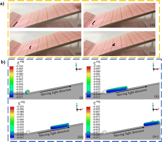 | ||
| Fig. 5 Phototropic locomotion on an inclined surface. (a) Photographs from the experiments in ref. 15; (b) FE simulation. The experimental and FE parameters are: length 13 mm, diameter 0.58 mm, E = 10 MPa, ρ = 106 kg m−3. See also the supplementary animations (ESI†). | ||
3.3 Steering under partial illumination
Unlike the aforementioned motions, where the locomotion is rectilinear, a cylinder undergoes steering movements while rolling on a surface under partial illumination,15 as shown in Fig. 6a. To reproduce this effect, we expose only a part of the cylinder to light in Fig. 6b, meaning the unexposed part does not respond to light at all. In our FEA model, only two thirds of the cylinder is illuminated. The exposed part bends towards the light while the unexposed part would remain straight where there no internal stress exerted by the exposed part. The ±x symmetry seen in phototropic locomotion on a horizontal or slanted surface is no longer present, causing the entire cylinder to rotate clockwise. A tangent line, as shown in (ii) of Fig. 6b, can be drawn to measure the rotation angle. The supplementary animations (ESI†) also suggest that with two thirds illuminated, the cylinder can rotate by 45 degrees clockwise, successfully demonstrating its controllability to achieve steering motion. | ||
| Fig. 6 Steering under partial illumination. (a) Photographs when only one end is exposed to light from the experiments in ref. 15; (b) FE simulation. The experimental and FE parameters are: length 7 mm, diameter 0.58 mm, E = 10 MPa, ρ = 106 kg m−3. See also the supplementary animations (ESI†). | ||
3.4 Symmetry breaking: rolling to the left or right?
When photo or thermal illumination is oblique to a horizontal substrate surface, the cylindrical robot on the substrate is able to roll spontaneously, with the rolling direction determined by the angle of illumination. However, when the illumination is normal to the surface, the cylinder bends straight up or down and may not be able to roll to the left or right unless there is something to break the symmetry. As reported in experiments,47 symmetry breaking can rely on initial imperfections, such as a slight curvature introduced during fabrication or simply a gentle push, as shown in Fig. 7a.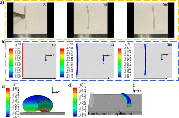 | ||
| Fig. 7 Rolling while heated from below. (a) Photographs of a straight rod with negative thermal expansion coefficients rolling on a hot plate after an initial push to the right from the experiments in ref. 47; (b)–(d) FE simulation of a cylinder heated from below whose rolling direction is dictated by a slight push exerted after (c) which shows the initial thermally induced upward bend before the symmetry is broken by the slight push. (d) Takes a view different from those of (i)–(iii). The experimental and FE parameters are: length 70 mm, diameter 2.6 mm, E = 5 MPa, ρ = 103 kg m−3. See also the supplementary animations (ESI†). | ||
In our FEA for thermal actuation, the pseudo thermal expansion coefficients are assigned flipped exponential profiles to mimic thermal strains. As a result, an initially straight cylinder, as shown in (i) of Fig. 7b, responds to heat applied vertically from below, leading to a longitudinal eigen contraction that is largest at the bottom and smallest at the top, deforming the cylinder into an arc, as shown in Fig. 7c. When given a slight push from an instantaneous (rapidly removed) external force to the right, the cylinder drops to the right and continues rolling in that direction. Unlike the photo illumination from above in Fig. 4–6, where rolling occurs toward the concave direction, heat from a hot surface below causes the cylinder to roll toward the convex direction. The steady distributions of eigenstrain shown in Fig. 7b and d allow the cylinder to keep rolling without any sustained external force. This FE simulation shows that rolling under illumination normal to the surface may rely on symmetry breaking, such as a gentle push, efficiently reproducing the commonly practised experimental approach to break symmetry.
3.5 Backward rolling under heat-light alternating illumination
An interesting case of light-induced reverse rolling of an LCE-CNT composite rod on a hot plate is shown.47 As shown in Fig. 8a, when placed on a heated plate, the rod can roll continuously toward its convex direction to the right. However, when illuminated by light from the right, the rod slows down while reversing its concavity and finally back-rolls to the left. During this 2nd stage, the light, which is immediately turned on, inverts the eigen curvature, and the residual heat from below provides a driving bending moment across all cross sections, resulting in a rolling torque to the left.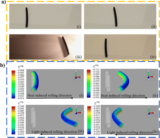 | ||
| Fig. 8 Under heat-light alternating illumination: (i) and (ii) heat induced rolling to the right and (iii) and (iv) light induced rolling to the left (a) An LCE-CNT composite rod on a hot surface from the experiments in ref. 47; (b) FE simulation. The experimental and FE parameters are: length 70 mm, diameter 2.6 mm, E = 5 MPa, ρ = 103 kg m−3. See also the supplementary animations (ESI†). | ||
To apply a thermal load on the cylinder from the hot surface below in our FEA, the eigenstrains, effectively the thermal expansion coefficients, are assigned flipped-over exponential profiles to mimic thermal strains, as shown in (i)–(ii) of Fig. 8b. With heat imposed from below, the rolling direction is toward the convex direction, in contrast to rolling toward the concave side observed under photo illumination from above, as seen in Fig. 4–6. During the 2nd stage of this simulation, light is applied from the right, however, to also account for the residual heat from below, photo-induced eigenstrains in (iii) and (iv) of Fig. 8b are imposed, resulting in a net rolling torque to the left. The reversal of rolling demonstrated in this simulation provides a feasible way to produce rolling patterns by combining light irradiation with a heated substrate.
The FEA results show good qualitative agreement with experimental observations, showcasing the effectiveness of our simple modelling approach and FE implementation in reproducing various locomotion patterns observed in experiments. This approach will serve as an excellent tool for predicting other locomotion behaviours in future work.
4 Parametric analysis in comparison with experiments
The qualitative comparison in the last section shows the feasibility of our FE simulation to reproduce experiment observations and predict other behaviours of a photo- or thermally induced rolling rod. In order to show the accuracy of our approach and obtain more insightful understanding, we explore the parameter space and quantitatively compare the simulation results with existing experimental data. Since stress and strain are hard to measure experimentally, researchers focus on the relationship between the rod's rolling velocity and the curvature of its deformed shape.47–49 They also compare the effects of the illumination angle, rod radius, and length. In this section, we will conduct parametric analysis in comparison with the experimental results.4.1 Relation between heat-induced rolling velocity and curvature
Fig. 9 presents the radius of curvature against rolling velocity for thermally induced rolling of LCE rods with three different diameters, compared with the experiments.47 Our simulations, which adopt the same material parameters, show that rolling velocity decreases monotonically with curvature, a trend consistent with most data points from experiments.47 To reach the same rolling velocity, a smaller rod's radius yields a smaller radius of curvature, hence a large curvature. That is because the thinner the rod, the more eigenstrain gradient arises, leading to a large bending curvature.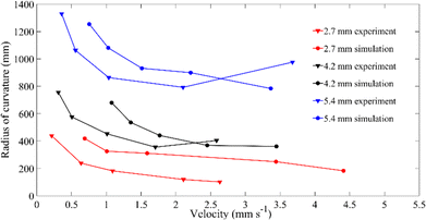 | ||
| Fig. 9 Comparison between experiment47 and simulation: on the relation between rolling velocity and radius of curvature for thermally induced rolling LCE rods. The experimental and FE parameters are as follows: length 70 mm, E = 5 MPa, ρ = 103 kg m−3; the diameter is 2.7 mm, 4.2 mm, 5.4 mm respectively. | ||
Apart from the experiment,47 involving the autonomous rolling of LCE rods on a hot plate, similar self-propulsion has been studied in linear fibers made of nylon.48,49 In this research, a nylon-6 fibre on a hot plate is observed to undergo rapid self-propulsion by rolling orthogonal to the fibre's long axis. Since nylon exhibits negative axial thermal expansion similar to LCEs, it can also undergo similar rolling behaviour when placed on a heated plate. In the FE simulation, we adopt the same nylon properties as those used in the experiment. The rolling direction is toward the cylinder's convex curvature, as seen in LCE rods under thermal actuation, due to the nylon's negative axial thermal expansion. The experimental and FEA results are plotted in Fig. 10, showing that the rolling velocity increases monotonically with curvature. This is in good agreement with our theoretical expectations, as curvature increases due to eigenstrain, the bending moment over the local cross-sections increases, resulting in a larger net rolling torque. Apart from the above materials with negative thermal expansion,48,49 also conduct similar experiments on materials with positive thermal expansion, such as polydimethylsiloxane rubber (PDMS), where rolling occurs toward the concave direction, as seen in photo-induced rolling. Possible dissipation factors, including rolling friction and other effects, could explain why the rolling velocities in our FEA, as shown in Fig. 9 and 10, appear faster than those observed in the experiments.47–49
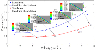 | ||
| Fig. 10 Comparison between experiments48,49 and simulations on the relation between heat-induced rolling velocity and curvature of a nylon fibre. The experimental and FE parameters: length 130 mm, diameter 0.6 mm, E = 100 MPa, ρ = 1.1 × 10³ kg m−3. | ||
4.2 Relation between light-induced rolling velocity and incident light angle
In photo-induced rolling, it has been found that the incident light angle plays a significant role in determining the rolling velocity and whether rolling occurs at all.47 In this section, our FE simulations, which adopt the same geometry as in ref. 47 present our FE data alongside with the experiment data in Fig. 11. It is found from both our FE simulations and experiments that the rolling velocity is maximised at a moderate illumination angle. When light is imposed at an angle around 60 degrees in the FEA, the mean rolling velocity can reach up to 1.35 mm s−1, which is also found to be the optimal angle for maximizing the rolling velocity in the experiments.47 In contrast, when the incident light is directed vertically onto the cylinder, i.e., θ = π/2, there is no noticeable movement of the cylinder, except for the two ends being lifted up slightly. For θ = π/2, the gradient of the eigenstrain is vertical, causing the centre of mass (CM) to rise only a little along the z-axis, preventing rolling from starting due to the lack of asymmetric deformation needed to shift the CM and cause the cylinder to drop to either side.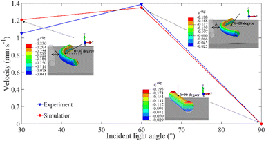 | ||
| Fig. 11 Comparison between experiment47 and simulation on the relation between light-induced rolling velocity and incident light angle. The experimental and FE parameters are: length 13 mm, diameter 0.58 mm, E = 10 MPa, ρ = 1.1 × 10⁶ kg m−3; the incident light angle is 30 degree, 60 degree, 90 degree respectively. | ||
4.3 Relation between light-induced rolling velocity and rod radius
It was found that the radius of three fabricated LCE rods, each 13 mm in length and with diameters of 0.58 mm, 0.76 mm, and 1.32 mm, affects the photo-induced locomotion.47 In our FEA, we adopt the same geometry, material properties, and illumination angle, and a similar correlation is plotted together with the experimental data in Fig. 12. When these three fibres are illuminated by light of the same intensity at the same angle, the rolling distance within the same time period decreases as the rod's radius increases. This occurs because thicker rods yield less photo bend and consequently, less rolling torque under the same optical penetration depth. The rolling velocity obtained from the FE simulation is measured by dividing the CM displacement δ (marked in Fig. 12) by the time duration. The rolling velocities obtained in our FEA appear faster than those observed in experiments, which could again be attributed to more dissipation in practical applications. | ||
| Fig. 12 Comparison between experiment47 and simulation on the relation between light-induced rolling velocity and radius of LCE rods. The experimental and FE parameters are: length 13 mm, E = 10 MPa, ρ = 1.1 × 10⁶ kg m−3; the diameter is 0.58 mm, 0.76 mm and 1.32 mm respectively. | ||
4.4 Relation between light-induced rolling velocity and rod length
Apart from the influence of fibre radius, the effect of fibre length has also been analysed. It was found that, with lengths of 8 mm, 13 mm, and 19 mm but the same diameter, a longer cylinder exhibits a slightly larger moving velocity,47 as plotted together with our FEA results under the same conditions in Fig. 13. While the rolling velocities obtained from our FEA are somewhat faster than those in ref. 47, possibly due to more dissipation in practical applications, the observed trend of rolling velocity weakly increasing with rod length can likely be attributed to higher light intensity being imposed near both ends of the rods, which is particularly significant for longer rods.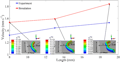 | ||
| Fig. 13 Comparison between experiment47 and simulation on the relation between light-induced rolling velocity and length. The experimental and FE parameters are: diameter 0.58 mm, E = 10 MPa, ρ = 1.1 × 10⁶ kg m−3, the length is 8 mm, 13 mm and 19 mm respectively. | ||
In this section, we study the parameter space and conduct quantitative comparisons with experiments, yielding quantitative correlations between key quantities that align well with experiments. We also identify interesting features that match our theoretical expectations. This strong agreement with experimental data highlights the effectiveness of our simple modelling approach and contact FE implementation, demonstrating that it can serve as a reliable tool for predicting other locomotion behaviours in future work.
5 Conclusions
This paper is the first to simulate non-mechanically induced rolling of soft cylindrical robots on a surface using FEA involving contact. Through a pseudo thermal field method and appropriate FEA techniques, we achieve both qualitative and quantitative agreement with existing experiments, demonstrating the effectiveness and reliability of our approach, along with the potential for predicting and designing rolling robots for future experiments.We develop a pseudo thermal field FE implementation for photo-induced deformation that introduces eigenstrain gradients in pseudo thermal expansion coefficients rather than in pseudo temperature. This successful FE implementation is perhaps the most natural way to avoid heat transfer in photo processes, which are intrinsically beyond consideration. We also offer room for this pseudo thermal field method to be applied to heat induced rolling, where heat transfer is much slower than, say rolling in our context. Additionally, the stimulus is automatically implemented in our contact FE simulations, following the robot wherever it moves.
The contact FE simulation successfully studies the autonomous locomotion of photo-, thermally or humidity-induced soft actuators like LCEs and others. This includes various locomotion patterns such as phototropic locomotion, phototropic climbing on a slanted surface, steering under partial illumination, and backward rolling under alternating heat and light illumination. We conduct a parametric study and quantitative comparisons to validate our FE approach and results. The agreement of our FE results with experimental data proves the feasibility and accuracy of our model and approach, showing great potential for predicting locomotion patterns in future work on such rolling systems and a paradigm for modelling and simulating such rolling robots.
Author contributions
S. He: formal analysis, investigation, methodology, software, validation, visualization, writing – original draft. H. Yu: conceptualization, supervision, writing – review & editing. M. B. N. Kouwenhoven: conceptualization, supervision, writing – review & editing. P. Paoletti: supervision, writing – review & editing. M. Dijkstra: supervision, writing – review & editing, funding acquisition. C. Xuan: conceptualization, formal analysis, funding acquisition, investigation, methodology, resources, supervision, writing – review & editing.Data availability
The data supporting this article have been included as part of the ESI.†Conflicts of interest
There are no conflicts to declare.Acknowledgements
This work is supported by the National Natural Science Foundation of China (Grant No. 12211530416 and 12002287); European Research Council (ERC) under the European Union's Horizon 2020 research and innovation programme (Grant agreement no. ERC-2019-ADG 884902 SoftML); Jiangsu Science and Technology Programme (Grant No. BK20200248); Jiangsu University Natural Science Research Programme (Grant No. 20KJB130001); Key Program Special Fund KSF-E-53 of XJTLU; Research Development Fund RDF-22-01-011 of XJTLU. For the purpose of open access, the authors have applied a Creative Commons Attribution (CC BY) licence to any Author Accepted Manuscript version arising.References
- A. Suzuki and T. Tanaka, Phase Transition in Polymer Gels Induced by Visible Light, Nature, 1990, 346, 345–347 Search PubMed.
- C. Xuan and L. Jin, Concurrent Reaction and Diffusion in Photo-Responsive Hydrogels, J. Mech. Phys. Solids, 2019, 124, 599–611 CrossRef.
- Y. Kim, J. van den Berg and A. J. Crosby, Autonomous Snapping and Jumping Polymer Gels, Nat. Mater., 2021, 20(12), 1695–1701 Search PubMed.
- H. Zhu, B. Xu, Y. Wang, X. Pan, Z. Qu and Y. Mei, Self-Powered Locomotion of a Hydrogel Water Strider, Sci. Rob., 2021, 6(53), eabe7925 CrossRef.
- P. R. Buskohl and R. A. Vaia, Belousov-Zhabotinsky Autonomic Hydrogel Composites: Regulating Waves via Asymmetry, Sci. Adv., 2016, 2(9), e1600813 Search PubMed.
- Y. Zhao, C. Xuan, X. Qian, Y. Alsaid, M. Hua, L. Jin and X. He, Soft Phototactic Swimmer Based on Self-Sustained Hydrogel Oscillator, Sci. Rob., 2019, 4(33), eaax7112 CrossRef PubMed.
- C. Xuan, Y. Zhou, Y. Zhao, X. He and L. Jin, Photodriven Self-Excited Hydrogel Oscillators, Phys. Rev. Appl., 2022, 17(1), 014007 CrossRef.
- C. Xuan and J. Biggins, Plateau-Rayleigh Instability in Solids Is a Simple Phase Separation, Phys. Rev. E, 2017, 95(5), 053106 Search PubMed.
- C. Xuan and J. Biggins, Finite-Wavelength Surface-Tension-Driven Instabilities in Soft Solids, Including Instability in a Cylindrical Channel through an Elastic Solid, Phys. Rev. E, 2016, 94(2), 023107 CrossRef.
- C. Modes and M. Warner, Shape-Programmable Materials, Phys. Today, 2016, 69(1), 32–38, DOI:10.1063/PT.3.3051.
- M. J. Stephen and J. P. Straley, Physics of Liquid Crystals, Rev. Mod. Phys., 1974, 46(4), 617–704 CrossRef.
- S. Belli, S. Dussi, M. Dijkstra and R. van Roij, Density Functional Theory for Chiral Nematic Liquid Crystals, Phys. Rev. E, 2014, 90(2), 020503 CrossRef.
- S. Belli, A. Patti, M. Dijkstra and R. van Roij, Polydispersity Stabilizes Biaxial Nematic Liquid Crystals, Phys. Rev. Lett., 2011, 107(14), 148303 CrossRef PubMed.
- A. Patti, S. Belli, R. van Roij and M. Dijkstra, Relaxation Dynamics in the Columnar Liquid Crystal Phase of Hard Platelets, Soft Matter, 2011, 7(7), 3533–3545 RSC.
- Y. Yu, L. Li, E. Liu, X. Han, J. Wang, Y.-X. Xie and C. Lu, Light-Driven Core-Shell Fiber Actuator Based on Carbon Nanotubes/Liquid Crystal Elastomer for Artificial Muscle and Phototropic Locomotion, Carbon, 2022, 187, 97–107 CrossRef.
- Y. Zhang, C. Xuan, Y. Jiang and Y. Huo, Continuum Mechanical Modeling of Liquid Crystal Elastomers as Dissipative Ordered Solids, J. Mech. Phys. Solids, 2019, 126, 285–303 CrossRef.
- C. Ahn, X. Liang and S. Cai, Inhomogeneous Stretch Induced Patterning of Molecular Orientation in Liquid Crystal Elastomers, Extreme Mech. Lett., 2015, 5, 30–36 CrossRef.
- M. Barnes, F. Feng and J. S. Biggins, Surface Instability in a Nematic Elastomer, Phys. Rev. Lett., 2023, 131(23), 238101 CrossRef.
- D. S. Polat, M. Zmyślony, J. S. Biggins and D. Liu, Spontaneous Snap-through of Strongly Buckled Liquid Crystalline Networks, Extreme Mech. Lett., 2024, 68, 102149 CrossRef.
- Z. Peng, Y. Jiang, Y. Chen and Y. Huo, Attenuating Liquid Crystal Elastomers’ Stress Concentration by Programming Initial Orientation, Int. J. Mech. Sci., 2023, 249, 108274 CrossRef.
- S. Zhao, Y. Chen and Y. Huo, Formation of Lamellar Domains in Liquid Crystal Elastomers under Compression, Int. J. Mech. Sci., 2023, 247, 108185 CrossRef.
- Z. Zhang and Y. Huo, Programmable Mechanical Energy Absorption and Dissipation of Liquid Crystal Elastomers: Modeling and Simulations, Adv. Eng. Mater., 2022, 24(5), 2100590 CrossRef.
- A. H. Gelebart, M. Mc Bride, A. P. H. J. Schenning, C. N. Bowman and D. J. Broer, Photoresponsive Fiber Array: Toward Mimicking the Collective Motion of Cilia for Transport Applications, Adv. Funct. Mater., 2016, 26(29), 5322–5327 CrossRef CAS.
- Q. He, Z. Wang, Y. Wang, A. Minori, M. T. Tolley and S. Cai, Electrically Controlled Liquid Crystal Elastomer-Based Soft Tubular Actuator with Multimodal Actuation, Sci. Adv., 2019, 5(10), eaax5746 CrossRef CAS.
- H.-F. Lu, M. Wang, X.-M. Chen, B.-P. Lin and H. Yang, Interpenetrating Liquid-Crystal Polyurethane/Polyacrylate Elastomer with Ultrastrong Mechanical Property, J. Am. Chem. Soc., 2019, 141(36), 14364–14369 CrossRef CAS PubMed.
- X. Qian, Q. Chen, Y. Yang, Y. Xu, Z. Li, Z. Wang, Y. Wu, Y. Wei and Y. Ji, Untethered Recyclable Tubular Actuators with Versatile Locomotion for Soft Continuum Robots, Adv. Mater., 2018, 30(29), 1801103 CrossRef PubMed.
- D. J. Roach, C. Yuan, X. Kuang, V. C.-F. Li, P. Blake, M. L. Romero, I. Hammel, K. Yu and H. J. Qi, Long Liquid Crystal Elastomer Fibers with Large Reversible Actuation Strains for Smart Textiles and Artificial Muscles, ACS Appl. Mater. Interfaces, 2019, 11(21), 19514–19521 CrossRef CAS.
- W. Zou, X. Lin and E. M. Terentjev, Amine-Acrylate Liquid Single Crystal Elastomers Reinforced by Hydrogen Bonding, Adv. Mater., 2021, 33(30), 2101955 CrossRef CAS.
- X. Zhao, Y. Chen, B. Peng, J. Wei and Y. Yu, A Facile Strategy for the Development of Recyclable Multifunctional Liquid Crystal Polymers via Post-Polymerization Modification and Ring-Opening Metathesis Polymerization, Angew. Chem., Int. Ed., 2023, 62(21), e202300699 CrossRef CAS PubMed.
- Y. Yu, M. Nakano and T. Ikeda, Photomechanics: Directed Bending of a Polymer Film by Light, Nature, 2003, 425(6954), 145 CrossRef CAS.
- A. H. Gelebart, D. Jan Mulder, M. Varga, A. Konya, G. Vantomme, E. W. Meijer, R. L. B. Selinger and D. J. Broer, Making Waves in a Photoactive Polymer Film, Nature, 2017, 546(7660), 632–636 CrossRef CAS.
- Y. Sawa, F. Ye, K. Urayama, T. Takigawa, V. Gimenez-Pinto, R. L. B. Selinger and J. V. Selinger, Shape Selection of Twist-Nematic-Elastomer Ribbons, Proc. Natl. Acad. Sci. U. S. A., 2011, 108(16), 6364–6368 Search PubMed.
- S. Conti, A. DeSimone and G. Dolzmann, Soft Elastic Response of Stretched Sheets of Nematic Elastomers: A Numerical Study, J. Mech. Phys. Solids, 2002, 50(7), 1431–1451 CrossRef CAS.
- M. Camacho-Lopez, H. Finkelmann, P. Palffy-Muhoray and M. Shelley, Fast Liquid-Crystal Elastomer Swims into the Dark, Nat. Mater., 2004, 3(5), 307–310 Search PubMed.
- H. Finkelmann, S. T. Kim, A. Muñoz, P. Palffy-Muhoray and B. Taheri, Tunable Mirrorless Lasing in Cholesteric Liquid Crystalline Elastomers, Adv. Mater., 2001, 13(14), 1069–1072 Search PubMed.
- T. J. White and D. J. Broer, Programmable and Adaptive Mechanics with Liquid Crystal Polymer Networks and Elastomers, Nat. Mater., 2015, 14(11), 1087–1098 CrossRef CAS PubMed.
- A. Agrawal, P. Luchette, P. Palffy-Muhoray, S. L. Biswal, W. G. Chapman and R. Verduzco, Surface Wrinkling in Liquid Crystal Elastomers, Soft Matter, 2012, 8(27), 7138–7142 RSC.
- Y. Sawa, K. Urayama, T. Takigawa, A. DeSimone and L. Teresi, Thermally Driven Giant Bending of Liquid Crystal Elastomer Films with Hybrid Alignment, Macromolecules, 2010, 43(9), 4362–4369 Search PubMed.
- H. Shahsavan, S. M. Salili, A. Jákli and B. Zhao, Smart Muscle-Driven Self-Cleaning of Biomimetic Microstructures from Liquid Crystal Elastomers, Adv. Mater. Deerfield Beach Fla, 2015, 27(43), 6828–6833 Search PubMed.
- T. H. Ware, M. E. McConney, J. J. Wie, V. P. Tondiglia and T. J. White, Voxelated Liquid Crystal Elastomers, Science, 2015, 347(6225), 982–984 CrossRef CAS.
- T. J. White, N. V. Tabiryan, S. V. Serak, U. A. Hrozhyk, V. P. Tondiglia, H. Koerner, R. A. Vaia and T. J. Bunning, A High Frequency Photodriven Polymer Oscillator, Soft Matter, 2008, 4(9), 1796 RSC.
- H. Zeng, O. M. Wani, P. Wasylczyk, R. Kaczmarek and A. Priimagi, Self-Regulating Iris Based on Light-Actuated Liquid Crystal Elastomer, Adv. Mater., 2017, 29(30), 1701814 CrossRef PubMed.
- O. M. Wani, H. Zeng and A. Priimagi, A Light-Driven Artificial Flytrap, Nat. Commun., 2017, 8(1), 15546 CrossRef CAS.
- M. Rogóż, K. Dradrach, C. Xuan and P. Wasylczyk, A Millimeter-Scale Snail Robot Based on a Light-Powered Liquid Crystal Elastomer Continuous Actuator, Macromol. Rapid Commun., 2019, 40(16), 1900279 CrossRef PubMed.
- M. Rogóż, H. Zeng, C. Xuan, D. S. Wiersma and P. Wasylczyk, Light-Driven Soft Robot Mimics Caterpillar Locomotion in Natural Scale, Adv. Opt. Mater., 2016, 4(11), 1689–1694 CrossRef.
- K. Dradrach, M. Rogóż, P. Grabowski, C. Xuan, R. Węgłowski, J. Konieczkowska, E. Schab-Balcerzak, W. Piecek and P. Wasylczyk, Traveling Wave Rotary Micromotor Based on a Photomechanical Response in Liquid Crystal Polymer Networks, ACS Appl. Mater. Interfaces, 2020, 12(7), 8681–8686 CrossRef CAS.
- C. Ahn, K. Li and S. Cai, Light or Thermally Powered Autonomous Rolling of an Elastomer Rod, ACS Appl. Mater. Interfaces, 2018, 10(30), 25689–25696 CrossRef CAS.
- A. Bazir, A. Baumann, F. Ziebert and I. M. Kulić, Dynamics of Fiberboids, Soft Matter, 2020, 16(22), 5210–5223 RSC.
- A. Baumann, A. Sánchez-Ferrer, L. Jacomine, P. Martinoty, V. Le Houerou, F. Ziebert and I. M. Kulić, Motorizing Fibres with Geometric Zero-Energy Modes, Nat. Mater., 2018, 17(6), 523–527 CrossRef CAS PubMed.
- S.-L. Xiang, Y.-X. Su, H. Yin, C. Li and M.-Q. Zhu, Visible-Light-Driven Isotropic Hydrogels as Anisotropic Underwater Actuators, Nano Energy, 2021, 85, 105965 CrossRef CAS.
- Z.-C. Jiang, Y.-Y. Xiao, L. Yin, L. Han and Y. Zhao, “Self-Lockable” Liquid Crystalline Diels–Alder Dynamic Network Actuators with Room Temperature Programmability and Solution Reprocessability, Angew. Chem., Int. Ed., 2020, 59(12), 4925–4931 CrossRef CAS PubMed.
- C. Ahn, X. Liang and S. Cai, Bioinspired Design of Light-Powered Crawling, Squeezing, and Jumping Untethered Soft Robot, Adv. Mater. Technol., 2019, 4(7), 1900185 CrossRef CAS.
- A. R. Peeketi, N. Swaminathan and R. K. Annabattula, Modeling the Combined Photo-Chemo/Thermo-Mechanical Actuation in Azobenzene-Doped Liquid Crystal Thin Films, J. Appl. Phys., 2021, 129(14), 145107 CrossRef CAS.
- A. Ramgopal, A. R. Peeketi and R. K. Annabattula, Numerical Analysis and Design of a Light-Driven Liquid Crystal Polymer-Based Motorless Miniature Cart, Soft Matter, 2021, 17(33), 7714–7728 RSC.
- Y. Zhao, Y. Chi, Y. Hong, Y. Li, S. Yang and J. Yin, Twisting for Soft Intelligent Autonomous Robot in Unstructured Environments, Proc. Natl. Acad. Sci. U. S. A., 2022, 119(22), e2200265119 CrossRef CAS.
- W. Huang, X. Huang, C. Majidi and M. K. Jawed, Dynamic Simulation of Articulated Soft Robots, Nat. Commun., 2020, 11(1), 2233 CrossRef CAS PubMed.
- Y. Zhao, Y. Hong, Y. Li, F. Qi, H. Qing, H. Su and J. Yin, Physically Intelligent Autonomous Soft Robotic Maze Escaper, Sci. Adv., 2023, 9(36), eadi3254 CrossRef PubMed.
- X. Zhou, G. Chen, B. Jin, H. Feng, Z. Chen, M. Fang, B. Yang, R. Xiao, T. Xie and N. Zheng, Multimodal Autonomous Locomotion of Liquid Crystal Elastomer Soft Robot, Adv. Sci., 2024, 11(23), 2402358 CrossRef CAS.
- J. Kang, C. Bai, S. Liu and Y. Jia, Light-Induced Nontethered Rolling of Liquid Crystal Elastomer and Carbon Nanotube Composite Ring, ACS Appl. Polym. Mater., 2024, 6(5), 2709–2718 CrossRef CAS.
- F. Zhu, C. Du, Y. Dai and K. Li, Thermally Driven Continuous Rolling of a Thick-Walled Cylindrical Rod, Micromachines, 2022, 13(11), 2035 CrossRef.
- C. Du, B. Zhang, Q. Cheng, P. Xu and K. Li, Thermally Driven Self-Rotation of a Hollow Torus Motor, Micromachines, 2022, 13(3), 434 CrossRef.
- K. Li, X. Su and S. Cai, Self-Sustained Rolling of a Thermally Responsive Rod on a Hot Surface, Extreme Mech. Lett., 2021, 42, 101116 CrossRef.
- X. Su, K. Li, W. Hu and P. Xu, Self-Sustained Rolling of a Liquid Crystal Elastomer Rod under Inclined Light Illumination, Int. J. Mech. Sci., 2022, 226, 107411 CrossRef.
- P. Paoletti and L. Mahadevan, Intermittent Locomotion as an Optimal Control Strategy, Proc. R. Soc. Math. Phys. Eng. Sci., 2014, 470(2164), 20130535 CAS.
- C. Xuan and Y. Huo, Exploring Photo-Deformation of Polydomain Liquid Crystal Polymers by Homogenization, Soft Mater., 2020, 18(1), 17–30 CrossRef CAS.
- M. Smith, ABAQUS/Standard User's Manual, Version 6.9, 2009 Search PubMed.
Footnote |
| † Electronic supplementary information (ESI) available: Videos are attached. See DOI: https://doi.org/10.1039/d5sm00080g |
| This journal is © The Royal Society of Chemistry 2025 |


