
 Open Access Article
 This Open Access Article is licensed under a Creative Commons Attribution-Non Commercial 3.0 Unported Licence
Cork-derived magnetic composites: a preliminary study†
Francesca
Scalera
 a,
Anna Grazia
Monteduro
ab,
Alessandra
Quarta
a,
Annalisa
Caputo
ab,
Robert C.
Pullar
c,
Giuseppe
Maruccio
ab and
Clara
Piccirillo
*a
a,
Anna Grazia
Monteduro
ab,
Alessandra
Quarta
a,
Annalisa
Caputo
ab,
Robert C.
Pullar
c,
Giuseppe
Maruccio
ab and
Clara
Piccirillo
*a
aCNR NANOTEC, Institute of Nanotechnology, Campus Ecoteckne, 73100, Lecce, Italy. E-mail: clara.piccirillo@nanotec.cnr.it
bDepartment of Mathematics and Physics, University of Salento, Campus Ecoteckne, 73100, Lecce, Italy
cDepartment of Molecular Sciences and Nanosystems (DSMN), Ca’ Foscari University of Venice, 30172 Venezia Mestre, Italy
First published on 11th December 2024
Abstract
Materials based on graphitic carbon are used for environmental remediation, due to their high surface area and their capacity to adsorb pollutants in liquid environments. Carbonaceous materials derived from residues are particularly interesting, as their synthesis has a smaller impact on the environment. In the present work, we report a preliminary study on the preparation of graphitic carbon made from cork waste powder modified with magnetic nanoparticles (MNPs). This is the first time such composites were prepared using pyrolysed/carbonised cork, from a powder residue of cork stopper production. This makes the process sustainable and in line with the circular economy. The composites were prepared by vacuum infiltration of the MNPs on pyrolysed cork powder, with a successive thermal treatment, resulting in a carbon material that retained the porous microstructure of the original cork, ideal for the absorption of pollutants or separation of oils and water, while also being magnetically separable afterwards. It was seen that post-infiltration heating was better in air than under nitrogen, with the nitrogen atmosphere and presence of highly porous carbon possibly partially reducing magnetite to FeO, with a reduction in magnetic properties. MNPs with different chemical compositions were tested – zinc ferrite (ZnFe2O4) and magnetite (Fe3O4) – with the magnetite composites showing the highest magnetisation. Moreover, magnetite particles of different dimensions were considered: 6, 9 and 15 nm; results indicated that the 9 nm magnetite NPs were the most easily infiltrated; the magnetisation, however, was higher for the composites with the 15 nm magnetite NPs (about 9 emu g−1), despite the oxide component comprising only around 12 wt% of the composite, due to their greater initial magnetisation. This value is higher than those of similar composites prepared using carbon from other natural sources. SEM analysis showed the presence of MNPs on the surface of the material, with the particles being on the nanometric scale and showing no aggregation on the micron scale. Composites prepared with these 15 nm MNPs also showed greater stability in both water and an organic solvent (chloroform) and were demonstrated to be magnetically separable from suspensions, making them the most suitable for environmental remediation applications.
Sustainability spotlightThe manuscript reports the work on the preparation of composites made of graphitic carbon derived from cork powder and magnetic nanoparticles (MNPs). The composites were prepared following the principles of green chemistry; more specifically, principle 7 – use of renewable feedstock, for instance plant-based materials – was applied. Cork is a plant-based renewable source; in addition to this, its use is highly sustainable due to its specific characteristics. Cork, in fact, is the bark of Quercus suber L. and the tree is not harmed when the bark is harvested. Moreover, to grow it back, the tree absorbs more CO2; this makes its use have a positive impact on the environment. In this work, we employed cork powder, which is a residue of the production of stoppers for bottles; in this way, we investigated the possible valorisation of a residue of an industrial process, further adding a green element to this work. |
1. Introduction
Carbon-based materials are a large class of compounds used for different technological applications. More specifically, materials based on graphitic carbon possess many interesting properties, such as thermal and electrical conductivity, as well as high surface area.1 Moreover, in recent years, the use of other forms of carbon such as carbon nanotubes or graphene has also been widely studied, due to their enhanced properties and, therefore, superior performance.2,3One of the main fields of application is environmental remediation; this is an increasingly important and expanding area, due to the higher levels of pollution in water, as well as in air and ground.4,5 Indeed, materials such as activated carbon are widely used for water purification, i.e. adsorption of pollutants; this includes both organic and inorganic contaminants.6 Carbon-based materials can also be employed for oil–water separation processes; in fact, when combined with polymers such as polydimethylsiloxane (PDMS), the resulting composites can separate oily molecules and/or organic solvents from water matrices.7
In recent years, there has been growing interest in the development of materials of natural origin, whose syntheses do not employ toxic solvents and have a smaller impact on the environment.8 Indeed, the literature reports graphitic carbon with interesting properties derived from biomass, i.e. plants. This material, generally called biochar, is prepared by pyrolysis of biomass, which converts organic molecules into inorganic graphitic carbon.6 To reduce the impact even further, the use of materials from industrial waste should be considered, and as a result, the production of graphitic carbon from waste has been widely investigated.9,10
Cork is a material with many interesting properties and potential applications. It is the bark of the cork oak tree Quercus suber L. and is composed mainly of suberin and lignin. It has a regular microstructure, with honeycomb-shaped cells in the radial direction and rectangular cells in the transverse directions; the average dimensions of the cells are 15–20 μm and 40–45 μm, respectively.11 Cork is a material with hierarchical porosity; indeed, in addition to the large micron scale pores due to its honeycomb structure, smaller pores (below 100 nm) are present in the walls of the cells.12 Cork is harvested from the tree without harming it; in fact, for the tree to regrow the cork back, it absorbs more CO2, making its use sustainable and with a positive impact on the environment. The best quality cork is used for bottle stoppers; this process, however, produces some residues such as granules or powders of different dimensions. The use of such residues to prepare graphitic carbon has previously been investigated;13 pyrolysed cork powder was used as an additive to chitosan scaffolds to endow them with electrical conductivity [Scalera, 2021].14 Moreover, its use as a template agent was also reported, to prepare ceramics such as hexagonal ferrites, titanium dioxide or calcium carbonate.15–17
Several studies were performed on graphite-based biochar materials modified with magnetic compounds, to endow them with magnetic properties. This is an important functionality in the application of purification of water, as magnetic powders could be easily separated/removed from water using a magnet. Different protocols were reported for the preparation of magnetic composites; in some instances, a magnetic compound was added to the starting material before pyrolysis, while in others magnetisation was induced after.18,19 The addition of magnetic nanoparticles (MNPs) as an effective tool to impart magnetic properties to a composite was also explored.20,21
In the present work, we report the preparation of cork-derived graphitic carbon modified with MNPs; in this preliminary study, we investigate the effects of the chemical nature of the particles (zinc ferrite vs. magnetite), their size and concentrations on the resulting magnetisation of the composites. This is the first time that a carbonaceous material derived from cork has been used to make magnetic materials using MNPs. The stability of such composites was also investigated in both water and chloroform, considering their possible applications for wastewater treatment (pollutants' adsorption and/or water–oil separation).
2. Materials and methods
2.1 Synthesis of the MNPs and their characterisation
Table 1 lists the different MNPs prepared, using protocols previously reported in the literature. More specifically, zinc ferrite (ZnFe2O4) and magnetite (Fe3O4) MNPs were prepared; for ZnFe2O4, particles with a 6 nm diameter were considered (MNP1),22 while for magnetite MNPs with dimensions of 6, 9 and 15 nm were studied (MNP2, MNP3 and MNP4, respectively).23,24 A brief description of the synthesis protocols is reported below.To prepare the zinc ferrite nanoparticles (MNP1), Zn(acac)2 and Fe(acac)3 were used as precursors in triethylene glycol (TEG), in a molar ratio of 1![[thin space (1/6-em)]](https://www.rsc.org/images/entities/char_2009.gif) :2. The mixture was heated at 110 °C under argon; after 1 hour, the temperature was raised to 210 °C for 2 hours and successively to 295 °C for 1.5 hours. Then the system was cooled to RT and the nanoparticles were collected and washed with a mixture of ethanol and acetone (1:3 volume ratio) in a centrifuge at 1500g for 15 minutes; the solid was dissolved in ethanol.
:2. The mixture was heated at 110 °C under argon; after 1 hour, the temperature was raised to 210 °C for 2 hours and successively to 295 °C for 1.5 hours. Then the system was cooled to RT and the nanoparticles were collected and washed with a mixture of ethanol and acetone (1:3 volume ratio) in a centrifuge at 1500g for 15 minutes; the solid was dissolved in ethanol.
For the synthesis of MNP2 and MNP3, [Fe(CO)5] was used as the precursor, while oleic acid was employed as a surfactant, in dioctyl ether. Different ratios of the precursor and surfactant were considered, to obtain MNPs of different dimensions: 0.2 ml of Fe(CO)5 (1.52 mmol) was added to a mixture containing 10 ml of octyl ether and oleic acid (1.08 g or 0.43 g to obtain 6 or 9 nm MNPs, respectively) at 100 °C after 30 minutes of degassing at this temperature. The mixture was heated to reflux and kept at that temperature for 2 h. Then, the reaction mixture was cooled down to room temperature under air. Finally, the nanoparticles were washed with an ethanol/acetone mixture. The solid was dissolved in chloroform.
To prepare MNP4, on the other hand, a mixture of 0.178 g FeO(OH), 1.4 g oleic acid and 5 g 1-octadecene was first degassed at 100 °C for 20 minutes and then heated to 320 °C under stirring and an inert atmosphere and maintained at this temperature for 1 h. Finally, the cooled reaction mixture was washed with an isopropanol/acetone mixture. The solid was dissolved in chloroform.
For each MNP prepared suspension, the iron content was determined by inductively coupled plasma atomic emission spectrometry (ICP-AES), using a Varian 720-ES instrument. Then the nanoparticle concentration was estimated from the iron content. For this calculation, a composition of pure ZnFe2O4 was assumed for MNP1;22 for MNP2, MNP3 and MNP4, Fe3O4 was considered as the main phase, although small amounts of γ-Fe2O3 (maghemite) were also taken into account, as reported in the literature,23 with the amounts varying slightly with the MNPs' size.
2.2 Pyrolysis of the cork powder and infiltration with MNPs
The waste cork powder was supplied by Amorim Cork Composites. Powders with two different granulometries were employed: powder formed of larger particles (average dimension 200–400 μm, indicated with the symbol C), and a fine cork powder formed of smaller ones (average dimension 20–40 μm, indicated with the symbol FC).Pyrolysis was performed by thermal treatment of the powders in a Nabertherm RHTH 120-600/16 furnace (horizontal design). Before pyrolysis, a high vacuum was achieved using a turbomolecular pump; successively, atmospheric pressure conditions were restored with oxygen-free N2 gas. The thermal treatment was performed using the following cycle: (i) heating ramp of 3 °C min−1 from room temperature to 700 °C; (ii) heating ramp of 1 °C min−1 from 700 °C to 900 °C; (iii) a 30 minutes isotherm at 900 °C. The furnace was then naturally cooled down to room temperature. A flow of oxygen-free N2 was maintained during the whole cycle.
The pyrolysed powders were infiltrated with the MNP-containing solutions; to do this, 30 mg of pyrolysed powder were dispersed in 10 ml of ethanol solution; an appropriate volume of MNP solution was added, to achieve the desired Fe:C ratios. The infiltration was performed in ethanol to prevent the precipitation of nano-colloids that are not soluble in water. For these calculations, it was assumed that all pyrolysed powder was made of carbon, neglecting other possible elements (i.e. N and O) present as minor components. The solution was evaporated under vacuum using a rotary evaporator. After the infiltration, the powders were dried overnight at 60 °C and then thermally treated in either air or N2 at 150 and 350 °C, respectively (heat ramp of 5 °C min−1 and dwell time of 1 hour). Table 2 summarises the prepared samples; all experiments were performed with a C:Fe molar ratio of about 40.
| Sample name | Description | Residue at 800 °C (%) |
|---|---|---|
| a N.B. The values reported here are the average of two tests; error was always below 5%. | ||
| C1_air | Large cork powder, MNP1, air | 15 |
| C1_N2 | Large cork powder, MNP1, N2 | 14 |
| FC1_air | Fine cork powder, MNP1, air | 18 |
| FC1_N2 | Fine cork powder, MNP1, N2 | 14 |
| C2_air | Large cork powder, MNP2, air | 3 |
| C2_N2 | Large cork powder, MNP2, N2 | 4 |
| FC2_air | Fine cork powder, MNP2, air | 12 |
| FC2_N2 | Fine cork powder, MNP2, N2 | 14 |
| C3_air | Large cork powder, MNP3, air | 13 |
| C3_N2 | Large cork powder, MNP3, N2 | 23 |
| FC3_air | Fine cork powder, MNP3, air | 17 |
| FC3_N2 | Fine cork powder, MNP3, N2 | 20 |
| C4_air | Large cork powder, MNP4, air | 12 |
| C4_N2 | Large cork powder, MNP4, N2 | 10 |
| FC4_air | Fine cork powder, MNP3, air | 11 |
| FC4_N2 | Fine cork powder, MNP3, N2 | 8 |
Successive tests with MNP4 were also carried out, using different C:Fe molar ratios, namely 138, 60 and 40; in these experiments, only the fine cork powder FC was employed, and the thermal treatment was performed just in air (see Table 3).
:Fe ratios, with the corresponding inorganic residue at 800 °C
| Sample name | C:Fe ratio (mol mol−1) |
Residue at 800 °C (%) |
|---|---|---|
| FC4_a | 138 | 5 |
| FC4_b | 69 | 7 |
| FC4_c | 40 | 12 |
2.3 Characterisation of the magnetic composites
The amount of MNPs infiltrated into the powders was determined by thermo-gravimetric analysis (TGA), using an SDT Q600 (TA Instruments). The powders were heated up to 800 °C in air (gas flow: 100 ml min−1) at a rate of 5 °C min−1.The infiltrated powders were analysed by X-ray diffraction (XRD) to verify the formation of the magnetic iron-based phase. For the analysis, an X'Pert PRO MRD instrument was used, equipped with a fast RTMS detector, under CuKα radiation (40 mA and 40 kV). The measurements were acquired in an interval between 20° and 60° 2θ range, with a step scan of 0.02° and an acquisition time of 200 s. The diffraction patterns were compared with the standard JCPDF files 41-1487 for graphite and 19-0629 for magnetite. Raman spectroscopy was performed using an integrated confocal micro-Raman system (LabRAM Aramis, Horiba Jobin Yvon), with a 100 mW power 785 nm AlGaAs diode laser, operating at 1 mV for 300 s to avoid damaging the samples. The morphology of the samples was determined by scanning electron microscopy (SEM) using a Hitachi S-4100 at 25 kV. Samples were sputtered with gold prior to analysis, to avoid charge accumulation. Zeta potential measurements were performed on the composites using a dynamic light scattering instrument (NanoZS90) using an aqueous suspension of the powders at a concentration of 1 mg ml−1. The specific surface area (SSA) was measured via the adsorption/desorption of N2 using a Micrometrics TriStar II Plus, on samples outgassed at 100 °C, using the Brunauer–Emmett–Teller (BET) method for the SSA and the Barrett–Joyner–Halenda (BJH) method for pore size distribution.
The magnetisation of the samples was measured using a vibrating sample magnetometer (VSM, Cryogenic Ltd). Measurements were performed on MNPs and composites as dry samples at 300 K. For each analysed sample, results were shown as specific magnetisation (units of emu g−1).
2.4 Stability of the composites
To test the stability of the composites, selected samples were placed in different solvents and the effect on the magnetisation was assessed. More specifically, 25 mg of composite was placed in 45 ml of distilled water or chloroform and subjected to contact stirring for 24 hours at room temperature. At the end, the solid was separated from the liquid by centrifugation; the composite was dried at 60 °C, and successively its magnetisation was measured as described above. Table 4 reports all the tests performed.| Sample name | Description |
|---|---|
| FC2_AP | Composite with MNP2 as prepared (no stability test) |
| FC2_W | Composite with MNP2 washed in water |
| FC2_Cl | Composite with MNP2 washed in chloroform |
| FC3_AP | Composite with MNP3 as prepared (no stability test) |
| FC3_W | Composite with MNP3 washed in water |
| FC3_Cl | Composite with MNP3 washed in chloroform |
| FC4_AP | Composite with MNP4 as prepared (no stability test) |
| FC4_W | Composite with MNP4 washed in water |
| FC4_Cl | Composite with MNP4 washed in chloroform |
3. Results and discussion
3.1 Effect of the MNP composition: ZnFe2O4 and Fe3O4
Infiltration experiments were performed for MNPs with different chemical compositions, namely ZnFe2O4 (MNP1) and Fe3O4(MNP2) (see Table 1). Particles of the same dimension (6 nm) were considered, to focus on possible differences caused only by the chemical nature of the particles. MNP1 was selected as it is prepared in ethanol, the same solvent employed for the infiltration; potentially, this could favour the infiltration. MNP2, on the other hand, was suspended in chloroform, and the appropriate volume of suspension was added to the infiltration solvent. As stated in the previous section, the experiments were performed using a C:Fe ratio of about 40.
Cork-derived powders with larger and smaller sizes were considered, to see if this parameter affected the effectiveness of the infiltration process and which size could lead to materials with the best magnetisation. Infiltration of cork-derived pyrolysed powder has already been performed before; in previous work, however, the infiltration was done using either a solution17 or a sol,15,16 while no experiment was ever carried out using NPs suspended in a solvent. Furthermore, in this previous work, the carbonised cork was used as a template to produce porous “ecoceramics”, with no carbon remaining – the materials produced were pure ceramics, not carbon–metal oxide composites. The novel work in this paper is that this is the first time that magnetic carbonised cork–MNP composites have been reported. After the infiltration, different thermal treatments were considered – in air and in N2.
TGA measurements were performed on the composites to determine the amount of inorganic phase present in each material. Previous studies on cork-derived graphitic materials showed that the combustion takes place below 500 °C; the presence of other compounds infiltrated in the material, however, could lead to enhanced thermal stability and, hence, combustion at higher temperatures.25 Because of this, tests were performed at temperatures up to 800 °C, to ensure a complete combustion of the carbon derived from the pyrolysis of the cork; in this way, the residual weight will be the infiltrated inorganic phase. Table 2 shows the values for the different composites; it can be seen that when MNP1 is employed, the amount of inorganic phase is higher than that for MNP2, the difference being particularly evident when the larger pyrolysed cork powder is infiltrated. C1 samples (large cork powder) treated either in air or in nitrogen show an amount of inorganic phase of about 14–15%; for C2 samples, on the other hand, values of 3–4% were registered. These data confirm that MNPs suspended in the same solvent used for the infiltrations were more easily incorporated inside the material.
Fig. 1 shows the magnetisation curves for composite pyrolysed cork powders infiltrated with both types of MNPs of equal dimensions (6 nm). More specifically, the magnetisation curves of the FC and C powders are reported in Fig. 1(a) and (b), respectively, while Fig. 1(c) shows the curves of the MNPs alone for comparison. There is no hysteresis in these MNPs, as they are all superparamagnetic due to their small dimensions (6–15 nm), being below the single domain size and the superparamagnetic limit. This means that they have zero coercivity and remanent magnetisation, although they still retain considerable magnetisation values.
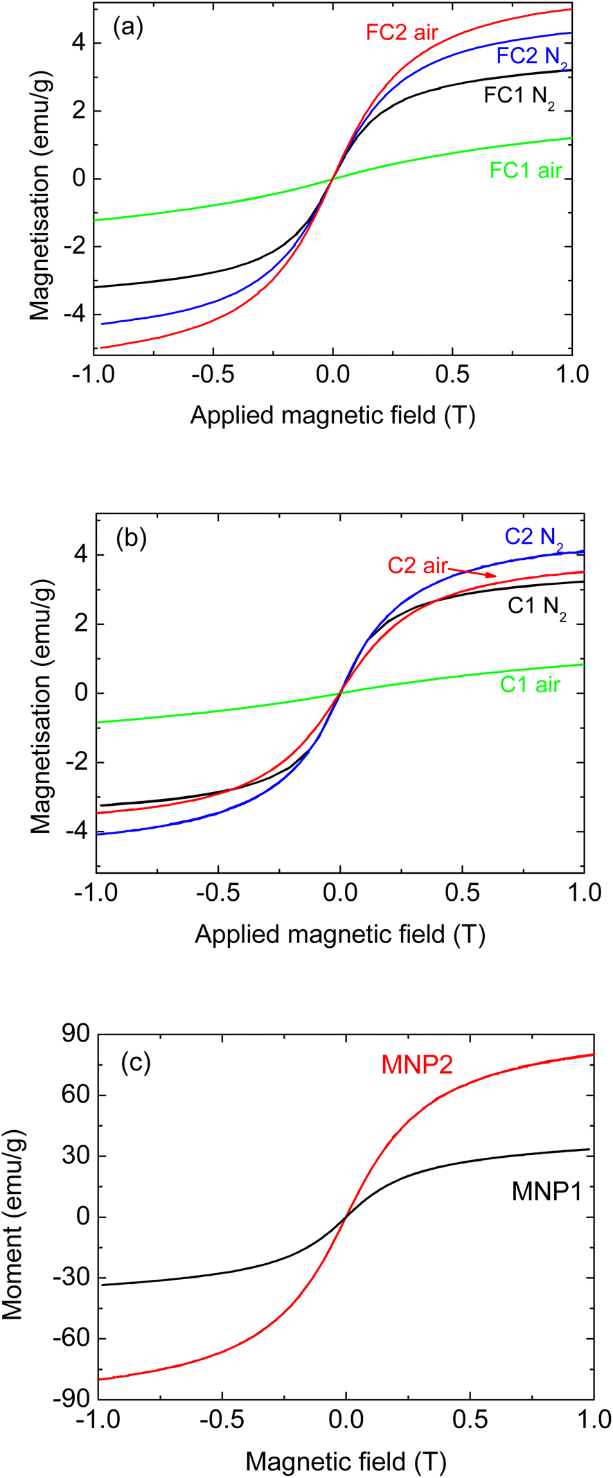 | ||
| Fig. 1 Magnetisation for composites prepared with MNP1 (6 nm ZnFe2O4) and MNP2 (6 nm Fe3O4), (a) with fine pyrolysed cork powder FC, (b) large pyrolysed cork powder C, and (c) MNPs alone. | ||
Considering the magnetisation curves of the MNPs alone (Fig. 1(c)), it can be seen that MNP2 shows a magnetisation almost three times greater than that of MNP1. This is in agreement with the literature, as magnetite is known to have a much greater magnetisation of around 90–100 emu g−1 (ref. 23, 24 and 26) compared to values around 30–35 emu g−1 for ZnFe2O4.22 It should be noted that the magnetisation has not saturated at the applied field of 1 T for any of these MNPs, so their maximum saturation magnetisation will be higher.
Regarding the composites, for both C and FC powders, the infiltration with MNP2 led to materials with higher magnetisation in comparison to MNP1, as would be expected. For FC powder (Fig. 1(a)), the FC2_air sample presents the highest magnetisation (about 5 emu g−1), with FC2_N2 being slightly lower and FC1_N2 slightly lower still (around 3 emu g−1). For the coarser C powder (Fig. 1(b)), the C2_N2 composite was the most magnetic one (about 4 emu g−1), and C2_air and C1_N2 had similar values (with C2_air being slightly higher), both over 3 emu g−1. Literature data have also shown that the nature and the properties of the actual MNPs have a significant effect on any composites produced.27 Nevertheless, considering that the magnetic oxide component does not exceed 18 wt% in any of these composites, they all have reasonable magnetisation for such composite materials. The exception to this was ZnFe2O4 (MNP1) when heated in air.
With both FC and C powders, MNP1 gave a composite material with a greatly reduced magnetisation when heated in air, with values around only 1 emu g−1, indicating a detrimental effect on the magnetic properties of these particular composites under these conditions.
Regarding the samples infiltrated with MNP1, as we have noted, the thermal treatment in air led to a significant decrease in the magnetisation; this change was observed for both C and FC powders. A possible explanation for this is that the reactive atmosphere caused a partial decomposition of the magnetic ZnFe2O4 phase. To verify if this was the case, Raman analyses were performed for samples FC1_N2 and FC1_air, to see if any difference in composition could be observed. As reported in Fig. 2(a), for both samples the signals characteristic of ZnFe2O4 are present; more specifically, peaks at 226, 291, 409, 495 and 613 cm−1 were detected.28–30 For the sample treated in air, however, additional signals can also be detected at 349 and 370 cm−1 (see the larger inset); this corresponds to lepidocrocite, a non-magnetic iron oxyhydroxide (γ-FeO(OH)).31 This confirms the hypothesis of a ZnFe2O4 reaction with oxygen, leading to lower overall magnetisation. This signal is not very intense; it has to be remembered, however, that Raman is not a quantitative technique and, therefore, the intensity of the peaks cannot be related to the actual proportion of each phase in a composite material. Indeed, the signal can be affected by several parameters, including the efficiency in scattering of the laser, as well as the crystallinity of the compound. In addition to these signals, peaks belonging to graphitic carbon can also be detected at 1325 and 1590 cm−1 (D and G peaks); these were previously observed in pyrolysed cork and derived materials.13,25
 | ||
| Fig. 2 (a) Raman spectra for samples FC1_N2 and FC1_air; (b) XRD pattern for the sample FC2_air. The standard XRD patterns used for identification were 75-2078 for α-graphite and 19-629 for magnetite. | ||
In Fig. 2(b), the XRD patterns for the sample FC2_air are reported; the clear diffraction pattern of magnetite (Fe3O4) can be seen, with the most intense peak at 2θ = 37.1°.32 From the relative intensities of the other peaks, no preferred orientation was observed. All peaks were quite wide, as expected from NPs of such small dimensions. A very wide, virtually amorphous peak corresponding to hexagonal α-graphite was also observed, centred around 26.6°, in agreement with the literature and as previously observed for pyrolysed cork powder.13
To study the morphology of the composites, SEM analyses were performed. Fig. 3 shows some images for the sample C2_air.
 | ||
| Fig. 3 SEM images for the sample C2_air at different magnifications. | ||
Fig. 3(a) (low magnification) shows the characteristic 3D structure of cork, with rectangular cells in the tangential axis, about 40 μm wide; this indicates that the cork morphology is preserved, despite the thermal treatment (pyrolysis and post-infiltration treatment). From the images taken at higher magnification (Fig. 3(b)–(d)), hexagonal cells about 15 μm in diameter (radial view) are apparent, and NPs can be observed on the surface of the cell wall, which are spherical particles with dimensions below 10 nm. Although in some cases aggregation of NPs occurs, the nanometric structure is preserved, without agglomeration at a micrometric scale. SEM images for other samples present similar features (data not shown).
These data confirmed that, once infiltrated in the pyrolysed cork powder, MNPs maintain their nanosized characteristics. The literature reports different behaviour for carbon–MNP composites. Kohzadi et al.,33 for instance, deposited iron oxide MNPs on graphene oxides, which were observed on the surface of the material, although with some aggregation. In the work of Fachina et al.,34 on the other hand, γ-CoFe2O4 MNPs were not seen on the graphene oxide surface, despite the composite showing magnetic behaviour. Similar results were obtained by Ruey-Shin et al.,35 as Fe3O4 MNPs were not clearly observed on the composite with activated carbon, probably due to their very small dimensions.
As can be seen in Table 5, all the composites and the carbonised cork alone (C and FC) had negative zeta potentials, showing that these particles dispersed in water had a negative charge. Generally, a suspension with a zeta potential of ±20 mV or more is considered a stable one, and if over ±30 mV, it is very stable. The zeta potentials of the large (C) and fine (FC) pyrolysed cork particles alone are high, indicating very good stability, at −20.5 mV and −36.2 mV, respectively. The least stable composite suspensions were FC1_air (6 nm ZnFe2O4) and three of the suspensions made with 15 nm Fe3O4 (MNP4): C4_N2, FC4_N2 and FC4_air , and those made using the fine cork powder (FC) had the lowest zeta potentials of all (−6.6 mV and −7.1 mV for FC4_N2 and FC4_air, respectively). C4_air, also made using 15 nm Fe3O4 (MNP4) in air with the large carbonised cork particles, was stable, however.
| Sample name | Description | Zeta potential (mV) |
|---|---|---|
| C | Large pyrolysed cork powder | −20.5 ± 2.2 |
| C1_air | ZnFe2O4, 6 nm, air | −22.7 ± 2.8 |
| C2_air | Fe3O4, 6 nm, air | −48.2 ± 0.8 |
| C3_air | Fe3O4, 9 nm, air | −33.8 ± 1.2 |
| C4_air | Fe3O4, 15 nm, air | −22.7 ± 0.1 |
| C1_N2 | ZnFe2O4, 6 nm, N2 | −24.1 ± 0.9 |
| C2_N2 | Fe3O4, 6 nm, N2 | −36.9 ± 1.5 |
| C3_N2 | Fe3O4, 9 nm, N2 | −28.7 ± 0.3 |
| C4_N2 | Fe3O4, 15 nm, N2 | −10.2 ± 1.0 |
| FC | Fine pyrolysed cork powder | −36.2 ± 3.1 |
| FC1_air | ZnFe2O4, 6 nm, air | −10.4 ± 1.6 |
| FC2_air | Fe3O4, 6 nm, air | −56.3 ± 2.8 |
| FC3_air | Fe3O4, 9 nm, air | −34.1 ± 0.5 |
| FC4_air | Fe3O4, 15 nm, air | −7.1 ± 0.9 |
| FC1_N2 | ZnFe2O4, 6 nm, N2 | −12.1 ± 0.5 |
| FC2_N2 | Fe3O4, 6 nm, N2 | −34.4 ± 2.9 |
| FC3_N2 | Fe3O4, 9 nm, N2 | −25.2 ± 3.9 |
| FC4_N2 | Fe3O4, 15 nm, N2 | −6.6 ± 0.8 |
In general, the composites made with 6 nm ZnFe2O4 (C1/FC1, using MNP1) were always less stable than those made with 6 and 9 nm Fe3O4 (C2/FC2 and C3/FC3, using MNP2 and MNP3) under the same conditions, and this appeared worse for MNP1 when the fine cork powder (FC) was used. The smallest 6 nm Fe3O4 (C2 using MNP2) consistently gave the highest zeta potential for all composition series, with the larger 9 nm Fe3O4 (C3 using MNP3) made by the same route consistently being the second best. The composites made using the small MNP2 and MNP3 NPs appeared more stable in suspension when the fine cork (FC) was used and were worse when heated under N2. Conversely, for MNP1 and MNP2, the use of fine cork powder (FC) resulted in less stable suspensions with much lower zeta potentials. Overall, MNP2 heated in air gave the highest zeta potentials of −48.3 mV and −56.3 mV for C2_air and FC2_air, respectively.
3.2 Effect of MNP size: Fe3O4 with different dimensions
Considering the results described in the previous section, further infiltration tests were carried out. As the zinc ferrite-based materials showed the worst performance, they were not used for other experiments; therefore, the work was focused on the use of magnetite MNPs with different dimensions, as reported in Table 1. Indeed, MNPs with diameters of 9 and 15 nm were also used; this was done to see which MNPs were more effectively infiltrated and the consequent effect on the magnetisation of the composites. It is known that the measured magnetisation of nanoparticles is generally greater with larger size as they approach or exceed the magnetic domain size. Although these particles are larger, these dimensions are still much smaller than the pores of the walls of the cork cells, estimated to be just below 100 nm.12 They are also all superparamagnetic. As with the previous experiments, post-infiltration treatments in either N2 or air were considered.Fig. 4 shows the magnetisation of the composites, as well as of the simple MNPs.
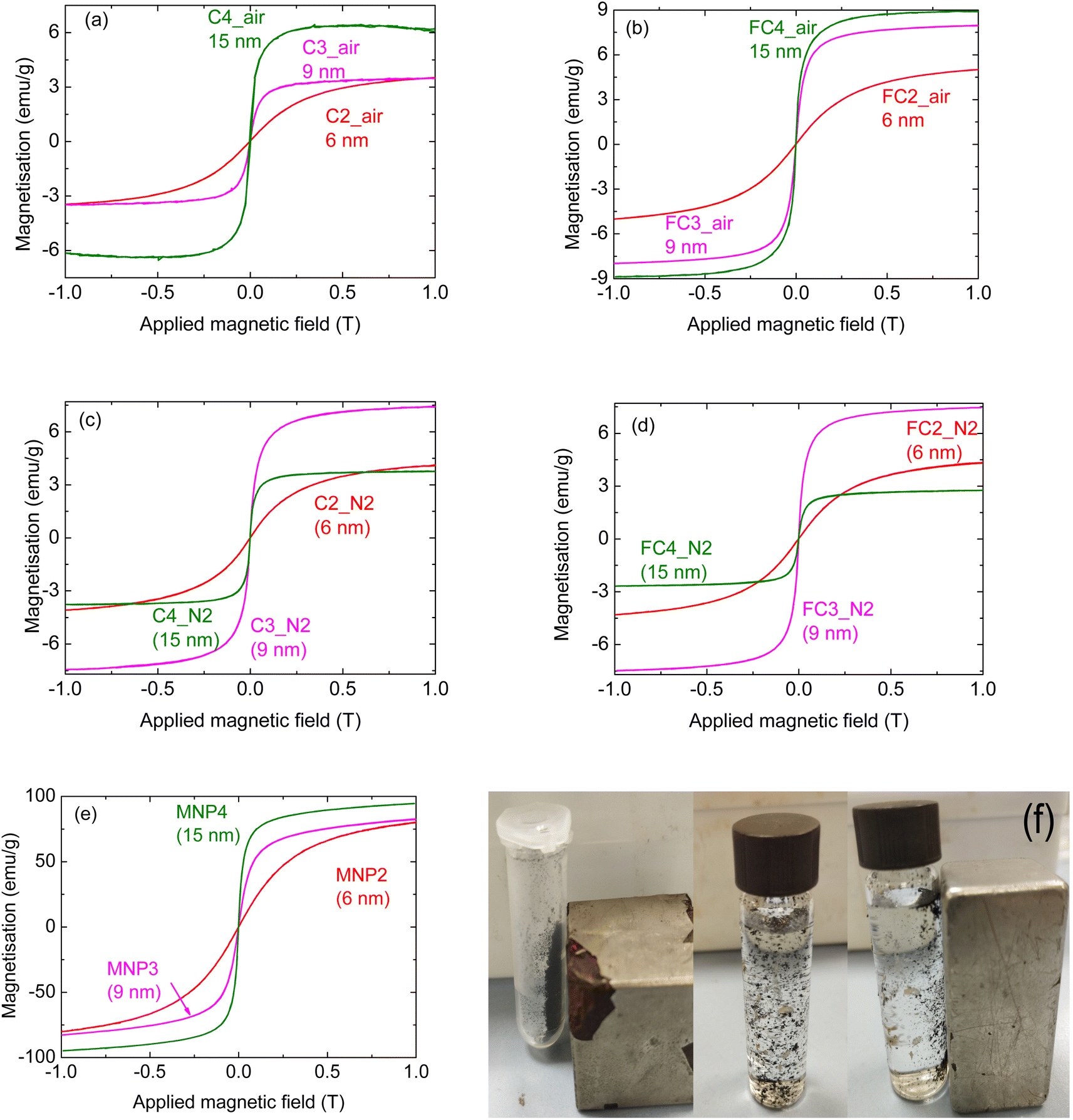 | ||
| Fig. 4 Magnetisation of the composites prepared with Fe3O4 MNPs of different dimensions, using pyrolysed large cork powder C (a) in air and (c) in N2; pyrolysed fine cork powder FC (b) in air and (d) in N2; (e) MNPs alone. (f) Photographs of FC4_air particles in air and in a suspension of water, without and with the presence of an exterior magnet, demonstrating that this material can be magnetically separated. | ||
Considering the samples treated in air (Fig. 4(a) and (b) for larger and finer cork powder, respectively), it can be seen that the highest magnetisation was measured for samples infiltrated with the largest MNPs (15 nm), i.e.C4_air and FC4_air. This is in line with the properties of the MNPs themselves, as shown in Fig. 4(e), where the magnetization approaches 100 emu g−1 in the case of MNP4. More specifically, considering the infiltrations performed on the fine cork-derived powder, it can be seen that the measured magnetisation for FC3_air and FC4_air is significantly higher than for FC2_air (Fig. 4(b)); moreover, the curves are steeper and approach the maximum obtained at up to 1 T more quickly. The shape of the curves is in agreement with those of the pure MNPs (see Fig. 4(e)); this indicates that the magnetic behaviour of the different MNPs is maintained when they are incorporated into the matrix, and all are still superparamagnetic. Considering the values of the infiltrated inorganic phase as a function of the MNP dimensions (Fig. 5(a)), it can be seen that the most effective infiltrations were performed with MNPs of an intermediate size of 9 nm; with these particles, in fact, the FC3_air composites consisted of 17% wt of inorganic compounds, compared to 12 and 11% wt of the 6 and 15 nm particles, respectively. However, despite the higher proportion of the magnetic phase, the FC3_air composite reaches a lower magnetisation value, due to the lower MNP3 magnetic properties.
 | ||
| Fig. 5 Inorganic phase residues as a function of the MNPs' dimensions for composites prepared (a) in air and (b) in N2. | ||
Regarding the samples prepared with the larger cork-derived powder, the same magnetisation value is achieved for samples C2_air and C3_air (about 3.5 emu g−1); the shape of the curves, however, is different, due to the different magnetic behaviour of the infiltrated MNPs. When larger particles are employed (sample C4_air), a measured magnetisation greater than 6 emu g−1 was reached; although it is higher than values obtained with the smaller MNPs, it is still significantly lower than that for the sample FC4_air (almost 9 emu g−1). This indicates a better performance for the composites prepared with the finer pyrolysed cork powder. Indeed, from Fig. 4(f), it can be seen that in the presence of a magnet, the powder is attracted towards it, confirming its magnetisation. This is also the case when suspended in water, allowing for the magnetic extraction of these composite particles and demonstrating that these magnetisation values are sufficient for such applications.
The same magnetisation for the composites prepared with the fine powder was also measured when smaller MNPs were employed (Fig. 4(b)). These data can be partially explained considering the greater quantity of inorganic phase infiltrated in the fine powder (see Fig. 5(a)); indeed, in samples C2_air and C3_air, an oxide proportion of 3 and 12% wt was measured, vs. 13 and 17% wt in FC2_air and FC3_air.
These lower concentrations, however, cannot be the only cause of the difference in magnetisation. Previous studies on similar composites (i.e. graphitic carbon with MNPs) showed that the magnetic properties may be affected by several parameters, including the characteristics of the carbon-based substrate,33 although the effect of each parameter is not always understood.
When the infiltrated materials were thermally treated in N2, however, a different behaviour was observed. Samples prepared with MNP2 and MNP3 showed a pattern similar to that observed in the samples prepared in air, i.e. an increase in the magnetisation with increasing particles' dimensions; this was seen for composites prepared with both large and fine powders. When the 15 nm particles were used, however, a significant decrease in the measured magnetisation was seen; indeed, the sample C4_N2 reaches a maximum value of about 3 emu g−1, comparable to that of C2_N2 (where 6 nm particles were employed). For the sample prepared with the fine cork pyrolysed powder, this feature is even more obvious, as the maximum measured magnetisation of FC4_N2 is even lower than that of FC2_N2. These data cannot be easily explained, and it is not clear why such a decrease was observed; however, the fact that the same behaviour is observed with these particles with both large and fine pyrolysed cork powders indicates a consistency and, hence, a common origin for the effect (i.e. not a measurement artifact).
It has to be highlighted that the magnetisation curves for C4_N2 and FC4_N2, although less intense, still show a very steep initial rise in the signal; this indicates that the nature of the magnetic MNP does not change, but it is more likely that, for some reason, fewer MNPs are present. A hypothesis is that the more reducing (oxygen-free) N2 atmosphere led to changes in the oxidation state in some of the iron ions, forming non-magnetic, or lesser-magnetic, compounds; analysis of the samples did not show any significant difference in the composition in comparison to other samples (data not shown). It is possible, however, that small changes in the composition and/or oxidation state on the surface of these small NPs, not detected by analytical techniques such as Raman or XRD, may have a significant effect on magnetic properties.
Some magnetite (Fe3O4) may have been converted to the less magnetic wustite phase (FeO); bulk FeO is paramagnetic, and NPs of FeO have been reported to have a mass magnetisation of only around 11 emu g−1.36 It has been shown that magnetite can be reduced to FeO with heating in the presence of carbon37 and in carbon nanotube nanoreactors.38 In our case, the samples were heated with a large amount of extremely porous carbon present under nitrogen. Furthermore, impurities such as carbon can occupy crystal interstices of magnetite to promote FeO formation above 156 °C, preventing any formed FeO from redissolving into the solid solution of magnetite.39 This would occur on the surface of the magnetite NPs, where the reaction rate for the reduction of Fe3O4 to FeO has been found to be controlled by the phase boundary,40 but no such species were detected by XRD or Raman analysis. However, deficient Fe1−xO can also form in spinel-like “Koch-Cohen” clusters mixed with Fe3O4,36,41 meaning that it may also be extremely difficult to detect such a phase. Further investigation is needed to better understand this, but it seems possible that under reducing conditions in the presence of carbon, some decomposition of magnetite to FeO or other species could have occurred, resulting in a reduced measurable magnetisation. It should also be noted that C4_N2 and FC4_N2 also had two of the lowest zeta potential values (−10.2 and −6.6 mV, respectively), perhaps indicating that these secondary iron oxide phases also incurred a degree of instability in their aqueous suspensions.
Based on these data, it can be concluded that the post-infiltration treatment is more effective when performed in air than in N2.
C4_air and FC4_air were chosen for surface area measurements as they were the best performing ones in terms of magnetic properties (see Fig. 6); it should also to be highlighted that the SSA should not significantly differ considering different nanoparticles, as it is mostly determined by the microstructure and morphology of the carbonised cork. The BET SSA of FC_4 made with the fine cork powder (36.12 m2 g−1) was approximately 10 times greater than that of C_4 made with the large cork powder (3.18 m2 g−1). This is not surprising, as FC_4 is synthesised from much smaller cork particles than C_4, the range of dimensions of C (200–400 μm) being 10 times greater than those of FC (20–40 μm). The t-plot data indicate that for FC_4, the surface accounted for 21.68 m2 g−1 and microporosity (<2 nm diameter) for 14.43 m2 g−1. It was not possible to extract reliable t-plot data for the much lower SSA C_4. This lower SSA of C_4 may also help explain why FC_4 shows consistently higher magnetisation than C_4 (except under N2, where decomposition into FeO is a more important factor), as FC_4 has a greater SSA for more MNPs to adhere to. The N2 adsorption/desorption isotherms of C_4 and FC_4 are shown in Fig. 6(a) and (b). Both have a type V isotherm, where the adsorbent–adsorbate interaction is weak, but this type is often obtained with porous adsorbents. Lateral interactions between adsorbed molecules are strong in comparison to interactions between the adsorbent surface and adsorbate, and BET analysis is inherently less reliable for this type. There is no inflection point, indicating that this is probably all monolayer coverage, with capillary condensation then occurring in mesopores to form the hysteresis loop. FC_4 has a hysteresis that seems to be between types H3 and H4; H3 is caused by assemblage of plate-like particles forming slit-like pores, while H4 is caused by narrow slit-like pores or particles with internal voids of irregular shape and broad size distribution. C_4 shows more like type H3 hysteresis, but both clearly have very similar morphology and surface chemistry, resulting in similar interactions with N2, despite the great difference in SSAs.
 | ||
| Fig. 6 Specific surface area (SSA) measurements of C_4 (a, c and e) and FC_4 (b, d and f). BET N2 adsorption/desorption isotherms (a and b), and BJH average pore radius distribution for pore area (c and d) and pore volume (e and f) below 100 Å. | ||
The BJH method was used to analyse the distribution of pores below 100 Å radius, where microporosity = <20 Å diameter (<10 Å radius), mesoporosity = 20–500 Å diameter (10–250 Å radius), and macroporosity = >500 Å diameter (>250 Å radius). It is immediately apparent that the pore size distributions for FC_4 and C_4 below a 100 Å radius are very similar, which is not surprising, as they are essentially the same material, with similar mesoporosity, but with a significant difference in particle size and, hence, SSA. Both showed a steadily increasing cumulative pore area (Fig. 6(c) and (d)) and pore volume (Fig. 6(e) and (f)) as the average pore radius decreased from 85 to 20 Å (= pore diameters from 170 to 40 Å). As would be expected, the pore area was dominated by the contribution of smaller pores (peaking at around 25 Å radius = 50 Å diameter, in the mesopore range); however, even though there were fewer large pores, they contributed more to the total pore volume, with a peak contribution at around 75 Å radius (=150 Å diameter) and remaining significant down to around 40 Å for both FC_4 and C_4. These relate to the small sub-100 nm pores that are present in the walls of the cork cells,12 and that become even smaller through contraction as the cork wood is carbonised. Therefore, it can clearly be seen that although they differ greatly in SSAs, the pore structures of FC and C are almost identical, with the main contribution to this small-scale porosity (as opposed to the large hexagonal cells) being from pores in the mesopore range.
Comparing these magnetic data with the literature for other carbon–MNP composites, it can be seen that higher magnetisation values were obtained when graphene oxide was used for carbon-based materials; Fachina,34 for instance, reported magnetisation values slightly higher than the highest one observed in this work (12 vs. 9 emu g−1), while Kohzadi33 reported even higher values. It should be remembered, however, that graphene oxide synthesis is less environmentally friendly, with a higher impact on the environment and, hence, is not ideal for materials aimed at environmental remediation.
When activated carbon or graphitic carbon from natural sources was used, on the other hand, smaller magnetisation values were registered. Ruey-Shin et al.,35 for instance, measured a magnetisation of about 6 emu g−1 for a composite based on activated carbon. Vynaygam et al.42 employed carbon derived from rubber fig tree leaves, and their composite showed magnetisation values lower than 1 emu g−1.
The higher values obtained in this study confirm the potential of carbon derived from cork to be decorated with MNPs to become effective functional materials. One of the reasons for these encouraging results may be the very high porosity of cork, which leads to porous graphitic carbon that can be effectively modified with MNPs.
3.3 Infiltration with different amounts of Fe3O4
Additional experiments were performed using pyrolysed cork fine powders (FC). More specifically, MNP4 was employed for infiltration with different concentrations, i.e. different C:Fe ratios; this was done to see whether the quantity of MNPs in solution had an effect on the amount infiltrated into the composite, and on the resulting magnetic properties. As stated in the experimental section, three concentrations were used, namely C:Fe ratios of 138, 69 and 40, corresponding to samples FC4_a, FC4_b and FC4_c, respectively (see Table 3). Fig. 7 shows the magnetisation curves for the three different samples.
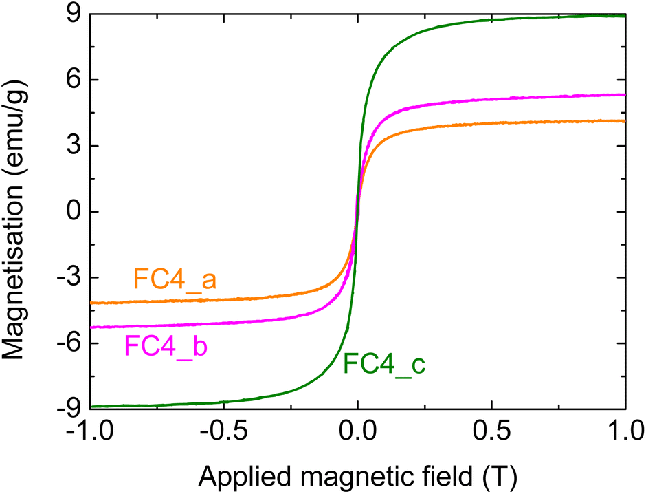 | ||
| Fig. 7 Magnetisation of composites prepared using different MNP4 concentrations; more specifically, C:Fe ratios of (a) 138, (b) 69, and (c) 40. | ||
It can be seen that, as expected, there is an increase in the measured magnetisation for greater Fe concentrations in the suspensions employed for the infiltrations; the increase, however, is not linear. The magnetisation, in fact, goes from about 4 to over 5 emu g−1 when doubling the initial MNP4 concentration in the infiltration suspension; a much greater increase, however, is observed with a higher MNP content, reaching a value of almost 9 emu g−1 (note: this last sample FC_c was prepared under the same conditions as FC4_air, shown above). These data confirm that the magnetic properties of the composites can be tailored by changing the infiltration conditions.
3.4 Stability of the composites
The composites were tested in a liquid environment, to see whether the MNPs were anchored to the graphitic carbon and were not dissolved. Two solvents were considered, H2O and chloroform (see Table 4); they were chosen considering the possible applications of the materials for wastewater treatment. In fact, the removal of pollutants from aqueous environments requires stability in water; chloroform, on the other hand, can be considered a model molecule for oil–water separation [Turco, 2024].7Fig. 8 shows the results for samples prepared with all three different MNPs; the value of the magnetisation was normalised to that of the untreated sample for each MNP to make the comparison easier. Samples infiltrated with MNPs of 6 and 9 nm show a similar behaviour; in fact, in both cases there is a significant decrease in the magnetisation after the chloroform treatment – about three times lower for FC2 and half of the original value for FC3. A much smaller decrease was measured when these samples were treated in water; in this case, the magnetisation was between 75 and 80% of the value for the untreated corresponding composites (Fig. 8(a) and (b), respectively). This shows their relative stability in an aqueous environment, and Fig. 4(f) demonstrates that they can be removed magnetically from a suspension. For the sample FC_4, on the other hand, a different behaviour was observed; both FC4_W and FC4_Cl, in fact, show a small decrease in the magnetisation with increasing applied magnetic field above ∼0.25 T (Fig. 8(c)). Such a decrease normally indicates the presence of a diamagnetic phase in the material.43,44 As this behaviour was not observed prior to the solvent treatment, it is reasonable to think that some changes took place during such treatment.
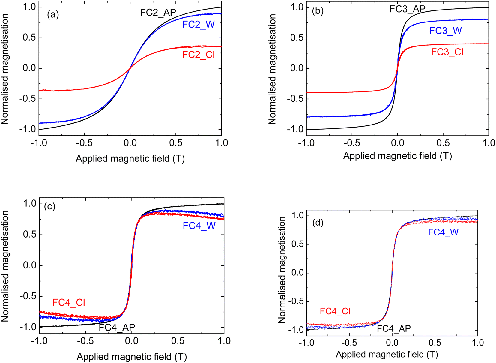 | ||
| Fig. 8 Stability of the composites prepared using pyrolysed fine cork powder and (a) MNP2, (b) MNP3, and (c) MNP4, (d) MNP4 after diamagnetic component subtraction. The curves indicated with AP, W and Cl correspond to the material as prepared, and left in water and in chloroform, respectively, for 24 hours. | ||
Despite the fact that superparamagnetic iron oxide NPs at or below the single domain size should have measurable magnetisation close to the maximum, this is often seen not to be the case for NPs of 15 nm or less. This has been attributed to various causes such as surface demagnetisation effects becoming more important on such small particles and the formation of diamagnetic α-Fe2O3 on the surface,45 variations in crystallinity and surface roughness46 and surface spin disorder.47,48 Indeed, a study by Nedelkoski et al.,46 which included MNPs made by the same methods as those used here to make MNP4,24 indicated another possible cause for such effects. They showed that strong antiferromagnetic super-exchange interactions across antiphase domain boundaries can significantly decrease the magnetisation due to the formation of multiple magnetic domains near the surface, even in NPs below 15 nm, creating a surface anisotropy, which would reduce overall magnetisation as a field is applied. If this is the case, an interaction of the MNP surface with the solvent (water or chloroform) appears to have encouraged the growth of surface antiphase domain boundaries.
A combination of these effects could explain the anomalous magnetic behaviour after treatment in solution. To perform a proper comparison with the FC4_AP sample, the diamagnetic component of the signal was subtracted, following the standard literature protocol;43,49 the corrected curves are reported in Fig. 8(d). It can be seen that the change in the magnetisation after the solvent treatment is almost negligible (within the experimental error) with both water and chloroform. It also needs to be pointed out that, while this anomalous reduction in magnetisation is of academic interest, it has no significant effect on the proposed application for these materials. It will not affect their adsorption capabilities for pollutants, and the magnetisation is still more than sufficient for magnetic separation and removal of the powders, as shown in Fig. 4(f).
Overall, these data indicate that the stability of the composites improves with an increase in the dimensions of the MNPs and such improvement is particularly significant in chloroform; this latter feature makes the use of the larger MNPs more suitable for oil–water separation applications.
4. Conclusions
The preparation of magnetic graphite composites from pyrolysed sustainable cork waste powder was successfully achieved. This is the first time that magnetic carbon–MNP composites have been made from pyrolysed/carbonised cork, resulting in a carbon material that retained the porous microstructure of the original cork, ideal for the absorption of pollutants or separation of oils and water, while also being magnetically separable afterwards. Two sizes of waste cork powder were studied, and the fine cork powder (20–40 μm) allowed for a better impregnation of the NPs into the pyrolysed cork, giving a superior level of magnetisation in the composite, than coarse cork powder (200–400 μm). It was also shown that heating in air was better than nitrogen post-infiltration, with the nitrogen atmosphere possibly reducing magnetite to form partial FeO with a concurrent reduction in magnetic capabilities. Indeed, the cork-derived graphite powder was modified with MNPs with different chemical compositions and dimensions (from 6 to 15 nm); moreover, different MNP concentrations in the composites led to different magnetisation values, up to 9 emu g−1 for 15 nm Fe3O4 NPs that accounted for only around 12 wt% of the composite. Stability studies showed that composites prepared with the largest 15 nm MNPs were also the most stable in both aqueous and organic solvents, making them suitable for applications in environmental remediation. Based on this, as future work, these composites will be tested for the removal of pollutants in simulated wastewater and oil–water separation processes. Although the scale-up of the process is beyond the scope of this preliminary work, it should be highlighted that the method involves simple steps that should be replicable on a larger scale.Data availability
The authors declare that the data supporting this article have been included as part of the ESI†.Conflicts of interest
The authors declare that they have no conflict of interest.Acknowledgements
Clara Piccirillo, Francesca Scalera and Alessandra Quarta would like to thank the Italian Ministry of Research (MUR) for supporting this work through the complementary actions to the NRRP “Fit4MedRob” Grant (PNC0000007, CUP B53C22006960001). R. C. Pullar wishes to acknowledge the support of the project HYPERMAG, “HYbrid ferrite nanocomposites for novel Rare-earth free PERmanent MAGnets”, which received funding from the European Union Next-Generation EU – National Recovery and Resilience Plan (NRRP) – MISSION 4 COMPONENT 2, INVESTIMENT 1.1 Fondo per il Programma Nazionale di Ricerca e Progetti di Rilevante Interesse Nazionale (PRIN) project No. P2022RRRT4, CUP H53D23007990001. Anna Grazia Monteduro and Giuseppe Maruccio would like to thank the ISABEL project (UE-H2020-INFRADEV-2018-2020, Grant No. 871106). Annalisa Caputo would like to thank the “Tecnopolo per la medicina di precisione” (TecnoMed Puglia)–Regione Puglia: DGR n.2117 del 21/11/2018 (CUP: B84I18000540002), and “Tecnopolo di Nanotecnologia e Fotonica perla medicina di precisione” (TECNOMED)–FISR/MIUR-CNR: delibera CIPE n. 3449 del 7–08–2017 (CUP: B83B17000010001).References
- S. Farissi, S. Zakkaria, K. A. Akhilghosh, T. Prasanthi, A. Muthukumar and M. Muthuchamy, Electrooxidation of amoxiccil in aqueous solution with graphite electrodes: Optimisation of degradation and deciphering of byproducts using HRMS, Chemosphere, 2023, 345, 140415 Search PubMed.
- S. M. Mousavi, S. A. Hashemi, M. Y. Kalashgrani, A. Gholami, M. Binazadeh, W. H. Chiang and M. M. Rahman, Recent advances in energy storage with graphene oxide for supercapacitor technology, Sustainable Energy Fuels, 2023, 7, 5176–5197 RSC.
- J. Zhang, S. Qiu and F. Deng, Oxygen-doped carbon nanotubes with dual active cites to enhance ·OH formation through three electron oxygen reduction, J. Hazard. Mater., 2022, 465, 133261 CrossRef PubMed.
- M. H. Saleem, M. F. B. Mfarrej, K. A. Khan and S. A. Alharthy, Emerging trends in wastewater treatment: Addressing microorganic pollutants and environmental impact, Sci. Total Environ., 2024, 913, 169755 CrossRef CAS PubMed.
- S. Rajagopalan, R. D. Brook, P. R. V. O. Salerno, B. Bourges-Sevenier, P. Landrigan, M. J. Nieuwenhuijsen, T. Munzel, S. Deo and S. Al-Kindi, Air pollution exposure and cardiometabolic risk, Lancet Diabetes Endocrinol., 2024, 12, 196–208 CrossRef CAS PubMed.
- S. S. A. Alkurdi, I. Herath, J. Bundschuh, R. A. Al Juboori, M. Vithanage and D. Mohan, Biochar versus bone char for a sustainable inorganic arsenic mitigation in water: What needs to be done in future research?, Environ. Int., 2019, 127, 52–69 CrossRef CAS PubMed.
- A. Turco, A. Foscarini, C. Piccirillo, E. Primiceri, M. S. Chiriacò and F. Ferrara, A Promising Solution for Water Remediation: PDMS-(Nano)carbon Hybrid Materials for Oil Removal, Appl. Mater. Today, 2024, 38, 1020218 Search PubMed.
- A. Khosravi, A. Zarepour, R. S. Varma and A. Zarrabi, Sustainable synthesis: natural processes shaping the nanocircular economy, Environ. Sci.:Nano, 2024, 11, 688–707 RSC.
- R. A. Omar, N. Talreja, D. Chuhan and M. Ashfaq, Waste-derived carbon nanostructures (WD-CNs): An innovative step towards waste to treasury, Environ. Res., 2024, 246, 11806 CrossRef PubMed.
- M. N. H. Sani, M. Amin, A. B. Siddique, S. O. Nasif, B. B. Ghaley, L. Ge, F. Wang and J. W. H. Yong, Waste-derived nanobiochar: A new avenue towards sustainable agriculture, environment, and circular economy, Sci. Total Environ., 2023, 905, 166881 CrossRef CAS PubMed.
- Q. Wang, C. Luo, Z. Lai, S. Chen, D. He and J. Mu, Honeycomb-like cork activated carbon with ultra-high adsorption capacity for anionic, cationic and mixed dye: Preparation, performance and mechanism, Bioresour. Technol., 2022, 357, 127363 CrossRef CAS PubMed.
- H. Pereira, The rationale behind cork properties: a review of structure and chemistry, BioResources, 2015, 10, 1–23 Search PubMed.
- R. C. Pullar, R. M. Novais, A. P. F. Caetano, K. A. Krishnakumar and K. P. Surendran, Ultra-light-weight microwave X-band EMI shielding or RAM material made from sustainable pyrolysed cork templates, Nanoscale, 2023, 15, 15982 RSC.
- F. Scalera, A. G. Monteduro, G. Maruccio, L. Blasi, F. Gervaso, E. Mazzotta, C. Malitesta and C. Piccirillo, Sustainable chitosan-based electrical responsive scaffolds for tissue engineering applications, Sustainable Mater. Technol., 2021, 28, e00260 CrossRef CAS.
- R. C. Pullar, P. Marques, J. Amaral and J. A. Labrincha, Magnetic wood-based biomorphic Sr3Co2Fe24O41 Z-type hexaferrite ecoceramics made from cork templates, Mater. Des., 2015, 82, 297–303 CrossRef CAS.
- R. C. Pullar, A. Accaries, D. H. G. Scheffer, A. P. F. Caetano and R. M. Novais, Cork derived TiO2 biomorphic ecoceramics, Open Ceram., 2022, 9, 100243 CrossRef CAS.
- F. Scalera, L. Carbone, S. Bettini, R. C. Pullar and C. Piccirillo, Biomimetic calcium carbonate with hierarchical porosity produced using cork as a sustainable template agent, J. Environ. Chem. Eng., 2020, 8, 103594 CrossRef CAS.
- R. Li, X. Shen, J. Zhang, Q. Jiang, L. Wang and Y. Zhang, Tailoring biochar supported iron nanoparticles to activate persulfate for atrazine degradation in soil, Chem. Eng. J., 2024, 479, 147662 CrossRef.
- Y. Wang, S. Xu, Q. Wang, K. Hu, H. Zhang, J. Chang, N. Liu, K. Oh and H. Cheng, Tetracycline removal from aqueous solution by magnetic biochar modified with different iron valences: A comparative study, Sep. Purif. Technol., 2024, 339, 126614 CrossRef CAS.
- H. Liang, C. Zhu, A. Wang and F. Chen, Facile preparation of NiFe2O4/biochar composite adsorbent for efficient adsorption removal of antibiotics in water, Carbon Res., 2024, 3, 2 CrossRef CAS.
- A. Baye, H. Bandal and H. Kim, FeCx-coated biochar nanosheets as efficient bifunctional catalyst for electrochemical detection and reduction of 4-nitrophenol, Environ. Res., 2024, 26, 118071 CrossRef PubMed.
- Y. Lin, W. Yao, Y. Cheng, H. Qian, X. Wang, Y. Ding, W. Wu and X. Jiang, Multifold enhanced T2 relaxation of ZnFe2O4 nanoparticles by jamming them inside chitosan nanospheres, J. Mater. Chem., 2012, 22, 5684–5693 RSC.
- J. Park, E. Lee, N. M. Hwang, M. Kang, S. C. Kim, Y. Hwang, J. G. Park, N. J. Noh, J. Y. Kim, J. H. Park and T. Hyeon, One-nanometer-scale size-controlled synthesis of monodisperse magnetic iron oxide nanoparticles, Angew. Chem., 2005, 44, 2872–2879 CrossRef CAS PubMed.
- W. W. Yu, J. C. Falkner, C. T. Yavuz and V. L. Colvin, Synthesis of monodisperse iron oxide nanocrystals by thermal decomposition of iron carboxylate salts, Chem. Commun., 2004, 2306–2307 RSC.
- A. Quarta, R. M. Novais, S. Bettini, M. Iafisco, R. C. Pullar and C. Piccirillo, A sustainable multi-function biomorphic material for pollution remediation or UV absorption: aerosol assisted preparation of highly porous ZnO-based materials from cork templates, J. Environ. Chem. Eng., 2019, 8, 102936 CrossRef.
- R. M. Cornell and U. Schwertmann, The Iron Oxides: Structures, Properties, Reaction, Occurences and Uses, Wiley, 2nd edn, 2006 Search PubMed.
- S. Gyergyek, E. Chernyshova, K. Böór, M. Necemer and D. Makovec, Magnetic carbon nanocomposites via the graphitization of glucose and their induction heating, J. Alloys Compd., 2023, 953, 170139 CrossRef CAS.
- D. Neravathu, A. R. Paloly, P. Sanjan, M. Satheesh and M. J. Bushiri, Hybrid nanomaterials of ZnFe2O4/α-Fe2O3 implanted graphene for electrochemical glucose sensing applications, Diamond Relat. Mater., 2020, 106, 107852 CrossRef CAS.
- B. Hangai, E. Borsari, E. C. Aguiar, G. G. Garcia, E. Longo and A. Z. Simões, Superparamagnetic behaviour of zinc ferrite obtained by the microwave assisted method, J. Mater. Sci.:Mater. Electron., 2017, 28, 10772–10779 CrossRef CAS.
- B. Paz-Díaz, A. R. Vázquez-Olmos, A. Almaguer-Flores, V. L. García-Pérez, R. Y. Sato-Berrú, Y. C. Almanza-Arjona and V. Garibay-Febles, ZnFe2O4 and CuFe2O4 nanocrystals: Synthesis, characterization, and bactericidal application, J. Cluster Sci., 2023, 34, 111–119 CrossRef.
- S. Mahadevan, G. Gnanaprakash, J. Philip, B. P. C. Rao and T. Jayakumar, X-ray diffraction-based characterization of magnetite nanoparticles in presence of goethite and correlation with magnetic properties, Phys. E, 2007, 39, 20–25 CrossRef CAS.
- S. Li and L. Hihara, A micro-Raman spectroscopic study of marine atmospheric corrosion of carbon steel: The effect of akageneite, J. Electrochem. Soc., 2015, 162, C495–C502 CrossRef CAS.
- S. Kohzadi, N. Najmoddin, H. Baharifar and M. Shabani, Functionalized SPION immobilized on graphene-oxide: Anticancer and antiviral study, Diamond Relat. Mater., 2022, 127, 109149 CrossRef CAS PubMed.
- Y. J. Fachina, M. B. de Andrade, A. C. S. Guerra, T. R. T. dos Santos, R. Bergamasco and A. M. S. Vieira, Graphene oxide functionalized with cobalt ferrites applied to the removal of bisphenol A: ionic study, reuse capacity and desorption kinetics, Environ. Technol., 2022, 43, 1388–1404 CrossRef CAS PubMed.
- J. Ruey-Shin, Y. Yao-Chung, L. Chien-Shiun, L. Kuen-Song, L. His-Chuan, W. Sea-Fue and S. An-Cheng, Synthesis of magnetic Fe3O4/activated carbon nanocomposites with high surface area as recoverable adsorbents, J. Taiwan Inst. Chem. Eng., 2018, 90, 51–60 CrossRef.
- M. Gheisari, M. Mozaffari, M. Acet and J. Amighian, Preparation and investigation of magnetic properties of wüstite nanoparticles, J. Magn. Magn. Mater., 2008, 320, 2618–2621 CrossRef CAS.
- K. Ishizaki and K. Nagata, Microwave Induced Solid–Solid Reactions between Fe3O4 and Carbon Black Powders, ISIJ Int., 2008, 48, 1159 CrossRef CAS.
- F. Cao, K. Zhong, A. Gao, C. Chen, Q. Li and Q. Chen, Reducing Reaction of Fe3O4 in Nanoscopic Reactors of a-CNTs, J. Phys. Chem. B, 2007, 111, 1724–1728 CrossRef CAS PubMed.
- W. Zhang, Z. Xue, Z. Zou and H. Saxén, The Ideal and Regular Mechanisms of Hematite Reduction Reactions, Cryst. Res. Technol., 2022, 57, 2100240 CrossRef CAS.
- K. He, Z. Zheng and Z. Chen, Multistep reduction kinetics of Fe3O4 to Fe with CO in a micro fluidized bed reaction analyzer, Powder Technol., 2020, 360, 1227–1236 CrossRef CAS.
- F. Koch and J. B. Cohen, The defect structure of Fe1-xO, Acta Crystallogr., Sect. B, 1969, 25, 275 CrossRef CAS.
- R. Vinaygam, M. Quadras, T. Varadavenkatesan, D. Debraj, L. C. Goveas, A. Samanth, D. Balakrishnan and R. Selvaraj, Magnetic activated carbon synthetized using rubber fig tree leaves from adsorptive removal if tetracycline from aqueous solutions, Environ. Res., 2023, 216, 114775 CrossRef PubMed.
- L. T. Tseng, X. Luo, T. T. Tan, S. Li and J. Yi, Doping concentration dependence of microstructure and magnetic behaviours in Co-doped TiO2 nanorods, Nanoscale Res. Lett., 2014, 9, 673–682 CrossRef PubMed.
- P. Wang, X. Liu, J. Ge, C. Ji, H. Ji, Y. Liu, Y. Ai, G. Ma, S. Qi and J. Wang, Ferromagnetic and insulating behavior in both half magnetic levitation and non-levitation LK-99 samples, Quantum Front., 2023, 2, 10 CrossRef CAS.
- T. Tamura, R. Sugaya and A. Kyono, Formation of Fe(III)–oxides on the magnetite surfaces in the low–temperature hydrothermal reaction, J. Mineral. Petrol. Sci., 2018, 113, 310–315 CrossRef CAS.
- Z. Nedelkoski, D. Kepaptsoglou, L. Lari, T. Wen, R. A. Booth, S. D. Oberdick, P. L. Galindo, Q. M. Ramasse, R. F. L. Evans, S. Majetich and V. K. Lazarov, Origin of reduced magnetization and domain formation in small magnetite nanoparticles, Sci. Rep., 2017, 7, 45997 CrossRef CAS PubMed.
- R. H. Kodama, A. E. Berkowitz, J. E. J. McNiff and S. Foner, Surface Spin Disorder in NiFe2O4 Nanoparticles, Phys. Rev. Lett., 1996, 77, 394 CrossRef CAS PubMed.
- A. Pratt, L. Lari, O. Hovorka, A. Shah, C. Woffinden, S. P. Tear, C. Binns and R. Kröger, Enhanced oxidation of nanoparticles through strain-mediated ionic transport, Nat. Mater., 2014, 13, 26 CrossRef CAS PubMed.
- M. R. Islam, M. A. Zubair, M. S. Bashar and A. K. M. B. Rashid, Bi0.9Ho0.1FeO3/TiO2 composite thin films: synthesis and study optical, electrical and magnetic properties, Sci. Rep., 2019, 9, 5205 CrossRef PubMed.
Footnote |
| † Electronic supplementary information (ESI) available. See DOI: https://doi.org/10.1039/d4su00442f |
| This journal is © The Royal Society of Chemistry 2025 |