Low-temperature liquid-crystalline nitroxide radical†
Yoshiaki
Uchida
 *a,
Takuya
Akita
a,
Takuo
Ohkochi
bcd,
Xiao-Qian
Ma
a,
Daichi
Kiyohara
a,
Sho
Nakagami
a,
Taira
Yamazaki
a and
Norikazu
Nishiyama
a
aGraduate School of Engineering Science, Osaka University, 1-3 Machikaneyama-cho, Toyonaka, Osaka 560-8531, Japan. E-mail: y.uchida.es@osaka-u.ac.jp
bLaboratory of Advanced Science and Technology for Industry, University of Hyogo, Kamigori, Hyogo 678-1205, Japan
cJapan Synchrotron Radiation Research Institute, Sayo, Hyogo 679-5198, Japan
dRIKEN SPring-8 Center, Sayo, Hyogo 679-5148, Japan
First published on 15th November 2024
Abstract
Liquid-crystalline (LC) radicals have been considered promising as metal-free paramagnetic soft materials, but those reported so far are not easy to use because of their stability and LC temperature range. Here, we report a paramagnetic LC nitroxide radical (NR) that shows durability and tractability. The new compound shows a low melting point, high chemical stability, and high vacuum and synchrotron radiation resistance. The coexistence of the four properties enables us to take photographs of the magnetic structures of the compound on a ferromagnetic iron film using photoemission electron microscopy (PEEM). We discuss the origins of these properties. The fluorine substitution near the NR moiety significantly alters the conformational ensemble to decrease the entropy in the crystal phase. It seems beneficial to focus on conformational ensembles to incorporate bulky functional moieties into LC molecules together with durability and tractability.
Introduction
The durability of materials is critical to their development and practical uses: explosives,1,2 hydrogen storage carriers,3,4 liquid crystals,5,6 lithium-ion batteries,7–11 and conductive polymers.12,13 Molecular materials require the realization of stabilization and high performance together because compounds with strong properties have intrinsic reactivity. Reagents with stability and reactivity are efficient for the safe production of chemicals.14–16 Organic radicals show fascinating properties as materials, though they are generally unstable. Nitroxide radicals are relatively stable and show unique catalytic,17 magnetic18 and redox properties.19The tractability of materials at ambient temperature is also essential to be used in environments where people live. It is also true even for organic radical materials. Liquid-crystalline (LC) materials with organic stable radicals show thermal-stimuli-induced changes in magnetic properties.20–23 Because of the air and moisture tolerance, LC nitroxide radicals (LC-NRs) could be highly promising for rapidly responsible magnetic components of mobile devices.20,21,24,25 Their specific magnetic properties have been experimentally found and recently explained by assuming a dense network of intermolecular interactions based on molecular mobility theoretically and experimentally.26,27 Tractable materials for applications like magnetic control of their droplets or capsules need appropriate temperature ranges in which they are stable.5 Although the LC-NRs are thermally stable up to about 150 °C, the melting points that show tractable nematic (N) or chiral nematic (N*) phases are too high (>60 °C).28,29
The control of phase transition temperatures of materials is of key importance for developing their functions. In most cases, mixing several LC compounds is the most conventional and simplest way to obtain ambient temperature LC materials. This method is nearly impossible without low-melting-point LC compounds like 4-cyano-4′-pentylbiphenyl (5CB),5 whose chemical stability and runny nematic (N) phase between 22 °C and 35 °C had historically made itself the gold standard molecule for LC displays and other applications.30 However, because the concentration of paramagnetic components must be kept high to form a dense network of intermolecular interactions,27 the standard LC-NR is strongly required for any application. If the functional group has an appropriate shape for LC molecules, the additional function can coexist with low-melting-point LC phases; e.g., 4-butyl-4′-methoxyazobenzene with a photoisomerizable azobenzene moiety to show photo-fluidization from its N phase at room temperature.31,32
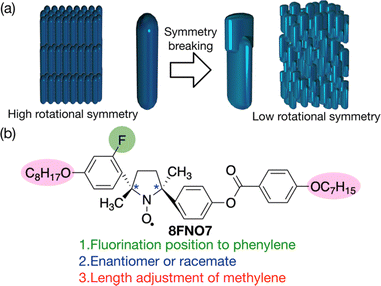
Since the rigid core generally decides the crystallinity of the LC materials, the modification of terminal units is not crucial for lowering the melting points; LC-NRs show melting points higher than 60 °C regardless of terminal units.33–37 To lower the melting temperature (Tf = ΔHf/ΔSf), we should design the compound with a lower enthalpy of fusion (ΔHf) or a larger entropy of fusion (ΔSf). Since the number of phenylene groups cannot be lower than three for LC-NRs not to lose the liquid crystallinity,28 the chiral resolution is the only way to decrease ΔHf. This effect is expected to be too small to lower Tf to ambient temperature.28 We should focus on the increase of the difference in configurational entropy between crystal and LC phases. The configurational entropy can be reduced in crystals even by one substitution that breaks molecular symmetry, whereas the configurational entropy in LC phases is independent of the same substitution because the molecules can rotate there.38 Therefore, we anticipated that symmetry breaking by substituting any hydrogen atom in the phenylenes decreases the melting point, as shown in Fig. 1a. The fluorination seems appropriate due to the stability of C–F bonds and the smallest size in all possible substituents; its minimal bulkiness would hardly hinder the rod-like shape leading to the liquid crystallinity, whereas its size larger than hydrogen atom could sterically destabilize one of the conformations of the rigid groups.
Here, we describe the actual synthesis of an LC-NR showing an N* phase with a low melting point (<40 °C) by lateral fluorination (8FNO7), as shown in Fig. 1b. The molecular design process leading to this molecular structure will be unraveled in turn; three points should be noticed for energetically destabilizing crystal phases to lower melting points: fluorination, chirality and alkyl chain length. Then, we test the durability and tractability of the prepared LC-NR by detecting its magnetic structures induced by the deposited iron film using photoemission electron microscopy (PEEM) in a high vacuum under synchrotron radiation.
Results and discussion
Fluorination for decreasing entropy in crystal
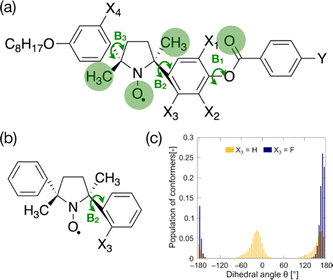
To lower the configurational entropy of crystals, the rotational symmetry of the three bonds between rigid groups (B1–B3 in Fig. 2a) should be broken by fluorine substituents and carbonyl or methyl groups. To inhibit the rotation around these bonds, we must consider only four fluorination positions (X1–X4 positions in Fig. 2a). We synthesized fluorinated analogs, as shown in Scheme S1 (ESI†). The lateral fluorination at the ortho-position of the phenoxy oxygen in a phenyl benzoate moiety typically often disrupts molecular packing in the Cr phases of calamitic LC compounds and keeps melting points low.39,40 We synthesized compounds laterally fluorinated at X1 and X2 positions. The fluorination at these positions leads to undesired results; melting points are hardly influenced by the fluorine substituents, as shown in Table S1 (ESI†). Moreover, the fluorination at these positions (X1 and X2) is likely to destabilize LC phases; the clearing points decrease about 15 °C with the fluorination at each position, and the N phases of some compounds consequently become monotropic. These results indicate that each rigid moiety in LC-NRs has a different role in deciding the phase behaviors. The phenyl benzoate group must rotate around the B1 bond to stabilize LC phases better than isotropic phases. The bulky five-membered-ring NR moiety in the mesogen core, in which 2,5-dimethyl-2,5-diphenylpyrrolidin-1-oxy (DDPO moiety) is chemically stabilized by the bulkiness, would dominate the molecular packing that decides the stability of crystalline phases.The fluorination at the X3 and X4 positions should inhibit the rotation of the bonds in the DDPO group. First, we examine the effect of the fluorination at the X3 position. It tends to slightly but surely lower melting points and to maintain the stability of LC phases; the melting points of (±)-8NOF8 and (±)-8NOFC8 are 5.2 and 20.1 °C lower than the corresponding non-fluorinated compounds (±)-8NO8 and (±)-8NOC8, respectively, as shown in Table S2 (ESI†).
To confirm the influences of fluorination at this position, the dihedral angle (N1–C6–C7–C8) and bond angle (N1–C2–C5) were calculated as a function of the dihedral angle θ (N1–C2–C3–C4) for the fluorinated (X3 = F) and non-fluorinated (X3 = H) DDPO shown in Fig. 2b at the UBLYP/6-31G** level using the Gaussian 09 program package, as shown in Fig. S1 (ESI†).41 The results of conformational analyses by DFT calculations suggest that the fluorination drastically changes the conformational ensemble, as shown in Fig. 2c. The conformation of fluorinated DDPO (X3 = F) is biased to θ = ±180° so that the fluorine atom avoids getting closer to the NR oxygen. The increase of ΔSf lowers Tf. The conformational bias is likely to give rise to the chemical stability, too. Moreover, the fluorination at the X4 position is expected to be as effective as that at the X3 position. The fluorination at the X4 position does not seem effective for the racemates, as listed in Table S3 (ESI†). These results differ completely from those in enantiomerically enriched LC-NRs fluorinated at the X3 and X4 positions.
Chiral resolution for decreasing the symmetry
In the case of LC-NRs, racemates tend to constitute more stable crystal structures than the enantiomers of the same compounds.24,35,37 It suggests that we are hopefully able to thermally destabilize the crystal structure very much. The decrease of ΔHf lowers Tf. However, whether racemates or pure enantiomers thermally stabilize the crystal structure depends on the intermolecular arrangement of the molecules packed in the crystal. We have no choice but to try to synthesize the analogs.We carried out the chiral resolution of racemates by high-performance liquid chromatography (HPLC) using a chiral column, as shown in Fig. S2 (ESI†). Enantiomerically enriched fluorinated compounds (2S,5S)-8NOF8 and (2R,5R)-8FNO8 show much lower melting points than their racemates (±)-8NOF8 and (±)-8FNO8, whereas non-fluorinated (±)-8NO8 and (2S,5S)-8NO8 show similar melting points to each other, as shown in Table S2 (ESI†).
Alkyl chain length for worse packing
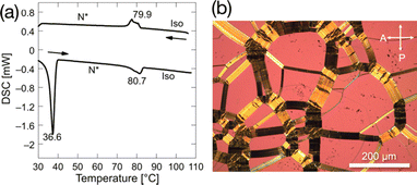
To lower melting points as much as possible, we fine-tuned the length of alkoxy side chains of the enantiomerically enriched LC-NR fluorinated at the most effective position, as shown in Table S4 (ESI†). All compounds show enantiotropic N* phases and lower melting points than the corresponding racemates. Among them, (2S,5S)-8FNO7 has the lowest melting point of 36.6 °C and the widest N* phase temperature range of 43.6 °C, as shown in Fig. 3. The enantiomerically enriched 8FNO7 (> 99% ee) showed a lower melting point than the samples with lower ee, as shown in Fig. S3 (ESI†). These results confirm that paired enantiomers would promote the molecular packing to form high melting-point racemic compound (RC) crystals. It is supported by an X-ray crystal structure of (2S,5S)-8FNO7, as shown in Table S5 and Fig. S4 (ESI†).In addition, (2S,5S)-8FNO7 has high thermal stability up to 200 °C in the air, as shown in Fig. S5 (ESI†) and moisture tolerance. Its chemical stability, low melting point, and wide temperature range of the N* phase should be advantageous to PEEM. These results imply that the design of the LC molecule with a functional moiety should be started from the modification around the functional moiety. In addition to breaking rotational symmetry around the DDPO moiety in (2S,5S)-8FNO7, breaking mirror symmetry destabilizes the high melting-point RC crystalline phase.
Magnetic properties of (2S,5S)-8FNO7
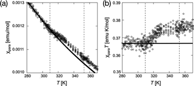
As another requirement for PEEM combined with the X-ray magnetic circular dichroism (XMCD), we confirmed the magnetic properties of (2S,5S)-8FNO7 using superconducting quantum interference device (SQUID) magnetometry and electron paramagnetic resonance (EPR) spectroscopy, as shown in Fig. 4 and Fig. S6–S12 (ESI†). Crystals of (2S,5S)-8FNO7 showed weak antiferromagnetic interactions in the low-temperature range, whereas N* and isotropic (Iso) phases of (2S,5S)-8FNO7 exhibited a positive magneto-LC effect; the paramagnetic susceptibility χpara distinctively increases by SQUID magnetometry with 0.05 T of the magnetic field, as shown in Fig. 4, and the relative magnetic susceptibility χrel increases by 14.7% by EPR spectroscopy with 0.33 T of the magnetic field at the Cr–to–N* phase transition (36.6 °C) in the first heating process like the non-fluorinated compound (2S,5S)-8NO8, as shown in Fig. S11 (ESI†). The increase in magnetic susceptibility is well-known to depend on the magnetic field.20,21,24,26,28 These results indicate that almost all radicals are alive and they can interact with the other paramagnetic substances. The fluorination at the X4 position near NR oxygen did not disrupt magnetic properties in the fluid phases.Photoemission electron microscopy (PEEM)
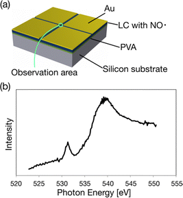
We can test the durability of (2S,5S)-8FNO7 using PEEM because the sample must be put in a high vacuum under synchrotron radiation. We measured X-ray absorption spectroscopy (XAS) using the PEEM. First, (2S,5S)-8FNO7 was spin-coated on a P-type silicon substrate. Note that poly(vinyl alcohol) (PVA) was spin-coated onto the Si substrate before applying the LC-NR because of the poor wettability of the substrate. To overcome the charging problem that may occur for insulating (2S,5S)-8FNO7 in electron imaging, we employed the method of Au pattern deposition, as schematically shown in Fig. 5a.42 The sample was covered by thick Au (∼100 nm) except for a thin area for the observation with a 30 mm width. The XAS spectra were obtained by extracting X-ray PEEM image intensities with sweeping photon energies across the O K-absorption edges, as shown in Fig. 5b. It suggests that the edges originate from the LC-NR containing oxygen atoms. The LC-NR is stable in a vacuum and stable against synchrotron radiation.X-ray magnetic circular dichroism (XMCD)
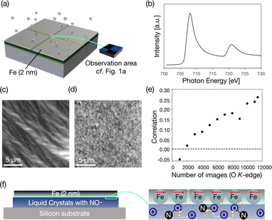
Furthermore, XMCD-PEEM is the most powerful method for detecting magnetic structures. Although XMCD-PEEM is generally used to measure the domains of ferromagnetic materials, it can also be used to measure the magnetic structures of paramagnetic materials like oxygen atoms. Magnetic moments can be induced into oxygen atoms or carbon monoxide molecules contacting ferromagnetic metal through exchange interactions.43,44 We confirmed that the oxygen atoms are likely to be magnetized by the direct exchange interactions with the iron film, as shown in Fig. S13 (ESI†).We deposited iron (2 nm) on (2S,5S)-8FNO7 covered by thick Au except for a thin observation area of the width of 30 μm (Fig. 6a). XAS spectra of the sample at the Fe L3-edge were drawn using the same method mentioned above (Fig. 6b). It means that the thin film is not iron oxide but iron metal. Then, we took XMCD-PEEM images to visualize the magnetic domains of the thin iron film, as shown in Fig. 6c. The XMCD-PEEM image of the Fe L3-edge exhibits a clear domain structure. We confirmed that the XMCD image contrast varies by changing the direction of incident X-ray beams (by rotating the sample in-plane), as shown in Fig. S14 (ESI†), suggesting that the iron film has in-plane magnetization. We took the XMCD-PEEM images at the O K-edge in the same field of view (30![[thin space (1/6-em)]](https://www.rsc.org/images/entities/char_2009.gif) 976 pixels) for Fe L3-edge measurement. The XMCD-PEEM image of the O K-edge exhibits a very faint but discernible XMCD contrast indicative of the induced magnetic domain structure of (2S,5S)-8FNO7, as shown in Fig. 6d. We verified that the correlation between the XMCD contrast of the Fe L3-edge and the O K-edge almost linearly increases as we add up the number of obtained XMCD-PEEM images of the O K-edge from 10
976 pixels) for Fe L3-edge measurement. The XMCD-PEEM image of the O K-edge exhibits a very faint but discernible XMCD contrast indicative of the induced magnetic domain structure of (2S,5S)-8FNO7, as shown in Fig. 6d. We verified that the correlation between the XMCD contrast of the Fe L3-edge and the O K-edge almost linearly increases as we add up the number of obtained XMCD-PEEM images of the O K-edge from 10![[thin space (1/6-em)]](https://www.rsc.org/images/entities/char_2009.gif) 000 to 114
000 to 114![[thin space (1/6-em)]](https://www.rsc.org/images/entities/char_2009.gif) 000, as shown in Fig. 6e. (2S,5S)-8FNO7 was stable after the synchrotron radiation in a vacuum for one week. Although the XMCD-PEEM signal might depend on the morphology of samples, the correlation is sufficient (0.26). We can conclude that the XMCD contrast at the O K-edge derives from the magnetization induced by iron atoms.
000, as shown in Fig. 6e. (2S,5S)-8FNO7 was stable after the synchrotron radiation in a vacuum for one week. Although the XMCD-PEEM signal might depend on the morphology of samples, the correlation is sufficient (0.26). We can conclude that the XMCD contrast at the O K-edge derives from the magnetization induced by iron atoms.
Experimental
General information
Mass spectra were recorded on a JEOL JMS-700. IR spectra were recorded with a SHIMADZU IRAffinity-1 using the KBr-pellet technique. Elemental analyses (CHN) were carried out using a PerkinElmer 2400II. The g-values and hyperfine coupling constants (aN) were determined by the EPR spectra of tetrahydrofuran (THF) solutions at room temperature recorded with a JEOL JES-FE1XG in a magnetic field of about 0.33 T (X-band). Magnetization was recorded with a QUANTUM DESIGN MPMS-3. Phase behaviors were determined by differential scanning calorimetry (SHIMADZU DSC-60) and polarized optical microscopy (Olympus BX51). A hot stage (Japan High Tech 10083) was used as the temperature control unit for the microscopy. The thermal stability of compounds was evaluated by thermogravimetric analysis (SHIMADZU DTG-60). Bright-field optical microscope equipped with a CMOS camera (Point Grey, FL3-U3-13S2C-CS) was used to observe the generation processes of microcapsules. Unless otherwise noted, solvents and reagents were reagent grade and used without further purification. THF that was used for chemical reactions and the EPR spectroscopy was distilled from sodium/benzophenone ketyl under nitrogen. Silicon substrates for XAS and XMCD-PEEM were p-type silicon (NILACO, Japan, resistivity ≦ 0.02 Ω cm−1).Phase transition
The phase behaviors were characterized by differential scanning calorimetry (DSC) at a scanning rate of 2 °C min−1 upon first heating and cooling processes and by polarized optical microscopy (POM).Conformational analysis
We conducted conformational analyses to study shape symmetry and molecular dipole moments by DFT calculations at the UB3LYP/6-31G** level using Gaussian 09 program package.41 The energy of each conformer of the derivatives as a substructure of the LC-NRs was calculated as a function of dihedral angle θ. And we also calculated the population of each conformer by assuming Boltzmann distribution at 300 K as follows. | (1) |
Evaluation of magnetic properties by SQUID magnetometry
In the first heating process, the temperature dependences of molar magnetic susceptibility χM were measured on an MPMS superconducting quantum interference device (SQUID) magnetometer. Each 5–10 mg sample was enclosed in a DSC aluminum pan to prevent the sign inversion of the total magnetic susceptibility of samples mounted in a drinking straw in high-temperature ranges. Curie constant C and Weiss constant θ were evaluated by fitting experimental magnetic susceptibility data with the following equation involving the term of Curie–Weiss law and small diamagnetic contribution χdia, | (2) |
Sample preparation for XAS and XMCD-PEEM
An aqueous solution (0.1 wt%) of poly(vinyl alcohol) (PVA, Mw = 1500, 86–89% hydrolyzed) was spin-coated at 200 rpm on the Si and ITO substrates. After drying the substrates at 180 °C for 12 h, a hexane solution (0.1 wt%) of (2S,5S)-8FNO7 was spin-coated at 5000 rpm on PVA. To effectively release the positive charges created by photoemission, we deposited ex situ thick (typically ∼100 nm) Au films just around the observation area (30 mm). Then, we deposited in situ thin (typically ∼2 nm) Fe films.XAS and XMCD-PEEM
The experiments were performed at the PEEM experimental station of beamline BL17SU (a-branch) of SPring-8.45,46 In this beamline, circularly or linearly polarized soft X-rays (200–2000 eV) generated from a multi-polarization-mode undulator are available.47 Although the soft X-ray beams can be focused down to ∼15 μm by a condensing mirror, we used unfocused beam (∼1 mm) for this experiment to minimize irradiation damage inflicted on the organic LC-NR sample. We employed a spectroscopic photoemission/low-energy-electron microscope (SPELEEM; Elmitec Co. Ltd), achieving a spatial resolution of ∼23 nm even in PEEM experiments in the soft X-ray region.48 All experiments were performed under a pressure of approximately 3–5 × 10⁻⁹ torr and at room temperature.Correlation between the XMCD-PEEM image at the Fe L3-edge and that at the O K-edge
We estimated the correlation between the XMCD-PEEM image with 176 × 176 (30976) pixels at the Fe L3-edge and that at the O K-edge by comparing the difference from the average brightness value for each pixel. Correlation (r) is calculated as | (3) |
![[x with combining macron]](https://www.rsc.org/images/entities/i_char_0078_0304.gif) and ȳ are the average of the brightness values for the images at the Fe L3-edge and the O K-edge, respectively, and n is the number of pixels.
and ȳ are the average of the brightness values for the images at the Fe L3-edge and the O K-edge, respectively, and n is the number of pixels.
Conclusions
A comprehensive design strategy based on the conformational distribution lowers melting points while keeping magnetic properties. The obtained compound shows the lowest melting point (36.6 °C), the widest enantiotropic N* phase temperature range (43.6 °C), high thermal and chemical stability, and a positive magneto-LC effect. The design strategy focusing on conformational ensembles in the most influential substructure in the crystallinity would be universally applicable to organic materials. The PEEM of the new LC-NR suggests its durability in a vacuum and in synchrotron radiation. We observed XMCD-PEEM of the new material. This is the first work to visualize the magnetic structures in LC phases. Furthermore, this compound would be widely applicable as a metal-free compound for magnetically transportable carriers in optofluidics.49–52Author contributions
Y. U., T. A. and T. O. designed the study; T. A., D. K., X.-Q. M., S. N. and T. Y. performed the synthesis, the measurements and the analyses of phase behavior and magnetic properties; T. O. performed the XAS and XMCD-PEEM measurement and their analyses; Y. U., T. A., T. O. and N. N. wrote the paper. All authors discussed and commented on the paper.Data availability
The data supporting this article have been included as part of the ESI.†Conflicts of interest
There are no conflicts to declare.Acknowledgements
The experiments at SPring-8 were performed with the approval of the Japan Synchrotron Radiation Research Institute (Proposal No. 2016B1189, 2017A1220, 2017B1236, 2018A1183, 2018A1404, 2018B1096 and 2018B1075 (BL17SU)). The authors extend appreciation to Professor Tsuyoshi Kimura, the University of Tokyo, for SQUID magnetometry, to Professor Takeshi Naota and Dr Takatoshi Maeda, Osaka University, for X-ray crystal structural analysis, to Professor Miki Hasegawa, Aoyama Gakuin University, and Professor Rui Tamura and Dr Naoto Nakano, Kyoto University, for helpful advice, and to Dr Misaki Ota, Mr Takeru Omiya, Mr Takuto Nakai, Mr Takuya Naruta, Mr Koki Sasaki, Ms Eriko Moriwaki, Osaka University, for XMCD-PEEM experiments. This work was supported in part by the Japan Science and Technology Agency (JST) ‘Precursory Research for Embryonic Science and Technology (PRESTO)’ for a project of ‘Molecular technology and creation of new function,’ by JSPS KAKENHI Grant Numbers JP17H04896, JP20K21226, JP20H05161 and JP22H02158, by “the Itoh Chubei Foundation,” and by “Toyota Physical and Chemical Research Institute Scholars.” T. A. is very grateful to the JSPS Research Fellowships for Young Scientists JP16J05585. The computations were performed using Research Center for Computational Science, Okazaki, Japan.Notes and references
- A. Nobel, US Pat., US78317A, 1868.
- P. Ravi, D. M. Badgujar, G. M. Gore, S. P. Tewari and A. K. Sikder, Propellants, Explos., Pyrotech., 2011, 36, 393–403 CrossRef CAS.
- J. J. Reilly Jr and R. H. Wiswall Jr, Inorg. Chem., 1968, 7, 2254–2256 CrossRef.
- C. Abetz, P. Georgopanos, C. Pistidda, T. Klassen and V. Abetz, Adv. Mater. Technol., 2022, 7, 2101584 CrossRef CAS.
- G. W. Gray, K. J. Harrison and J. A. Nash, Electron. Lett., 1973, 9, 130 CrossRef CAS.
- D. Dunmur and T. Sluckin, Soap, Science, and Flat-Screen TVs: A History of Liquid Crystals, Oxford Univ Pr on Demand, Oxford, 2014 Search PubMed.
- M. S. Whittingham, Science, 1976, 192, 1126–1127 CrossRef CAS.
- A. Magasinski, P. Dixon, B. Hertzberg, A. Kvit, J. Ayala and G. Yushin, Nat. Mater., 2010, 9, 353–358 CrossRef CAS PubMed.
- M. Li, J. Lu, Z. Chen and K. Amine, Adv. Mater., 2018, 30, 1800561 CrossRef PubMed.
- J. Lopez, D. G. Mackanic, Y. Cui and Z. Bao, Nat. Rev. Mater., 2019, 4, 312–330 CrossRef CAS.
- J. Piątek, S. Afyon, T. M. Budnyak, S. Budnyk, M. H. Sipponen and A. Slabon, Adv. Energy Mater., 2021, 11, 2003456 CrossRef.
- H. Shirakawa, E. J. Louis, A. G. MacDiarmid, C. K. Chiang and A. J. Heeger, J. Chem. Soc., Chem. Commun., 1977, 578–580 RSC.
- S. C. Rasmussen, ChemPlusChem, 2020, 85, 1412–1429 CrossRef CAS PubMed.
- P. T. Nyffeler, S. G. Durón, M. D. Burkart, S. P. Vincent and C.-H. Wong, Angew. Chem., Int. Ed., 2005, 44, 192–212 CrossRef CAS.
- B. Gutmann, D. Cantillo and C. O. Kappe, Angew. Chem., Int. Ed., 2015, 54, 6688–6728 CrossRef CAS PubMed.
- O. O. Grygorenko, D. M. Volochnyuk and B. V. Vashchenko, Eur. J. Org. Chem., 2021, 6478–6510 CrossRef CAS.
- T. Saito, Y. Nishiyama, J.-L. Putaux, M. Vignon and A. Isogai, Biomacromolecules, 2006, 7, 1687–1691 CrossRef CAS.
- M. W. Dale and C. J. Wedge, Chem. Commun., 2016, 52, 13221–13224 RSC.
- B. Liu, C. W. Tang, H. Jiang, G. Jia and T. Zhao, ACS Sustainable Chem. Eng., 2021, 9, 6258–6265 CrossRef CAS.
- Y. Uchida, N. Ikuma, R. Tamura, S. Shimono, Y. Noda, J. Yamauchi, Y. Aoki and H. Nohira, J. Mater. Chem., 2008, 18, 2950–2952 RSC.
- Y. Uchida, K. Suzuki, R. Tamura, N. Ikuma, S. Shimono, Y. Noda and J. Yamauchi, J. Am. Chem. Soc., 2010, 132, 9746–9752 CrossRef CAS.
- P. Ravat, T. Marszalek, W. Pisula, K. Müllen and M. Baumgarten, J. Am. Chem. Soc., 2014, 136, 12860–12863 CrossRef CAS PubMed.
- S. Kapuściński, J. Szczytko, D. Pociecha, M. Jasiński and P. Kaszyński, Mater. Chem. Front., 2021, 5, 6512–6521 RSC.
- K. Suzuki, Y. Uchida, R. Tamura, S. Shimono and J. Yamauchi, J. Mater. Chem., 2012, 22, 6799–6806 RSC.
- Y. Uchida, T. Sakaguchi, S. Oki, S. Shimono, J. Park, M. Sugiyama, S. Sato, E. Zaytseva, D. G. Mazhukin and R. Tamura, ChemPlusChem, 2022, 87, e202100352 CrossRef CAS PubMed.
- S. Nakagami, T. Akita, D. Kiyohara, Y. Uchida, R. Tamura and N. Nishiyama, J. Phys. Chem. B, 2018, 122, 7409–7415 CrossRef CAS PubMed.
- Y. Uchida, G. Watanabe, T. Akita and N. Nishiyama, J. Phys. Chem. B, 2020, 124, 6175–6180 CrossRef CAS PubMed.
- N. Ikuma, R. Tamura, S. Shimono, N. Kawame, O. Tamada, N. Sakai, J. Yamauchi and Y. Yamamoto, Angew. Chem., Int. Ed., 2004, 43, 3677–3682 CrossRef CAS.
- R. Tamura, Y. Uchida and K. Nagura, in Nitroxides, ed. O. Ouari and D. Gigmes, Royal Society of Chemistry, Cambridge, 2021, pp. 420–448 Search PubMed.
- H. Kawamoto, in 2012 Third IEEE HISTory of ELectro-technology CONference (HISTELCON), 2012, pp. 1–6.
- T. Ikeda and O. Tsutsumi, Science, 1995, 268, 1873–1875 CrossRef CAS.
- T. Ikeda, J. Mater. Chem., 2003, 13, 2037–2057 RSC.
- T. Akita, T. Yamazaki, Y. Uchida and N. Nishiyama, Polyhedron, 2017, 136, 79–86 CrossRef CAS.
- T. Akita, Y. Uchida and N. Nishiyama, Chem. Lett., 2016, 45, 910–912 CrossRef CAS.
- T. Akita, Y. Uchida, D. Kiyohara, S. Nakagami and N. Nishiyama, Ferroelectrics, 2016, 495, 97–104 CrossRef CAS.
- T. Akita, Y. Uchida and N. Nishiyama, Mol. Cryst. Liq. Cryst., 2015, 613, 174–180 CrossRef CAS.
- T. Akita, D. Kiyohara, T. Yamazaki, Y. Uchida and N. Nishiyama, J. Mater. Chem. C, 2017, 5, 12457–12465 RSC.
- R. Pinal, Org. Biomol. Chem., 2004, 2, 2692–2699 RSC.
- J. W. Goodby, E. J. Davis, R. J. Mandle and S. J. Cowling, Handbook of Liquid Crystals, John Wiley & Sons, Ltd, 2014, pp. 1–30 Search PubMed.
- M. J. S. Dewar and A. C. Griffin, J. Am. Chem. Soc., 1975, 97, 6662–6666 CrossRef CAS.
- M. J. Frisch, G. W. Trucks, H. B. Schlegel, G. E. Scuseria, M. A. Robb, J. R. Cheeseman, G. Scalmani, V. Barone, B. Mennucci, G. A. Petersson, H. Nakatsuji, M. Caricato, X. Li, H. P. Hratchian, A. F. Izmaylov, J. Bloino, G. Zheng, J. L. Sonnenberg, M. Hada, M. Ehara, K. Toyota, R. Fukuda, J. Hasegawa, M. Ishida, T. Nakajima, Y. Honda, O. Kitao, H. Nakai, T. Vreven, J. A. Montgomery, J. E. Peralta, F. Ogliaro, M. Bearpark, J. J. Heyd, E. Brothers, K. N. Kudin, V. N. Staroverov, R. Kobayashi, J. Normand, K. Raghavachari, P. G. Rendell, J. C. Burant, S. S. Iyengar, J. Tomasi, M. Cossi, N. Rega, J. M. Millam, M. Klene, J. E. Knox, J. B. Cross, V. Bakken, C. Adamo, J. Jaramillo, R. Gomperts, R. E. Stratmann, O. Yazyev, A. J. Austin, R. Cammi, C. Pomelli, J. W. Ochterski, R. L. Martin, K. Morokuma, V. G. Zakrzewski, G. A. Voth, P. Salvador, J. J. Dannenberg, S. Dapprich, A. D. Daniels, O. Farkas, J. B. Foresman, J. V. Ortiz, J. Cioslowski and D. J. Fox, Gaussian 09 Revision D.01, Gaussian, Inc., Wallingford CT, 2009 Search PubMed.
- T. Ohkochi, M. Kotsugi, K. Yamada, K. Kawano, K. Horiba, F. Kitajima, M. Oura, S. Shiraki, T. Hitosugi, M. Oshima, T. Ono, T. Kinoshita, T. Muro and Y. Watanabe, J. Synchrotron. Rad., 2013, 20, 620–625 CrossRef CAS PubMed.
- C. Sorg, N. Ponpandian, M. Bernien, K. Baberschke, H. Wende and R. Q. Wu, Phys. Rev. B: Condens. Matter Mater. Phys., 2006, 73, 064409 CrossRef.
- K. Amemiya, T. Yokoyama, Y. Yonamoto, M. Miyachi, Y. Kitajima and T. Ohta, Jpn. J. Appl. Phys., 2000, 39, L63 CrossRef CAS.
- H. Ohashi, Y. Senba, H. Kishimoto, T. Miura, E. Ishiguro, T. Takeuchi, M. Oura, K. Shirasawa, T. Tanaka, M. Takeuchi, K. Takeshita, S. Goto, S. Takahashi, H. Aoyagi, M. Sano, Y. Furukawa, T. Ohata, T. Matsushita, Y. Ishizawa, S. Taniguchi, Y. Asano, Y. Harada, T. Tokushima, K. Horiba, H. Kitamura, T. Ishikawa and S. Shin, AIP Conf. Proc., 2007, 879, 523–526 CrossRef CAS.
- Y. Senba, H. Ohashi, H. Kishimoto, T. Miura, S. Goto, S. Shin, T. Shintake and T. Ishikawa, AIP Conf. Proc., 2007, 879, 718–721 CrossRef CAS.
- K. Shirasawa, T. Tanaka, T. Seike, A. Hiraya and H. Kitamura, AIP Conf. Proc., 2004, 705, 203–206 CrossRef.
- F. Z. Guo, T. Muro, T. Matsushita, T. Wakita, H. Ohashi, Y. Senba, T. Kinoshita, K. Kobayashi, Y. Saitoh, T. Koshikawa, T. Yasue, M. Oura, T. Takeuchi and S. Shin, Rev. Sci. Instrum., 2007, 78, 066107 CrossRef CAS PubMed.
- J. S. Sander, R. M. Erb, C. Denier and A. R. Studart, Adv. Mater., 2012, 24, 2582–2587 CrossRef CAS PubMed.
- Y. Uchida, Y. Iwai, T. Akita, T. Mitome, K. Suzuki, R. Tamura and N. Nishiyama, J. Mater. Chem. B, 2014, 2, 4130–4133 RSC.
- L.-J. Chen, L.-L. Gong, Y.-L. Lin, X.-Y. Jin, H.-Y. Li, S.-S. Li, K.-J. Che, Z.-P. Cai and C. J. Yang, Lab Chip, 2016, 16, 1206–1213 RSC.
- A. S. Utada, E. Lorenceau, D. R. Link, P. D. Kaplan, H. A. Stone and D. A. Weitz, Science, 2005, 308, 537–541 CrossRef CAS.
Footnote |
| † Electronic supplementary information (ESI) available: Synthesis methods, synthetic scheme, characterization methods, phase transition behavior, calculation results, HPLC charts, X-ray crystallographic analysis, SQUID magnetometry, EPR spectroscopy, XMCD-PEEM; Scheme S1, Fig. S1–S14 and Tables S1–S4. CCDC 2251603 ((2S,5S)-8FNO7). For ESI and crystallographic data in CIF or other electronic format see DOI: https://doi.org/10.1039/d4tc04081c |
| This journal is © The Royal Society of Chemistry 2025 |

