Carbon intercalated porous NaTi2(PO4)3 spheres as high-rate and ultralong-life anodes for rechargeable sodium-ion batteries†
Hongbo
Geng‡
ab,
Jun
Yang‡
c,
Hong
Yu
a,
Chengchao
Li
*a and
Xiaochen
Dong
 *c
*c
aSchool of Chemical Engineering and Light Industry, Guangdong University of Technology, Guangzhou 510006, China. E-mail: licc@gdut.edu.cn
bKey Laboratory of Organic Synthesis of Jiangsu Province, College of Chemistry, Chemical Engineering and Materials Science and Collaborative Innovation Center of Suzhou Nano Science and Technology, Soochow University, Suzhou, 215123, China
cKey Laboratory of Flexible Electronics (KLOFE) & Institute of Advanced Materials (IAM), Jiangsu National Synergetic Innovation Center for Advanced Materials (SICAM), Nanjing Tech University (NanjingTech), 30 South Puzhu Road, Nanjing 211816, China. E-mail: iamxcdong@njtech.edu.cn
First published on 6th March 2017
Abstract
In this manuscript, a carbon intercalated porous NaTi2(PO4)3 (NTP@C) spherical composite was synthesized through a facile hydrolysis reaction combined with a subsequent hydrothermal and annealing process. Benefiting from the unique mesoporous architecture combined with the conductive carbon layer, the NTP@C composite showed excellent electrochemical properties in terms of both stable cycling performance and good rate capabilities. Evaluated as anodes for sodium-ion batteries, the NTP@C composites presented a high reversible specific capacity (around 134 mA h g−1 at a current rate of 1C) and an excellent cycling performance (about 81 mA h g−1 at a high current rate of 50C during the 1000th cycle). The remarkable electrochemical performance can be attributed to the rational design of the hybrid structure, which can ensure fast electron and sodium ion transport in the electrode materials.
Introduction
Sodium-ion batteries (SIBs) have attracted a great attention in recent years due to their easy availability and low cost compared to lithium-ion batteries (LIBs).1–5 However, the ionic radius and molar mass of Na+ is larger than that of Li+. Thus, SIBs suffer greatly from the larger volume change, lower specific capacity and shorter life cycles than those of LIBs.6–10 To overcome these problems, developing suitable electrode materials with low cost and excellent electrochemical properties is urgent for the practical application of SIBs. In the past few years, carbon-based materials,11,12 metal oxides,13 sulphides,14 sodium alloys,15 and titanium based compounds16 have been extensively investigated as anode materials for SIBs. Although tremendous efforts have been made to explore high-performance anode materials for SIBs, developing novel nanostructured electrode materials with high specific capacities, excellent rate capability, and long cycle life still appears to be challenging.Recently, sodium super-ionic conductor structured NaTi2(PO4)3 (NTP) has received great attention in the SIB field due to its stabilized three-dimensional framework, high theoretical capacity (133 mA h g−1), and good thermal stability.17–19 However, NTP suffers from low electrical conductivity during the Na-ion intercalation/de-intercalation process, leading to poor rate capability and rapid capacity fading.20,21 Therefore, novel structural designs and synthetic techniques are the most crucial points to address these problems. This can be accomplished by optimizing the NTP materials to nanostructures and encapsulating NTP with conducting materials in an attempt to increase the transport kinetics for both electrons and sodium ions.22,23
Recently, numerous efforts have been devoted to developing porous micro-/nanostructured materials with high surface area and a large nanoscale interior because these porous structures not only provide short diffusion pathways for sodium ions by enlarging the electrode–electrolyte contact area, but also supply extra voids to effectively withstand volume variation derived from the repeated sodium ions intercalation/de-intercalation process.24–27 For example, Gu et al.28 reported a scalable synthesis of Co3O4 porous cubes using Prussian blue (PB) microcubes as the sacrificial templates, which led to high specific capacity and stable cycling ability. Building carbon-based hybrid nanostructured architectures is also expected to improve the electrical/ionic transport kinetics of the electrode material.29–32 For example, Zheng et al.33 have synthesized carbon coated TiO2 spheres using ethylene diamine as a precursor by a facile solution-phase process incorporating a nanoscopic carbon coating, which formed a conducting network upon calcination. Based on the abovementioned design rationales, a rationally designed hybrid architecture, which consists of porous NTP spheres and uniformly distributed carbon, is believed to be a promising anode for SIBs.
Herein, we describe a facile three-step route to prepare carbon intercalated porous NaTi2(PO4)3 spheres (NTP@C) composed of self-assembled NaTi2(PO4)3 nanoparticles (about 5 nm in diameter) and uniformly distributed carbon. First, the titanium glycolate precursor spheres were synthesized via a hydrolysis process, and then NTP-precursors were hydrothermally synthesized. The final product of NTP@C could be obtained by the subsequent thermal process. It was found that the content of carbon was around 5% with a uniform distribution, which could greatly enhance the conductivity of the composite. Furthermore, the obtained porous NTP@C spheres had a high Brunauer–Emmett–Teller (BET) surface area (25.5 m2 g−1) and porous structure. Specifically, the spheres delivered a high reversible specific capacity (around 134 mA h g−1 at a current rate of 1C) and excellent cycling performance (about 81 mA h g−1 at a high current rate of 50C during the 1000th cycle), which was much higher than that of the pure NTP. Its exceptional performance makes it a promising candidate for sodium storage applications.
Results and discussion
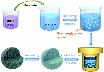
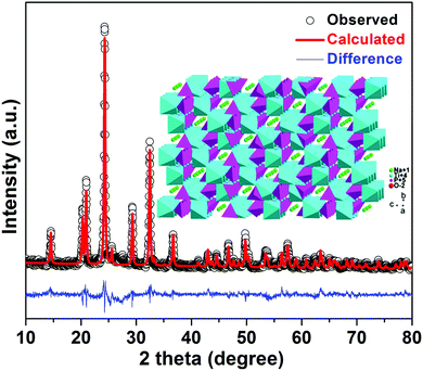
The fabrication process of porous NTP@C spheres is schematically illustrated in Fig. 1. First, the titanium glycolate precursor spheres could be obtained via a slow hydrolysis process of TBOT in EG and acetone mixture. As shown in Fig. S1 (ESI†), TEM images revealed that the as-prepared titanium glycolate precursors are uniform solid spheres with an average diameter of about 500 nm. Subsequently, the titanium glycolate precursor spheres were transformed into NTP-precursors in the presence of organic phosphoric acid and sodium acetate by a hydrothermal reaction. Finally, the porous NTP@C spheres were obtained after calcination. The residual carbon came from the organic phosphoric acid during the heat treatment, which was beneficial for the improvement of conductivity.Fig. 2 shows the X-ray diffraction (XRD) pattern of porous NTP@C spheres. The lattice parameters of NTP@C were calculated as a = 8.4830 Å, b = 8.4830 Å, and c = 21.8043 Å. Moreover, all refinements gave a small value of factors including Rwp and S, which indicated a good and reliable structural parameter (Table S1, ESI†). All of the diffraction peaks were in good agreement with the high purity NASICON-type framework (JCPDS no. 33-1296). The inset of Fig. 2 shows the framework structure of NTP, in which TiO6 octahedra and PO4 tetrahedra share all the corner oxygen atoms. This architecture with a 3D open framework structure was demonstrated to facilitate the transport of sodium ions.34 Raman spectroscopy was further carried out to confirm the existence of carbon in the composite. As shown in Fig. S2 (ESI†), two distinct peaks were observed at 1592 and 1349 cm−1, agreeing with the expected G and D bands of carbon, respectively. The D-band located at 1349 cm−1 was caused by the disorder-induced phonon mode, and the G-band at 1592 cm−1 was attributed to the E2g phonons of C sp2 atoms.35–37 Fig. S3 further shows the small-angle XRD patterns for the NTP-precursor and NTP@C composite. As shown in Fig. S3A (ESI†), the prominent peak was ascribed to the existence of layered titanium-based organic phosphate. After annealing, the peak disappeared (Fig. S3B, ESI†), indicating the transformation of organic phosphoric acid to carbon. Fig. S4 (ESI†) shows the TGA curve of the porous NTP@C spheres heating in air at a rate of 5 °C min−1. The weight loss below 100 °C could be assigned to the evaporation of the absorbed water. It could be seen that the carbon component was combusted into CO2 in the range of 600–700 °C, resulting in an abrupt weight loss of about 5 wt%.
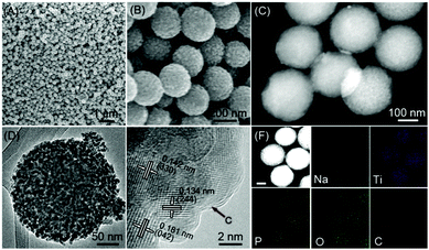
The morphologies of the as-synthesized porous NTP@C spheres were characterized by SEM and TEM images (Fig. 3A–F). It is clearly observed in Fig. 3A and B that the spherical morphological features of the samples are well maintained after the hydrothermal and carbonization process. In good agreement with the SEM results, the high-angle annular dark-field scanning transmission electron microscopy (HAADF-STEM) image (Fig. 3C) further demonstrates that the NTP@C spheres are composed of nanocrystals with an average diameter of around 220 nm. Fig. 3D indicates the mesoporous structure of the NTP@C spheres that can be clearly observed by the magnified TEM image. The high-resolution transmission electron microscopy (HRTEM) further reveals the good crystalline nature of NTP@C (Fig. 3E). The well-resolved lattice fringes with interplanar distances of 0.134, 0.142 and 0.181 nm can be indexed to (244), (330) and (042) planes of NTP, respectively. In addition, a carbon layer can be clearly seen in Fig. 3E (indicated by the black arrow). The HAADF-STEM image and the corresponding EDX elemental mapping images of NTP@C (Fig. 3F) further indicate the existence of Na, Ti, P, O and C elements, and all these elements are uniformly distributed throughout the single sphere. Nitrogen adsorption–desorption isotherms (Fig. S5, ESI†) were obtained to investigate the specific surface area and pore-size distribution of the NTP@C spheres. The BET specific surface area of the NTP@C sphere was determined to be 25.5 m2 g−1, and the BJH pore-size analysis (Fig. S5, ESI† inset) indicated the presence of mesopores with a well-defined pore size of about 2–10 nm.
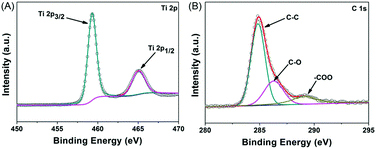
The chemical compositions and surface electronic states of the porous NTP@C spheres were further examined via X-ray photoelectron spectroscopy (XPS), as shown in Fig. 4A and B. The XPS high resolution spectrum of Ti 2p (Fig. 4A) could be deconvoluted into two pairs of doublets, 459.8 and 465.8 eV, by Gaussian curve fitting, which were assigned to Ti 2p3/2 and Ti 2p1/2 spin–orbital splitting photoelectrons, respectively.38,39 In the high-resolution C 1s XPS spectrum (Fig. 4B), the dominating peak centered at 284.7 eV was attributed to the C–C bonds, while the peaks located at 286.2 and 289.1 eV were ascribed to the C–O and O![[double bond, length as m-dash]](https://www.rsc.org/images/entities/char_e001.gif) C–O oxygen-containing functional groups, respectively.40,41
C–O oxygen-containing functional groups, respectively.40,41
To explore the effect of carbon on wettability, a dynamic contact angle measurement was performed on porous NTP@C spheres and the pure NTP with water, as illustrated in Fig. S6 (ESI†). The contact angle of porous NTP@C spheres with water was 65.4°, indicating its hydrophilic properties. However, the pure NTP showed an initial contact angle of 134.0°, which was almost two times larger than that of the porous NTP@C spheres. This result indicated that the wettability of porous NTP@C spheres could be enhanced by the effective functionalized carbon coating and lead to an improvement in the sodium storage properties.
Motivated by the interesting hybrid architectures composed of porous NTP spheres and uniform distributed carbon layer with high conductivity, the electrochemical performance of the porous NTP@C spheres was measured using the coin cells with sodium foil as both the counter and reference electrodes. Fig. 5A shows the typical discharge/charge profiles of the NTP@C electrodes at different current rates ranging from 1 to 50C, within the potential window of 1.2–2.8 V (vs. Na/Na+) (1C ≈ 133 mA g−1). It exhibited typical charge/discharge plateaus at 2.1 V, which could be assigned to the reaction of NaTi2(PO4)3 + 2Na+ + 2e− ↔ Na3Ti2(PO4)3.42 With the increase in current rates, the NTP@C voltage decreased but the shape of the curves was maintained, suggesting a good electrochemical stability of the porous NTP@C spheres as anodes for SIBs. The high-rate capability of the NTP@C electrode was also evaluated at different current rates ranging from 1 to 50C, as shown in Fig. 5B. Compared with pure NTP, the NTP@C electrode demonstrated high specific capacities of 134, 126, 119, 115, 113, 105, 96 and 83 mA h g−1 at the current rates of 1, 2, 5, 10, 20, 30, 40 and 50C, respectively. Importantly, the specific capacity of the NTP@C electrode at 1C could return to the initial value after the high-current rate measurements, which demonstrated the high reversibility of the NTP@C electrode. The excellent rate capability of NTP@C electrode could be attributed to the mesoporous structure with large surface area and good conductivity, which was beneficial to enhance the electrolyte/electrode contact area and improve the charge transfer during the Na-ion intercalation/de-intercalation process.
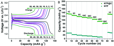 | ||
| Fig. 5 (A) Discharge and charge profiles of the porous NTP@C spheres and (B) rate performance of the NTP and NTP@C electrodes at different current rates. | ||
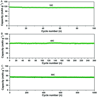
In addition, the NTP@C composite exhibited an excellent cycling performance (Fig. 6A–C). As shown in Fig. 6A, the NTP@C composite delivered a reversible capacity of around 110 mA h g−1 after 100 cycles at a current rate of 10C. It is well known that fast discharge/charge rate and long cycling performance are vital for practical applications. As shown in Fig. 6B and C, even after continuous cycling for 260 and 1000 cycles at current rates of 40 and 50C, the porous NTP@C spheres could still maintain high specific capacities of 92 and 81 mA h g−1, respectively. To understand the excellent Na storage performances, electrochemical impedance spectroscopy (EIS) was investigated to explore the electrochemical reaction kinetics of the NTP@C porous spheres. The Nyquist plots (Fig. S7, ESI†) consisted of a depressed semicircle in the high-medium frequency region and an inclined line in the low frequency region, respectively. The diameter of the semicircle corresponding to the charge transfer resistance was much smaller for the NTP@C electrode than that of the NTP, which was mainly attributed to the interconnection of NTP nanocrystals with the carbon network. In addition, the NTP@C electrode exhibited a higher slope for the line at low frequency, indicating a faster sodium ion diffusion process of the NTP@C electrode than that of the pure NTP.
Fig. 7 compares the electrochemical properties of our porous NTP@C spheres with those carbon-based NTP composites reported in literature. It was evident that the porous NTP@C spheres obtained in the present study exhibited comparable or even higher rate capability than various other NTP anode materials, such as carbon nanotube/NaTi2(PO4)3,43 NaTi2(PO4)3@rGO,44 NaTi2(PO4)3–graphene composite,45 NaTi2(PO4)3@porous carbon,46 porous NaTi2(PO4)3–C array,47 NaTi2(PO4)3@C nanocomposite,48 NaTi2(PO4)3/C porous plates49 and mesoporous NaTi2(PO4)3/CMK-3,50 suggesting that our porous NTP@C spheres are promising candidates to build superior electrochemical energy-storage devices with good rate capability. The superior sodium storage performance of the porous NTP@C spheres might be due to the synergistic coupling effects of the porous NTP spheres/carbon composite: (1) the void space in the porous structure can serve as a reservoir for electrolyte immersion, which provides an effective diffusion distance for sodium ions, and (2) the presence of carbon guarantees excellent electrical networks and acts as a conductive link to ensure fast electron transfer between the nearby NTP nanoparticles.
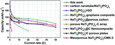 | ||
| Fig. 7 Comparison of the sodium storage properties of the porous NTP@C spheres to those carbon-based NTP composite materials reported in other studies. | ||
Conclusions
In summary, we developed a facile synthetic strategy to prepare uniform porous NTP@C spheres as anodes for high-rate and ultralong-life sodium-ion batteries. Owing to the rational combination of the merits of a porous structure and carbon network, high electrical conductivity and efficient sodium ion transport was achieved. When evaluated as an anode material for sodium ion batteries, the porous NTP@C spheres demonstrated a high reversible sodium storage capacity of 134 mA h g−1 at the current rate of 1C, and excellent cycling performance (e.g. 81 mA h g−1 at a current rate of 50C during the 1000th cycle), which makes it attractive as a promising anode of high performance sodium-ion batteries.Experimental
Synthesis of titanium glycolate precursor spheres
The titanium glycolate precursor spheres were synthesized according to literature with some modification. In a typical experiment, tetrabutoxytitanium (TBOT, Aldrich) was added into ethylene glycol (EG, 50 mL; Merck) under vigorous stirring. Then, the mixture was bubbled with nitrogen for about 30 min to remove water and oxygen. After that, the mixture was poured into 200 mL of acetone, followed by addition of 2.7 mL water under strong stirring. One hour later, white precipitate was collected by centrifugation and washed with ethanol several times.Synthesis of carbon intercalated porous NaTi2(PO4)3 spheres (denoted as NTP@C)
The as-prepared titanium glycolate precursor was dispersed into 40 mL of deionized (DI) water containing 3 mmoles of sodium acetate. Afterwards, organic phosphoric acid (decylphosphoric acid), in a stoichiometric amount, was added into the abovementioned mixture under vigorous stirring. The mixture was transferred into a Teflon-lined autoclave (50 mL) and kept in an electric oven at 180 °C for 12 h. After cooling down to room temperature, the white NTP-precursor was collected by centrifugation and washed with DI water and ethanol several times, and dried in an oven at 80 °C for 12 h. Finally, the product was calcined at 750 °C for 4 h in forming gas (5% H2).Characterization
The morphology of the samples was investigated using a field-emission scanning electron microscope (FESEM, JEOL, Model JSM-7600F). Transmission electron microscope (TEM) images were taken on a JEOL 2100F operating at 200 kV. The crystal structure observation of the samples was carried out using a Shimadzu 6000 X-ray diffractometer at a scan rate of 2° min−1 using Cu Kα1 (λ = 0.15406 nm) radiation. An accelerated surface area and porosimetry system (ASAP 3020) was used for the measurement of nitrogen adsorption/desorption isotherms. X-ray photoelectron spectroscopy (XPS) was performed by an AXIS-His (Kratos Analytical). Thermogravimetric analysis (TGA) of the samples was conducted on a Mettler Toledo TGA/DSC1 Simultaneous Thermal Analyzer in air (10 °C min−1).Electrochemical testing
The working electrode was prepared by mixing the active materials (NTP or NTP@C) and carbon black (Super P) with a binder of polyvinylidene fluoride (PVDF) at a weight ratio of 70![[thin space (1/6-em)]](https://www.rsc.org/images/entities/char_2009.gif) :
:![[thin space (1/6-em)]](https://www.rsc.org/images/entities/char_2009.gif) 20
20![[thin space (1/6-em)]](https://www.rsc.org/images/entities/char_2009.gif) :
:![[thin space (1/6-em)]](https://www.rsc.org/images/entities/char_2009.gif) 10 in N-methylpyrrolidone (NMP) solvent. The mixed slurry was coated onto a copper foil current collector and dried overnight in a vacuum oven at 60 °C. Finally, the electrode sheets were pressed under a force of approximately 10 MPa and cut into circular sheets. The loading of the active material on the electrode was about 1.5 mg cm−2. The electrochemical measurements were carried out using two-electrode coin cells (X2 Labwares, Singapore) with sodium foil as both the counter and reference electrodes at room temperature. Glass fibers (Whatman GF/D) were used as the separator, and the electrolyte was 1 M NaClO4 in the mixture of ethylene carbonate and propylene carbonate (1
10 in N-methylpyrrolidone (NMP) solvent. The mixed slurry was coated onto a copper foil current collector and dried overnight in a vacuum oven at 60 °C. Finally, the electrode sheets were pressed under a force of approximately 10 MPa and cut into circular sheets. The loading of the active material on the electrode was about 1.5 mg cm−2. The electrochemical measurements were carried out using two-electrode coin cells (X2 Labwares, Singapore) with sodium foil as both the counter and reference electrodes at room temperature. Glass fibers (Whatman GF/D) were used as the separator, and the electrolyte was 1 M NaClO4 in the mixture of ethylene carbonate and propylene carbonate (1![[thin space (1/6-em)]](https://www.rsc.org/images/entities/char_2009.gif) :
:![[thin space (1/6-em)]](https://www.rsc.org/images/entities/char_2009.gif) 1, volume). All the cells were tested by a NEWARE multi-channel battery test system at various currents in the voltage range of 1.2–2.8 V. Electrochemical impedance spectroscopy for electrode before cycling was conducted at a frequency ranging from 100 kHz to 10 MHz with an alternating current amplitude of 5 mV.
1, volume). All the cells were tested by a NEWARE multi-channel battery test system at various currents in the voltage range of 1.2–2.8 V. Electrochemical impedance spectroscopy for electrode before cycling was conducted at a frequency ranging from 100 kHz to 10 MHz with an alternating current amplitude of 5 mV.
Acknowledgements
We acknowledge the financial support from the Program for One Hundred Person Project of Guangdong University of Technology, the NNSF of China (61525402, 5161101159), and the QingLan Project.Notes and references
- N. Yabuuchi, K. Kubota, M. Dahbi and S. Komaba, Chem. Rev., 2014, 114, 11636–11682 CrossRef CAS PubMed
.
- H. G. Kim, J. H. Hong, K. Y. Park, H. S. Kim, S. W. Kim and K. S. Kang, Chem. Rev., 2014, 114, 11788–11827 CrossRef CAS PubMed
.
- Y. Z. Jiang, M. J. Hu, D. Zhang, T. Z. Yuan, W. P. Sun, B. Xu and M. Yan, Nano Energy, 2014, 5, 60–66 CrossRef CAS
.
- S. W. Kim, D. H. Seo, X. Ma, G. Ceder and K. Kang, Adv. Energy Mater., 2012, 2, 710–721 CrossRef CAS
.
- Y. You, X. Q. Yu, Y. X. Yin, K. W. Nam and Y. G. Guo, Nano Res., 2015, 8, 117–128 CrossRef CAS
.
- S. P. Ong, V. L. Chevrier, G. Hautier, A. Jain, C. Moore, S. Kim, X. Ma and G. Ceder, Energy Environ. Sci., 2011, 4, 3680–3688 CAS
.
- Y. Wen, K. He, Y. Zhu, F. Han, Y. Xu, I. Matsuda, Y. Ishii, J. Cumings and C. Wang, Nat. Commun., 2014, 5, 4033–4042 CAS
.
- D. Kundu, E. Talaie, V. Duffort and L. F. Nazar, Angew. Chem., Int. Ed., 2015, 54, 3431–3448 CrossRef CAS PubMed
.
- Y. Xu, M. Zhou, X. Wang, C. Wang, L. Liang, F. Grote, M. Wu, Y. Mi and Y. Lei, Angew. Chem., Int. Ed., 2015, 54, 8768–8771 CrossRef CAS PubMed
.
- J. Sun, H. W. Lee, M. Pasta, H. Yuan, G. Zheng, Y. Sun, Y. Li and Y. Cui, Nat. Nanotechnol., 2015, 10, 980–985 CrossRef CAS PubMed
; S. Yuan, Y. H. Zhu, W. Li, S. Wang, D. Xu, L. Li, Y. Zhang and X. B. Zhang, Adv. Mater., 2017, 29, 1602469 CrossRef PubMed
.
- S. Wenzel, T. Hara, J. Janek and P. Adelhelm, Energy Environ. Sci., 2011, 4, 3342–3345 CAS
.
- S. Wang, L. Xia, L. Yu, L. Zhang, H. Wang and X. W. Lou, Adv. Energy Mater., 2016, 6, 1502217 CrossRef
.
- H. Xiong, M. D. Slater, M. Balasubramanian, C. S. Johnson and T. Rajh, J. Phys. Chem. Lett., 2011, 2, 2560–2565 CrossRef CAS
; S. Yuan, X. L. Huang, D. L. Ma, H. G. Wang, F. Z. Meng and X. B. Zhang, Adv. Mater., 2014, 26, 2273–2279 CrossRef PubMed
.
- Z. Hu, Z. Zhu, F. Cheng, K. Zhang, J. Wang, C. Chen and J. Chen, Energy Environ. Sci., 2015, 8, 1309–1316 Search PubMed
; S. Wang, S. Yuan, Y. B. Yin, Y. H. Zhu, X. B. Zhang and J. M. Yan, Part. Part. Syst. Charact., 2016, 33, 493–499 CrossRef CAS
; S. Yuan, S. Wang, L. Li, Y. H. Zhu, X. B. Zhang and J. M. Yan, ACS Appl. Mater. Interfaces, 2016, 8, 9178–9184 Search PubMed
.
- J. Liu, Y. Wen, P. A. van Aken, J. Maier and Y. Yu, Nano Lett., 2014, 14, 6387–6392 CrossRef CAS PubMed
.
- C. Chen, Y. Wen, X. Hu, X. Ji, M. Yan, L. Mai, P. Hu, B. Shan and Y. Huang, Nat. Commun., 2015, 6, 6929–6936 CrossRef CAS PubMed
; H. G. Wang, S. Yuan, D. L. Ma, X. B. Zhang and J. M. Yan, Energy Environ. Sci., 2015, 8, 1660–1681 Search PubMed
.
- C. Wu, P. Kopold, Y.-L. Ding, P. A. van Aken, J. Maier and Y. Yu, ACS Nano, 2015, 9, 6610–6618 CrossRef CAS PubMed
.
- Z. Li, D. Young, K. Xiang, W. C. Carter and Y.-M. Chiang, Adv. Energy Mater., 2013, 3, 290–294 CrossRef CAS
.
- X. Wu, Y. Cao, X. Ai, J. Qian and H. Yang, Electrochem. Commun., 2013, 31, 145–148 CrossRef CAS
.
- W. Wu, J. Yan, A. Wise, A. Rutt and J. F. Whitacre, J. Electrochem. Soc., 2014, 161, A561–A567 CrossRef CAS
.
- J. Yang, H. Wang, P. Hu, J. Qi, L. Guo and L. Wang, Small, 2015, 11, 3744–3749 CrossRef CAS PubMed
.
- B. Zhao, Q. Wang, S. Zhang and C. Deng, J. Mater. Chem. A, 2015, 3, 12089–12096 CAS
.
- G. Yang, H. Song, M. Wu and C. Wang, J. Mater. Chem. A, 2015, 3, 18718–18726 CAS
.
- L. B. Ma, R. P. Chen, Y. Hu, G. Y. Zhu, T. Chen, H. L. Lu, J. Liang, Z. X. Tie, Z. Jin and J. Liu, Nanoscale, 2016, 8, 17911–17918 RSC
; J. Y. Wang, H. J. Tang, H. Wang, R. B. Yu and D. Wang, Mater. Chem. Front., 2017, 1, 414–430 RSC
; H. Li, H. R. Ma, M. Yang, B. Wang, H. Shao, L. Wang, R. B. Yu and D. Wang, Mater. Res. Bull., 2017, 87, 224–229 CrossRef CAS
; F. Wang, J. Y. Wang, H. Ren, H. J. Tang, R. B. Yu and D. Wang, Inorg. Chem. Front., 2016, 3, 365–369 RSC
.
- H. Z. Li, L. Y. Yang, J. Liu, S. T. Li, L. B. Fang, Y. K. Lu, H. R. Yang, S. L. Liu and M. Lei, J. Power Sources, 2016, 324, 780–787 CrossRef CAS
; J. Zhang, H. Ren, J. Y. Wang, J. Qi, R. B. Yu, D. Wang and Y. L. Liu, J. Mater. Chem. A, 2016, 4, 17673–17677 Search PubMed
; H. Ren, J. J. Sun, R. B. Yu, M. Yang, L. Gu, P. Liu, H. J. Zhao, D. Kisailus and D. Wang, Chem. Sci., 2016, 7, 793–798 RSC
; J. Y. Wang, H. J. Tang, L. J. Zhang, H. Ren, R. B. Yu, Q. Jin, J. Qi, D. Mao, M. Yang, Y. Wang, P. Liu, Y. Zhang, Y. R. Wen, L. Gu, G. H. Ma, Z. G. Su, Z. Y. Tang, H. J. Zhao and D. Wang, Nat. Energy, 2016, 1, 16050 CrossRef
.
- X. T. Zhang, J. S. Zhou, C. C. Liu, X. H. Chen and H. H. Song, J. Mater. Chem. A, 2016, 4, 8837–8843 Search PubMed
; H. Ren, R. B. Yu, J. Y. Wang, Q. Jin, M. Yang, D. Mao, D. Kisailus, H. J. Zhao and D. Wang, Nano Lett., 2014, 14, 6679–6684 CrossRef CAS PubMed
; S. M. Xu, C. M. Hessel, H. Ren, R. B. Yu, Q. Jin, M. Yang, H. J. Zhao and D. Wang, Energy Environ. Sci., 2014, 7, 632–637 Search PubMed
.
- J. S. Cho, S. Y. Lee and Y. C. Kang, Sci. Rep., 2016, 6, 23338 CrossRef CAS PubMed
; J. Y. Wang, N. L. Yang, H. J. Tang, Z. H. Dong, Q. Jin, M. Yang, D. Kisailus, H. J. Zhao, Z. Y. Tang and D. Wang, Angew. Chem., Int. Ed., 2013, 52, 6417–6420 CrossRef PubMed
.
- H. B. Geng, Y. Y. Guo, X. G. Ding, H. W. Wang, Y. F. Zhang, X. L. Wu, J. Jiang, J. W. Zheng, Y. G. Yang and H. W. Gu, Nanoscale, 2016, 8, 7688–7694 RSC
.
- T. Ramireddy, N. Sharma, T. Xing, Y. Chen, J. Leforestier and A. M. Glushenkov, ACS Appl. Mater. Interfaces, 2016, 8, 30152–30164 CAS
.
- Y. Wang, D. Z. Kong, W. H. Shi, B. Liu, G. J. Sim, Q. Ge and H. Y. Yang, Adv. Energy Mater., 2016, 6, 1601057 CrossRef
.
- Y. Zhang, C. W. Foster, C. E. Banks, L. D. Shao, H. S. Hou, G. Q. Zou, J. Chen, Z. D. Huang and X. B. Ji, Adv. Mater., 2016, 28, 9391–9399 CrossRef CAS PubMed
.
- H. Liu, M. Q. Jia, Q. Z. Zhu, B. Cao, R. J. Chen, Y. Wang, F. Wu and B. Xu, ACS Appl. Mater. Interfaces, 2016, 8, 26878–26885 CAS
.
- Y. Fu, H. Ming, Q. Zhou, L. L. Jin, X. W. Li and J. W. Zheng, Electrochim. Acta, 2014, 134, 478–485 CrossRef CAS
.
- C. Delmas, F. Cherkaoui, A. Nadiri and P. Hagenmuller, Mater. Res. Bull., 1987, 22, 631–639 CrossRef CAS
.
- Y. Shi, J. Z. Wang, S. L. Chou, D. Wexler, H. J. Li, K. Ozawa, H. K. Liu and Y. P. Wu, Nano Lett., 2013, 13, 4715–4720 CrossRef CAS PubMed
.
- X. L. Wu, L. Y. Jiang, F. F. Cao, Y. G. Guo and L. J. Wan, Adv. Mater., 2009, 21, 2710–2714 CrossRef CAS
.
- Y. Z. Li, Z. Zhou, X. P. Gao and J. Yan, J. Power Sources, 2006, 160, 633–637 CrossRef CAS
.
- J.-H. Yun, R. J. Wong, Y. H. Ng, A. Du and R. Amal, RSC Adv., 2012, 2, 8164–8171 RSC
.
- L. Jing, H. L. Tan, R. Amal, Y. H. Ng and K.-N. Sun, J. Mater. Chem. A, 2015, 3, 15675–15682 CAS
.
- O. Akhavan and E. Ghaderi, Nanoscale, 2013, 5, 10316–10326 RSC
.
- Y. Fang, L. Xiao, J. Qian, Y. Cao, X. Ai, Y. Huang and H. Yang, Adv. Energy Mater., 2016, 6, 1502197 CrossRef
.
- Y. Jiang, J. Shi, M. Wang, L. Zeng, L. Gu and Y. Yu, ACS Appl. Mater. Interfaces, 2016, 8, 689–695 CAS
.
- G. B. Xu, L. W. Yang, X. L. Wei, J. W. Ding, J. X. Zhong and P. K. Chu, J. Power Sources, 2016, 327, 580–590 CrossRef CAS
.
- J. J. Song, S. Park, J. Gim, V. Mathew, S. Kim, J. Jo, S. Kim and J. Kim, J. Mater. Chem. A, 2016, 4, 7815–7822 CAS
.
- G. Pang, C. Z. Yuan, P. Nie, B. Ding, J. J. Zhu and X. G. Zhang, Nanoscale, 2014, 6, 6328–6334 RSC
.
- Y. Jiang, L. C. Zeng, J. Q. Wang, W. H. Li, F. S. Pan and Y. Yu, Nanoscale, 2015, 7, 14723–14729 RSC
.
- B. D. Zhao, B. Lin, S. Zhang and C. Deng, Nanoscale, 2015, 7, 18552–18560 RSC
.
- D. X. Wang, Q. Liu, C. J. Chen, M. L. Li, X. Meng, X. F. Bie, Y. J. Wei, Y. H. Huang, F. Du, C. Z. Wang and G. Chen, ACS Appl. Mater. Interfaces, 2016, 8, 2238–2246 CAS
.
- Z. F. Huang, L. Liu, L. G. Yi, W. Xiao, M. Li, Q. Zhou, G. X. Guo, X. Y. Chen, H. B. Shu, X. K. Yang and X. Y. Wang, J. Power Sources, 2016, 325, 474–481 CrossRef CAS
.
- G. Pang, P. Nie, C. Z. Yuan, L. F. Shen, X. G. Zhang, H. S. Li and C. L. Zhang, J. Mater. Chem. A, 2014, 2, 20659–20666 CAS
.
Footnotes |
| † Electronic supplementary information (ESI) available. See DOI: 10.1039/c7qm00048k |
| ‡ These authors contribute equally. |
| This journal is © the Partner Organisations 2017 |

