 Open Access Article
Creative Commons Attribution 3.0 Unported Licence
In situ growth of binder-free CoNi0.5-MOF/CC electrode for high-performance flexible solid-state supercapacitor application†
Weijie
Zhang‡
ab,
Zhen
Cao‡
b,
Yuying
Li
b,
Ruiting
Li
b,
Yanmei
Zheng
c,
Ping
Su
a and
Xinli
Guo
 *b
*b
aChongqing Key Laboratory of New Energy Storage Materials and Devices, School of Science, Chongqing University of Technology, Chongqing 40054, China
bSchool of Materials Science and Engineer, Southeast University, Nanjing 211189, China. E-mail: guo.xinli@seu.edu.cn
cJiangsu Co-Innovation Center of Efficient Processing and Utilization of Forest Resources, International Innovation Center for Forest Chemicals and Materials, College of Chemical Engineering, Nanjing Forestry University, Longpan Road 159, Nanjing 210037, China
First published on 9th April 2024
Abstract
Metal organic frameworks (MOFs) with binder-free electrodes have shown promise for portable electrochemical energy storage applications. However, their low specific capacitance and challenges associated with the attachment of active materials to the substrate constrain their practical utility. In this research, we prepared a CoNi0.5-MOF/CC electrode by in situ growth of CoNi0.5-MOF on an H2O2-pretreated carbon cloth (CC) without using any binder. It exhibits a higher specific capacitance of 1337.5 F g−1 than that of CoNi0.5-MOF (∼578 F g−1) at a current density of 1 A g−1 and an excellent rate ability of 88% specific capacitance retention at a current density of 10 A g−1 after 6000 cycles. The as-assembled flexible asymmetric solid-state supercapacitor based on the CoNi0.5-MOF/CC positive electrode and a nitrogen-doped graphene (N-Gr) negative electrode exhibits an energy density of 61.46 W h kg−1 at a power density of 1244.56 W kg−1 and holds a stable capacitance of ∼125 F g−1 at 1 A g−1 when the flexible supercapacitor is bent, showing great potential for flexible electronics application. The H2O2 is indicated to play an important role, enhancing the adhesion of CoNi0.5-MOF on CC and reducing its charge transfer resistance by functionalizing the carbon fiber during the pretreatment of the CC matrix. The results provide a great way to prepare a flexible asymmetric solid-state supercapacitor with both high power density and high energy density for practical application.
Introduction
Portable and wearable energy storage devices are attracting more interest with the demand for smartphones, electronic skin, and other intelligent devices. Flexible energy storage devices with high-performance electrochemical characteristics and good mechanical properties are becoming more and more important.1–3 Flexible all-solid-state supercapacitors provide fast charging and discharging processes, excellent power density and high cycle stability, which are ideal for powering portable devices. As part of a flexible device, the importance of a flexible electrode with superior mechanical properties, high conductivity, and low resistance of the electrode active materials in a flexible supercapacitor cannot be overstated.In the realm of supercapacitors, electrode materials hold paramount significance, with ongoing efforts directed towards the development of novel materials such as graphene, MXene, metal-organic frameworks (MOFs), and others, aimed at enhancing device performance. MOF materials, which are among the novel materials, consist of metal clusters and ligands. Previous research has shown that supercapacitors can take advantage of this material directly as an electrode material.4–6 Among them, the contact between the electrode and electrolyte can be facilitated by a porous structure in the material, thereby creating a double electric layer effect, and metal ions can undergo certain redox reactions with the electrolyte, resulting in pseudo-capacitance.7,8 In the previous works, Ni-MOF,9,10 Co-MOF,11,12 Fe-MOF,13 and Ni/Co-MOF,14,15 among others, showed great potential as supercapacitor electrode materials. Among them, the bimetal Ni/Co-MOF has a higher capacitance and more promising performance than the single MOF due to its high electrochemical activity. We also prepared Co/Ni-MOF powder material and studied the molar ratio of Co and Ni for their effects on electrochemical performance.16 The prepared CoNi0.5-MOF shows a relatively high capacitance of 578 F g−1. However, there is still scope for improving its capacity properties. To improve the performance, using a binder-free electrode is effective, since the electrochemical properties of powder electrode materials are hindered by the binder material, which decreases the electron storage capacity and the transfer of ions. Thus, it is preferable to directly grow the active material without a binder on the collector substrate to avoid the binder as well as improve the electrochemical performance.17–19
CC (carbon cloth) is considered as an appropriate substrate for flexible electrodes due to its flexibility and electrical conductivity. Furthermore, because of its wearability, intrinsic flexibility in mechanics, light weight and ease of integration with other materials, CC-based flexible devices have great potential for commercial use in practical applications. However, bare CC, when used as a MOF-based electrode matrix, exhibits unsatisfying performance in terms of inferior conductivity and electrochemical activity. To address the issues of bare CC, some strategies for improving CC performance have been presented, such as wet chemical oxidation, electrochemical oxidation, plasma modification etc.
Xu and co-workers prepared directly grown CoNi-MOF on CC with the hierarchical layered structure of ultrathin nanosheets and nanotube arrays, showing a high area capacity of 1.01 C cm−2 at 2 mA cm−2.20 To improve the hydrophilic and oxygen-containing functional groups on the CC, Ma and co-workers pretreated the CC with UV-ozone for 15 min, and then directly grew ZIF-67 on it. As a result, the maximum specific area capacitance of this hybrid electrode in 2 M KOH aqueous solution is 1756 mF cm−2.21 Liu prepared manganese-based MOF on the surface of CC using a facile hydrothermal method. During the electrode preparation process, the commercially available original CC was ultrasonically rinsed for 30 min using 3 M HCl, absolute ethanol, and deionized water to increase the oxygen functional groups on the surface of the CC.22 To develop a high-performance MOF electrode, Wallace and co-workers pretreated the commercial CC and activated it in H2SO4/HNO3 mixture at 70 °C for 3 hours, then by electrodeposition process, they successfully prepared the Co-MOF on pretreated CC, and the electrode showed superior capacitive performance.23 However, to date, most carbon fibers or CC need to be treated with nitric acid or other strong corrosive fluids before their use as an electrode substrate, resulting in high energy demand and environmental contamination. Furthermore, natural and synthetic fabrics are typically passive in terms of electronic transmission, and the binding force between the load material and the textile is rather modest, as the physical contact interface is typically facilitated by van der Waals forces. As a result, the active material may fall off or be lost during the electrochemical reaction or mechanical deformation. Furthermore, the area capacitance generated by the electrode faces difficulty meeting the criteria due to the limited amount of active material in the load. Therefore, it is preferable to develop highly hydrophilic CC or textile with plentiful oxygen functional groups, and to enhance the pretreatment process to maximize the active material loading and specific capacitance of flexible electrode materials.24,25
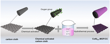
In this study, aimed at enhancing the performance of MOF material on a carbon cloth (CC) substrate, we present a straightforward pretreatment method for bare CC utilizing hydrogen peroxide, thereby avoiding the use of highly corrosive acids (Fig. 1). The resultant CoNi0.5-MOF, grown in situ on the pretreated CC (CoNi0.5-MOF/CC), exhibits outstanding capacitive properties, indicating promising potential for applications in flexible electronics.
Experimental
In situ growth of CoNi0.5-MOF on CC
The commercial CC was pretreated to modify the oxygen functional groups and surface hydrophilic properties. KOH, H2O2 and a mixture of HNO3, H2SO4 and KMnO4 were used to pretreat the CC, respectively. The chemical processes were as follows: (1) CC was immersed into 2 M KOH solution and kept at 80 °C for 6 hours; (2) a few pieces of CC were dropped into 30% H2O2 and kept at 50 °C for 6 hours; (3) some pieces of CC were modified with a mixture of concentrated HNO3, H2SO4 and KMnO4 (HNO3/H2SO4/KMnO4 mixture). When the reaction finished, the CC was cleaned with deionized water and ethanol several times and dried under vacuum in an oven.According to our previous report,16 the precursor solution of CoNi0.5-MOF was prepared. Subsequently, the pretreated carbon cloth was soaked in a Co(NO3)2 and Ni(NO3)2 solution, which included Co and Ni in a 1![[thin space (1/6-em)]](https://www.rsc.org/images/entities/char_2009.gif) :
:![[thin space (1/6-em)]](https://www.rsc.org/images/entities/char_2009.gif) 0.5 ratio, then 1,3,5-benzenetricarboxylic acid (H3BTC) was added dropwise to the above beaker. After stirring for 30 min, the mixture was moved to the autoclave and reacted at 160 °C for 6 hours. When the reaction finished and the temperature decreased to ambient temperature, the CoNi0.5-MOF/CC was obtained after several washes with deionized water and ethanol, and the electrode was placed in a vacuum oven to dry overnight.
0.5 ratio, then 1,3,5-benzenetricarboxylic acid (H3BTC) was added dropwise to the above beaker. After stirring for 30 min, the mixture was moved to the autoclave and reacted at 160 °C for 6 hours. When the reaction finished and the temperature decreased to ambient temperature, the CoNi0.5-MOF/CC was obtained after several washes with deionized water and ethanol, and the electrode was placed in a vacuum oven to dry overnight.
Characterization
In this work, the hydrophobicity of pretreated CC was tested by an optical contact angle measurement device (LAUDA Scientific, OSA100) using a droplet (3 μL) of water as an indicator at room temperature. Infrared spectrometry (FT-IR, Thermo Fisher Scientific, Nicolet 5700) was used to characterize the oxygen group induced by the different chemical modifications. X-ray diffractometry (XRD, Bruker, D8-Discover, λ = 1.5418 Å) with Cu Kα radiation was conducted to analyze the structure of the prepared material at the range of 10–80°. The morphology and chemical composition of the samples were characterized by scanning electron microscopy (SEM, Thermo Fisher Scientific, Sirion) and determined by energy dispersive spectroscopy (EDS), respectively.Electrochemical test
An electrochemical workstation (CHI 660D) with a three-electrode system was used to evaluate the electrochemical performance of the electrode materials. Typically, 2 M KOH was used as the electrolyte. The counter electrode and reference electrode were platinum wire and Hg/HgO, respectively. For cyclic voltammetry (CV), the voltage window ranged from 0 to 0.6 V and the scan rate ranged from 1 to 50 mV s−1. In order to test the capability of the prepared electrode materials, the galvanostatic charging/discharging (GCD) test was applied. The GCD test potential window was 0–0.6 V at current densities ranging from 1 to 30 A g−1. The cycle stability was tested using GCD method, with 6000 cycles and a test current density of 10 A g−1. For the electrochemical impedance spectra (EIS), the open-circuit voltage was set as the initial voltage, amplitude was 5 mV, and the frequency range was 0.01 Hz–100 kHz. In three-electrode test systems, the specific capacitance of the electrode material was measured by the following eqn (1): | (1) |
 | (2) |
 | (3) |
Results and discussion
The hydrophilicity of the substrate is very important, as it affects the in situ growth process of the active material. Hydrophilicity tests were performed to determine the optimal carbon fabric treatment for electrode material preparation. As shown in Fig. 2(a), the hydrophilicity test showed that the untreated carbon fiber has a higher contact angle and stronger hydrophobicity. The contact angles of the modified carbon fabrics with KOH decreased, but remained hydrophobic (Fig. 2b). In contrast, the HNO3/H2SO4/KMnO4 mixture-treated carbon cloth and the H2O2-treated carbon cloth are more hydrophilic (Fig. 2c and d), ensuring the active material grew uniformly on the carbon fabric during the hydrothermal process. Compared to treatment with HNO3/H2SO4/KMnO4 mixture, the same hydrophilic effect can be achieved with H2O2 pretreatment, which is not only more environmentally friendly but also a simpler process. Therefore, this experiment demonstrates that H2O2-pretreated CC can serve as an ideal in situ growth substrate for active electrode materials. The specific surface structure and functional groups were analyzed by the following FT-IR characterization.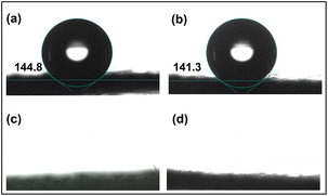 | ||
| Fig. 2 Hydrophilicity test of CC after different pretreatment processes: (a) original CC; (b) treated with KOH; (c) treated with HNO3/H2SO4/KMnO4 mixture; (d) treated with H2O2. | ||
The CCs were treated using different methods and examined by infrared spectroscopy to determine the functional groups on the surface. As depicted in Fig. 3(a), the infrared spectrum of the unhydroxylated original CC exhibits no discernible peaks corresponding to oxygen-related functional groups. In comparison, the H2O2 and HNO3/H2SO4/KMnO4 mixture added typical hydroxyl and other oxygen-containing functional groups to CC. The result indicates that H2O2 and the HNO3/H2SO4/KMnO4 mixture can significantly modify the surface structure of the carbon fabric. Specifically, the H2O2 and HNO3/H2SO4/KMnO4 mixture-modified CCs exhibit the absorption peak of –OH at about 3440 cm−1–3650 cm−1 and the stretching vibration peak of –C–H at about 1560 cm−1.20,27 In addition, for the CC pretreated with H2O2, the characteristic peak of –C![[double bond, length as m-dash]](https://www.rsc.org/images/entities/char_e001.gif) O appeared at approximately 2250 cm−1. The above oxygen groups are responsible for the hydrophilic properties. For comparison, we also used KOH as a modification agent and pretreated the CC for 6 h. As shown in Fig. 3(a), it is evident that despite the high alkalinity of KOH, the surface modification effect is insufficient. Compared to the strong oxidant HNO3/H2SO4/KMnO4-mixture-pretreated CC, the H2O2-pretreated CC not only has the same excellent hydrophilicity, but also newly introduced oxygen-containing groups. Considering the importance of environmental and operational safety and performance, we propose that using the alkali is difficult to oxidize or modify the CC, and compared to the highly corrosive and oxidizing HNO3/H2SO4/KMnO4 mixture, H2O2 can serve as an effective, safe and facile agent for modifying oxygen-containing functional groups on CC.
O appeared at approximately 2250 cm−1. The above oxygen groups are responsible for the hydrophilic properties. For comparison, we also used KOH as a modification agent and pretreated the CC for 6 h. As shown in Fig. 3(a), it is evident that despite the high alkalinity of KOH, the surface modification effect is insufficient. Compared to the strong oxidant HNO3/H2SO4/KMnO4-mixture-pretreated CC, the H2O2-pretreated CC not only has the same excellent hydrophilicity, but also newly introduced oxygen-containing groups. Considering the importance of environmental and operational safety and performance, we propose that using the alkali is difficult to oxidize or modify the CC, and compared to the highly corrosive and oxidizing HNO3/H2SO4/KMnO4 mixture, H2O2 can serve as an effective, safe and facile agent for modifying oxygen-containing functional groups on CC.
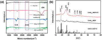 | ||
| Fig. 3 (a) FT-IR spectra of carbon cloth under different treatments; (b) XRD patterns of CoNi0.5-MOF and CoNi0.5-MOF/CC. | ||
XRD analysis was carried out to investigate the phase structures of the CoNi0.5-MOF powder and CoNi0.5-MOF/CC samples. The results of Fig. 3(b) indicate that the material synthesized on CC exhibits the same phase structure as the powdered material, consistent with the XRD pattern (CDCC-245714) reported in literature for Co-BTC material.28 Nevertheless, it is noteworthy that the peaks of CoNi0.5-MOF/CC at positions (0−21) and (−112) appear broader than those of the powder, implying a reduction in crystal size for the material grown on the substrate. Moreover, the presence of CC substrate gives rise to an evident (002) carbon material crystal face, as evidenced by the corresponding peak. Additionally, the CoNi0.5-MOF material tends to preferentially grow along the (031) crystal plane when deposited on the carbon fabric. These findings elucidate the influence of the substrate on the growth orientation of the material.
The morphologies of CC and CoNi0.5-MOF/CC material were characterized by SEM. Fig. 4(a and b) depicts the morphologies of carbon fabric at different magnifications. The pretreated pure CC exhibits a smooth surface and no impurities. After the hydrothermal process, MOF material successfully grows onto the surface of CC fiber, facilitated by the existence of oxygen-containing groups on the surface. Fig. 4(c and d) demonstrates that the active material is evenly coated around the carbon fabric, assuming a structure formed by the cross-linking of nanosheets and nanorods. Further observation of the higher-magnification TEM image (ESI Fig. S1†) reveals the nanomaterial nature of the materials with porous structure, consistent with the results of SEM.
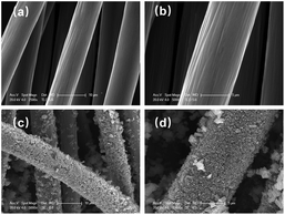 | ||
| Fig. 4 SEM images of (a and b) H2O2-pretreated CC substrate and (c and d) CoNi0.5-MOF/CC at different magnifications. | ||
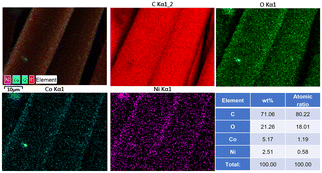
EDS was used to analyse the elements in the CoNi0.5-MOF/CC samples. As shown in Fig. 5, the material is primarily composed of C, O, Co and Ni, and all elements are distributed evenly on the surface of the CC fiber substrate. In addition, Ni and Co elements were distributed in the same area of the mapping, indicating that the Ni element is well combined with the ligand and successfully doped into Co-MOF. The table insert in Fig. 5 shows the semi-quantitative element content of the prepared material. It indicates that the ratio of Co to Ni atoms is close to 2![[thin space (1/6-em)]](https://www.rsc.org/images/entities/char_2009.gif) :
:![[thin space (1/6-em)]](https://www.rsc.org/images/entities/char_2009.gif) 1, which agrees with the predetermined experimental result. Combined with the XRD results, we successfully prepared CoNi0.5-MOF/CC electrode material via H2O2 modification of the surface chemical properties of CC.
1, which agrees with the predetermined experimental result. Combined with the XRD results, we successfully prepared CoNi0.5-MOF/CC electrode material via H2O2 modification of the surface chemical properties of CC.
The electrochemical performance of CoNi0.5-MOF/CC and CoNi0.5-MOF materials was tested using a three-electrode system. The CoNi0.5-MOF electrode was made from a mixture of the active material, conductive carbon and binder in the ratio of 8![[thin space (1/6-em)]](https://www.rsc.org/images/entities/char_2009.gif) :
:![[thin space (1/6-em)]](https://www.rsc.org/images/entities/char_2009.gif) 1
1![[thin space (1/6-em)]](https://www.rsc.org/images/entities/char_2009.gif) :
:![[thin space (1/6-em)]](https://www.rsc.org/images/entities/char_2009.gif) 1 by weight. After sufficient grinding and mixing with NMP solution, the paste was applied to nickel foam for testing. In contrast, CoNi0.5-MOF in situ grown on the CC can be tested immediately without the need for any conductive material or binder. In the three-electrode test, the platinum wire electrode and Hg/HgO were used as counter electrode and reference electrode, respectively.
1 by weight. After sufficient grinding and mixing with NMP solution, the paste was applied to nickel foam for testing. In contrast, CoNi0.5-MOF in situ grown on the CC can be tested immediately without the need for any conductive material or binder. In the three-electrode test, the platinum wire electrode and Hg/HgO were used as counter electrode and reference electrode, respectively.
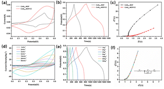
The CV curves of CoNi0.5-MOF and CoNi0.5-MOF/CC are shown in Fig. 6(a) at a scan rate of 10 mV s−1. It shows that all the electrodes have nearly clear redox peaks, indicating certain pseudo-capacitive characteristics. The CoNi0.5-MOF/CC electrode has a larger area at the same scan rate as the powder material, showing that the electrode has a higher specific capacity. According to our previous report,16 CoNix-MOFs with different Co and Ni atomic ratios were prepared, and among them, CoNi0.5-MOF has the most advanced capacitance storage. Charge and discharge properties of CoNi0.5-MOF/CC and CoNi0.5-MOF were measured by galvanostatic charge and discharge test. Fig. 6(b) shows that the different electrode materials all have specific charging/discharging platforms, and the voltage locations of the platforms are comparable and consistent with the CV results, indicating that redox reactions of reactive substances occur in the same way. During charging and discharging, the redox reactions of Ni2+ and Ni3+ as well as Co2+ and Co3+ ions are responsible for the high specific capacitance and the charge–discharge curve plateau. According to the GCD curve test results, the specific capacitance of CoNi0.5-MOF/CC at 1 A g−1 current density is 1337.5 F g−1, while the specific capacitance of CoNi0.5-MOF is 578 F g−1. The results reveal that in situ developed CoNi0.5-MOF material on CC has improved electrochemical performance.
The electrode reaction's kinetic process can be effectively reflected by EIS. Fig. 6(c) shows the EIS spectrum of the electrode material in the frequency range of 0.01 Hz–100 kHz under voltage disturbance with amplitude of 5 mV. The electrode resistance and charge transfer resistance are in the high-frequency region, and the Warburg impedance formed by electrolyte diffusion in the electrode is in the low-frequency area.29 Due to the addition of a conductive substance, the powder electrode has a smaller Rs (0.54 Ω) than the CoNi0.5-MOF/CC. However, CoNi0.5-MOF/CC has a decreased charge transfer resistance because electrolyte ions may easily diffuse to the reactive site of the electrode material without conductive agents and binders. Furthermore, the as-prepared CoNi0.5-MOF/CC electrode material has a lower Warburg impedance, indicating that the in situ grown material has sufficient contact with the electrolyte and superior electrochemical performance.
To further investigate the electrochemical performance of CoNi0.5-MOF/CC, Fig. 6(d) shows the CV curves of CoNi0.5-MOF/CC electrodes at various scan rates. The electrode displays a strong redox peak at a low scan rate. Ions can be absorbed to the surface and inside of the material at slow scan rates, resulting in a typical redox reaction. However, the redox peak weakens with increasing scan rate because surface adsorption is the predominant electrochemical process at high sweep speed, and there is some electrochemical polarization, thus the redox peak has a certain divergence.30,31 GCD tests were conducted to assess the rate performance of the CoNi0.5-MOF/CC electrode at different current densities. Fig. 6(e) shows that when current density increases, the electrode exhibits a fast charge/discharge ability and good reversibility. The discharge time of the electrode is 749 seconds when the current density is 1 A g−1. The fully charged electrode can be released in only 13 seconds when the current density is 30 A g−1, demonstrating remarkable high-power charge–discharge performance. Fig. 6(f) shows the EIS spectrum of CoNi0.5-MOF/CC and the inserted equivalent resistance fitted by Zview software. The result shows that the prepared electrodes have very low charge transfer resistance (0.38 Ω), allowing the electrolyte ion to effectively diffuse into the active site.
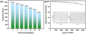
Electrode rate performance and cycle stability are important for practical application. Fig. 7(a) shows that the specific capacitance values of the CoNi0.5-MOF/CC electrode are 1337.5 F g−1, 1267.5 F g−1, 1205.3 F g−1, 1146.8 F g−1, 1040.8 F g−1, 961.5 F g−1, and 872.6 F g−1 at the current densities of 1 A g−1, 2 A g−1, 3 A g−1, 5 A g−1, 10 A g−1, 20 A g−1 and 30 A g−1, respectively. Even with a 30 A g−1 current density, the electrode can still reach 872.6 F g−1, indicating good rate performance. Furthermore, the electrode was tested for cycling performance over 6000 charge/discharge cycles at 10 A g−1, as shown in Fig. 7(b). The result shows that the material keeps 88% of its original capacity after cycling tests, showing remarkable cycle stability. Fig. S2 and S3† verified that the excellent rate performance and cycling stability of the material are attributable to the chemical binding of the active material with the CC substrate, and the material's stable nanostructure provides buffer space for expansion during the charging/discharging process.
We utilized the analysis method given by Dunn32 and Trassatti33 to investigate the charge storage dynamics of the CoNi0.5-MOF/CC electrode. The overall capacity stored in the electrode material can be categorized into the capacitance produced by diffusion and surface reaction processes using Dunn's kinetic method. In detail, the capacitance of the material at different scanning rates during CV testing is analyzed by following eqn (4):
| i = avb | (4) |
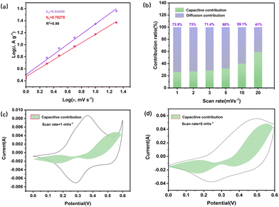
where i is the peak current (A) of the CV curve, v is the scan rate (V s−1), and the slope b can be calculated from the log(i) vs. log(v). Here, b = 0.5 represents the diffusion control process, while b = 1 represents the surface capacitance process. As shown in Fig. 8(a), the anode and cathode values are b = 0.84458 and b = 0.70279, respectively, showing that the surface process dominates capacitance. Fig. 8(b) shows the change in the capacitance's contribution to charge storage at different scanning rates. As shown in Fig. 8(b), the electrochemical reaction is dominated by ion diffusion and redox reaction at a low scan rate. The surface reaction becomes more dominant in the electrochemical reaction, and the capacitance contribution eventually increases.
The contribution of surface processing capacitance to the total charge is further investigated at different scan rates, and Dunn's method was applied to fit and analyse the CV curves. The results show that at low scan rates, the capacitance contribution is minimal. At low scan rates, the electrolyte ions have enough time to penetrate into the electrode material, resulting in less surface capacitive behaviour. With the scan rate increase, the redox reaction occurs too late, and the capacitance primarily comes from the surface reaction process, so the capacitance of the surface process has a certain increase to the total amount of capacitance, and the surface process occupies the main process of the entire electrode reaction.
The total charge stored in the electrode can be separated into three parts using Trassatti's kinetic research method: (1) Faraday charge generated by the slow diffusion of ions during the ion insertion process; (2) Faraday charge generated by rapid surface charge transfer or pseudo-capacitance; (3) double layer capacitive charge generated by non-Faraday process. The first is used for diffused charge storage, while the last two are utilized for capacitive charge storage. The theoretical stored charge in Trasatti's method is represented by the following equation:
 | (5) |
 | (6) |
 . When v is close to zero in eqn (6), the time is sufficiently long to permit ions to reach all locations in the electrode material, and the theoretical faradaic charge can be computed by extending the linear relationship between
  and
and  . The difference between Q(t) and Q(c) yields the diffused charge storage value Q(d). As shown in Fig. 9(a and b), Q(t) of the electrode at low sweep speed is 1303 C g−1, while the capacitance stored charge is 570.386 C g−1.
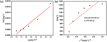 | ||
| Fig. 9 Kinetic characteristics and reaction mechanism of CoNi0.5-MOF/CC electrode: (a) fitting theoretical capacity; (b) fitting theoretical capacitive capacity (Trassatti's method). | ||
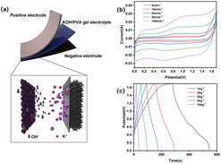
Taking CoNi0.5-MOF/CC as the positive electrode, an asymmetric flexible supercapacitor was assembled, with N-doped graphene (N-Gr) as the negative electrode and KOH/PVA as the gel electrolyte to test the practical application performance of the no-binder CoNi0.5-MOF/CC electrode, as shown in Fig. 10(a). The electrochemical performance was examined by CV, GCD, and EIS in a two-electrode system. Fig. 10(b) shows the CV curves of the asymmetric supercapacitor at different scanning rates. The results show that the capacitor's voltage can reach 1.7 V, which is sufficient to power a number of smart electronic devices. In addition, although the general shape of the CV curves is nearly rectangular during this potential window, there are redox peaks at various scanning rates. It demonstrated that the coexistence of double layer capacitance and pseudo-capacitance is the operating mechanism of the supercapacitor. The device's charge–discharge capability was tested using GCD method at various current densities. Fig. 10 exhibits that the device obtained the specific capacitance of 160.6 F g−1, 156.2 F g−1, 151.2 F g−1, 146.6 F g−1 and 102.5 F g−1at current densities of 1 A g−1, 2 A g−1, 3 A g−1, 5 A g−1, and 10 A g−1 respectively. As the current density increases, the capacitance decreases slightly as the resistance of the capacitor increases and the internal potential increases, leading to an increase in IR drop. In comparison with other devices, however, the assembled device exhibits exceptional rate performance, indicating that the supercapacitor can be charged and discharged effectively at high current density.
To assesses its flexibility, the device underwent bending ranging from 90 to 180 degrees followed by a charge–discharge test to evaluate its performance under bending conditions. Fig. 11(a and b) shows photos of the device, flat and bent. Fig. 11(c and d) compares the GCD curves and EIS impedance spectra measured under bending conditions. Although the voltage does not reach 1.7 V because the contact between electrodes is not as excellent as it is under flat conditions, the device has a high charge–discharge capacity of 125 F g−1 under bending conditions at 1 A g−1 current density, which is a little less than that of the unbent device. The EIS spectrum indicates that the decreased capacitance may attributed to the Rs and Warburg impedance of the electrode material increasing after bending.
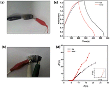 | ||
| Fig. 11 (a and b) Photos of assembled supercapacitor in flat and bent state; (c) GCD performance comparison before and after bending; (d) EIS spectrum. | ||
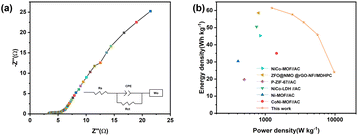
The electrochemical impedance spectrum of the assembled asymmetric supercapacitor device was fitted to further analyze its dynamic characteristics. As depicted in Fig. 12(a), impedance data can be obtained from fitted equivalent circuit models. Table 1 summarizes the corresponding parameter values of the circuit components. The solution resistance (Rs), charge transfer resistance (Rct), double layer capacitance (CPE) and Warburg diffusion resistance comprise the circuit model.
| Device | R s | CPE-P | R ct | Wo–P | Wo–R |
|---|---|---|---|---|---|
| CoNi0.5-MOF/CC//N-Gr | 3.121 Ω | 0.4323 Ω | 2.375 Ω | 0.6825 | 85.78 Ω |
According to the analog equivalent circuit, the device has a small Rs (3.121Ω). W–P is the Warburg diffusion coefficient, and when it is 0.5, it indicates capacitive diffusion. The value obtained after fitting is 0.6825, showing a combination of pseudo-capacitance and double layer capacitance, which is consistent with the asymmetric device structure.
For practical applications, energy density and power density are critical. According to eqn (2) and (3), the CoNi0.5-MOF/CC//N-Gr asymmetric supercapacitor has an energy density of 61.46 W h kg−1 at the power density of 1244.56 W kg−1. The device obtained various energy densities at different power densities, such as 57.64 W h kg−1 at 2444.4 W kg−1, 53.1 W h kg−1 at 3555.1 W kg−1, and 45.83 W h kg−1 at 5625 W kg−1, and even at a high-power density of 9747 W kg−1, it still has an energy density of 24.0667 W h kg−1, showing good rate performance and excellent energy storage characteristics. The Ragone plot in Fig. 12(b) and Table S1† show that this device has superior energy and power density when compared to the asymmetric capacitor devices assembled by other related materials.33–39 The assembled device with high practical energy density and power density shows promising application prospects.
Conclusions
In summary, we have developed a binder-free CoNi0.5-MOF/CC electrode with excellent capacitive properties by in situ growth of CoNi0.5-MOF on CC pretreated with H2O2. This electrode exhibits a notably higher specific capacitance of 1337.5 F g−1 compared to CoNi0.5-MOF (∼578 F g−1) at a current density of 1 A g−1, alongside an excellent rate capability of 88% specific capacitance retention at a current density of 10 A g−1 after 6000 cycles. Moreover, the flexible asymmetric solid-state supercapacitor assembled with CoNi0.5-MOF/CC was used as the positive electrode with nitrogen-doped graphene (N-Gr) as the negative electrode, achieving an energy density of 61.46 W h kg−1 at a power density of 1244.56 W kg−1. Remarkably, it maintains a stable capacitance of ∼125 F g−1 at 1 A g−1 even when subjected to bending, showcasing its significant potential for application in flexible electronics.Author contributions
Weijie Zhang contributed to the conception, design, analysis and writing of the study. Zhen Cao contributed to the design, analysis and writing of the study. Yuying Li contributed to the analysis of the study. Ruiting Li contributed to the analysis of the study. Yanmei Zheng contributed to the analysis of the study. Ping Su contributed to the writing of the study. Xinli Guo contributed to the design, analysis, and writing of the study and provided the funding support.Conflicts of interest
There are no conflicts to declare.Acknowledgements
The authors would like to thank the financial support from the National Natural Science Foundation of China (51574054), the Scientific Research Foundation of Chongqing University of Technology (0101220631), Chongqing Municipal Education Commission (KJZD-K202201107, KJQN202301102), Chongqing Science and Technology Bureau (CSTB2022NSCQ-MSX0356, 2023TIAD-KPX0126), Joint Fund of Chongqing Municipal Education Commission and Science and Technology Bureau (CSTB2022NSCQ-LZX0032) and Professional Experimental Center of Chongqing University of Technology.References
- D. Fu, H. Li, X.-M. Zhang, G. Han, H. Zhou and Y. Chang, Mater. Chem. Phys., 2016, 179, 166–173 CrossRef CAS.
- L. Han, H. Huang, X. Fu, J. Li, Z. Yang, X. Liu, L. Pan and M. Xu, Chem. Eng. J., 2020, 392, 123733 CrossRef CAS.
- X. He, X. Mao, C. Zhang, W. Yang, Y. Zhou, Y. Yang and J. Xu, J. Mater. Sci.: Mater. Electron., 2019, 31, 2145–2152 CrossRef.
- D. P. Dubal, K. Jayaramulu, J. Sunil, Š. Kment, P. Gomez-Romero, C. Narayana, R. Zbořil and R. A. Fischer, Adv. Funct. Mater., 2019, 29, 1900532 CrossRef.
- B. Liu, H. Shioyama, H. Jiang, X. Zhang and Q. Xu, Carbon, 2010, 48, 456–463 CrossRef CAS.
- V. Shrivastav, S. Sundriyal, P. Goel, H. Kaur, S. K. Tuteja, K. Vikrant, K.-H. Kim, U. K. Tiwari and A. Deep, Coord. Chem. Rev., 2019, 393, 48–78 CrossRef CAS.
- D. Ji, H. Zhou, Y. Tong, J. Wang, M. Zhu, T. Chen and A. Yuan, Chem. Eng. J., 2017, 313, 1623–1632 CrossRef CAS.
- H. Jia, Z. Wang, X. Zheng, Y. Cai, J. Lin, H. Liang, J. Qi, J. Cao, J. Feng and W. Fei, Electrochim. Acta, 2019, 312, 54–61 CrossRef CAS.
- A. A. Bhoite, K. V. Patil, R. S. Redekar, P. S. Pati, V. A. Sawant and N. L. Tarwal, J. Solid State Chem., 2023, 326, 124192 CrossRef CAS.
- Y. Xiao, W. Wei, M. Zhang, S. Jiao, Y. Shi and S. Ding, ACS Appl. Energy Mater., 2019, 2(3), 2169–2177 CrossRef CAS.
- W. Xuan, R. Ramachandran, C. Zhao and F. Wan, J. Solid State Electrochem., 2018, 22, 3873–3881 CrossRef CAS.
- H. Zhang, J. Wang, Y. Sun, X. Zhang, H. Yang and B. Lin, J. Alloys Compd., 2021, 879, 160423 CrossRef CAS.
- B. Ramasubramanian, C. Chinglenthoiba, X. Huiqing, N. Xiping, H. K. Hui, S. Valiyaveettil, S. Ramakrishna and V. Chellappan, Surf. Interfaces, 2022, 34, 102397 CrossRef CAS.
- F. Ren, Y. Ji, F. Chen, Y. Qian, J. Tian and J. Wang, Mater. Chem. Front., 2021, 5(19), 7333–7342 RSC.
- X. Hang, J. Zhao, Y. Xue, R. Yang and H. Pang, J. Colloid Interface Sci., 2022, 628, 389–396 CrossRef CAS PubMed.
- W. Zhang, X. Guo, Y. Wang, Y. Zheng, J. Zhao, H. Xie, Z. Zhang and Y. Zhao, Energy Fuels, 2022, 36, 1716–1725 CrossRef CAS.
- H. S. Kim, M. S. Kang and W. C. Yoo, J. Mater. Chem. A, 2019, 7, 5561–5574 RSC.
- G. Li, H. Cai, X. Li, J. Zhang, D. Zhang, Y. Yang and J. Xiong, ACS Appl. Mater. Interfaces, 2019, 11, 37675–37684 CrossRef CAS PubMed.
- S. Li, K. Yang, P. Ye, K. Ma, Z. Zhang and Q. Huang, Appl. Surf. Sci., 2020, 503, 144090 CrossRef CAS.
- S. Xu, R. Liu, X. Shi, Y. Ma, M. Hong, X. Chen, T. Wang, F. Li, N. Hu and Z. Yang, Electrochim. Acta, 2020, 342, 136124 CrossRef CAS.
- J. Ma, J. Li, R. Guo, H. Xu, F. Shi, L. Dang, Z. Liu, J. Sun and Z. Lei, J. Power Sources, 2019, 428, 124–130 CrossRef CAS.
- Y. Liu, J. Liu, Y. Cao, W. Shang, N. Peng, X. Long, S. Zhou and Y. Wen, J. Electrochem. Energy Convers. Storage, 2022, 19, 031002 CrossRef CAS.
- Y. Han, J. Cui, Y. Yu, Y. Chao, D. Li, C. Wang and G. G. Wallace, ChemSusChem, 2022, 15, 202200644 CrossRef PubMed.
- R. Hou, M. Miao, Q. Wang, T. Yue, H. Liu, H. S. Park, K. Qi and B. Y. Xia, Adv. Energy Mater., 2019, 10, 1901892 CrossRef.
- H. Huang, P. He, T. Huang, S. Hu, T. Xu, H. Gu, S. Yang, L. Song, X. Xie and G. Ding, ACS Appl. Mater. Interfaces, 2019, 11, 1239–1246 CrossRef CAS PubMed.
- W. Zhang, Z. Chen, X. Guo, K. Jin, Y. Wang, L. Li and T. Zhang, Electrochim. Acta, 2018, 278, 51–60 CrossRef CAS.
- Y. Zhao, H. Dong, X. He, J. Yu, R. Chen, Q. Liu, J. Liu, H. Zhang, J. Yu and J. Wang, ChemElectroChem, 2019, 6, 3355–3366 CrossRef CAS.
- M. Zhang, D. Hu, Z. Xu, B. Liu, M. Boubeche, Z. Chen, Y. Wang, H. Luo and K. Yan, J. Mater. Sci. Technol., 2021, 72, 172–179 CrossRef CAS.
- Y. Yan, J. Lin, T. Xu, B. Liu, K. Huang, L. Qiao, S. D. Liu and J. Qi, Adv. Energy Mater., 2022, 12(24), 2200434 CrossRef CAS.
- C. Guo, Y. Zhang, M. Yin, J. Shi, W. Zhang, X. Wang, Y. Wu, J. Ma, D. Yuan and C. Jia, J. Power Sources, 2021, 485, 229315 CrossRef CAS.
- F. He, K. Li, S. Cong, H. Yuan, X. Wang, B. Wu, R. Zhang, J. Chu, M. Gong, S. Xiong, Y. Wu and A. Zhou, ACS Appl. Energy Mater., 2021, 4, 7731–7742 CrossRef CAS.
- J. Wang, J. Polleux, J. Lim and B. Dunn, J. Phys. Chem. C, 2007, 111, 14925–14931 CrossRef CAS.
- S. Ardizzone, G. Fregonara and S. Trasatti, Electrochim. Acta, 1990, 35(1), 263–267 CrossRef CAS.
- X. Chu, F. Meng, W. Zhang, H. Yang, X. Zou, S. Molin, P. Jasinski, X. Sun and W. Zheng, Nanotechnology, 2022, 33, 205403 CrossRef CAS PubMed.
- J. Wang, Y. Ma, X. Kang, H. Yang, B. Liu, S. Li, X. Zhang and F. Ran, J. Solid State Chem., 2022, 309, 122994 CrossRef CAS.
- W. Wang, Y. Fang, S. Wang, Z. Zhang, R. Zhao and W. Xue, J. Alloys Compd., 2022, 900, 163532 CrossRef CAS.
- Z. Ma, J. Li, R. Ma, J. He, X. Song, Y. Yu, Y. Quan and G. Wang, New J. Chem., 2022, 46, 7230–7241 RSC.
- J. Acharya, B. Pant, G. P. Ojha and M. Park, J. Colloid Interface Sci., 2022, 610, 863–878 CrossRef CAS PubMed.
- H. Li, X. Wang, L. Dai, F. Guo, H. Mi, C. Ji and L. Sun, Inorg. Chem., 2022, 61, 3866–3874 CrossRef CAS PubMed.
Footnotes |
| † Electronic supplementary information (ESI) available. See DOI: https://doi.org/10.1039/d3nr06225b |
| ‡ The authors contributed equally to this work. |
| This journal is © The Royal Society of Chemistry 2024 |

