 Open Access Article
An ultrathin Li-doped perovskite SEI film with high Li ion flux for a fast charging lithium metal battery†
Ruliang
Liu
 *,
Wenli
Feng
,
Liangzhou
Fang
,
Huiping
Deng
,
Ling
Lin
,
MinChang
Chen
,
Jun-Xing
Zhong
* and
Wei
Yin
School of Chemistry and Materials Science, Guangdong University of Education, Guangzhou 510303, China. E-mail: liuruliang0402@163.com; Zhongjunxing@gdei.edu.cn
First published on 10th October 2024
Abstract
Developing an artificial solid electrolyte interphase (SEI) with high Li ion flux is vital to improve the cycling stability of lithium metal batteries, especially under a high rate. In this work, a novel artificial SEI film was prepared via in situ deposition of a lithium-doped cesium lead chloride perovskite (Li–CsPbCl3). Benefiting from its ultra-high thickness (0.45 μm), high mechanical modulus (5.9 GPa), high lithium-ion migration number (0.57), and unique highly oriented framework, the Li–CsPbCl3 SEI film could promote the rapid transport and uniform deposition of lithium ions, enhancing the stability of lithium deposition and stripping. As a result, Li/Li symmetric cells based on the Li–CsPbCl3 protective film could cycle stably for 1300 hours under high current density of 10 mA cm−2. In addition, the Li/LiFePO4 battery using the Li–CsPbCl3 SEI film showed an impressive cycling stability with a capacity retention rate of up to 91.4% after 230 cycles at a high current rate of 3C.
1. Introduction
The rapid development of electric vehicles calls for lithium-ion batteries with higher energy density and safety.1,2 The energy density of lithium-ion batteries is greatly limited by the lower capacity of the graphite anode (372 mA h g−1). Lithium metal anode has received widespread attention owing to its high capacity (3860 mA h g−1), light density and lowest reduction potential (−3.04 V vs. standard hydrogen electrode).3–5 However, in practical operation, because of uneven lithium plating/stripping during the charging and discharging process, a high number of lithium dendrites appears on the surface of the lithium metal anode, which easily pierce through the separator and lead to serious safety issues.6,7 Moreover, lithium metal is thermodynamically unstable towards organic electrolytes, thus causing low Coulombic efficiency and poor cycling stability of lithium metal batteries.8,9To date, numerous approaches have been devoted to suppressing the uncontrolled growth of lithium dendrites, such as solid-state electrolytes,10–17 functional separators,18–20 and 3D porous lithium hosts.21–23 Because of the low ion conductivity for solid-state electrolytes, a large proportion of inactive components in 3D porous lithium hosts and functional separators, these approaches will seriously damage the rate performance and energy density of lithium metal batteries. Apart from these methods, a method of suppressing lithium dendrites by constructing artificial solid electrolyte interphase (SEI) layers is available.24 Generally, a pristine SEI layer can be naturally formed via side reactions between Li metal and organic electrolytes. Owing to the poor mechanical strength and uniform coverage of a pristine SEI layer, it is still very difficult for the pristine SEI layer to inhibit the growth of lithium dendrites during long-term Li plating/stripping. Moreover, the pristine SEI layer will undergo repeated rupture and growth because of the unavoidable mechanical deformation of lithium metal electrodes, which can consume a large amount of electrolyte and give rise to the poor cycling stability of lithium metal batteries.25,26
Surface coating of Li metal with functional materials, including organic polymers, inorganic non-metallic materials, metal alloys and composite membranes, have been applied to prepare a series of artificial SEI layers, and has been considered an effective strategy for homogeneous Li deposition and long-life LMBs.27–30 For example, Liang et al. reported an interfacial layer through the electrostatic integration of the cationic polymer poly(diallyldimethylammonium chloride) with commercial bamboo fibers (PBFs) to precisely regulate the SEI at the molecular level.31 Wu et al. developed a robust all-organic artificial SEI layer (xPCMS-g-PEGMA). Due to enhanced mechanical robustness, adequate ionic conduction channels, and uniform Li+ diffusion, xPCMS-g-PEGMA achieved a highly efficient and dendrite-free lithium metal anode.32 These artificial SEI layers can separate the lithium metal anode from the electrolyte and exhibit the ability to inhibit Li dendrite growth. However, the liquid electrolyte can still penetrate the entire artificial SEI layer during long cycles, leading to spontaneous side reactions at the interface. More seriously, the incompatibility between structural stability and high ion conductivity, poor interconnectivity at the interface, and a relatively thick surface coating hinder Li plating/stripping, further limiting the capacity and long cycle performance of lithium metal batteries. Therefore, developing novel functional materials with good structural stability and lithium-ion conductivity to construct high-performance ultrathin artificial SEI films remains a huge challenge.
Metal halide perovskite (ABX3, X is a halide) is known as a class of perovskites that consists of corner-sharing BX6 octahedra and AX12 cuboctahedra.33 Due to its adjustable three-dimensional framework structure and bandgap, metal halide perovskites can achieve Li+ conduction and electronic insulation, which is expected to become a promising candidate for constructing a high-performance SEI layer. Recently, Yao et al. reported metal chloride perovskite (MASnCl3 or MAPbCl3) as the artificial SEI layers to stabilize the Li metal anode and achieved the stable cycling of LiCoO2/Li cells.34 Yi et al. developed a fluoride perovskite as an artificial solid electrolyte interface (SEI) to induce uniform lithium deposition for air-stable and dendrite-free lithium metal anode.35 However, under high current density, conventional perovskites can limit the transport efficiency of lithium ions in the lattice and still lead to uneven lithium deposition. Thus, it is very important to designing novel perovskites with high lithium-ion conduction to regulate Li flux in the SEI.
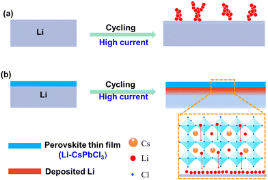
In this work, for the first time, we reported a class of ultrathin Li-doped metal halide perovskite (Li–CsPbCl3) as artificial SEI layers to achieve long-term Li plating/stripping cycling under high current densities. As shown in Fig. 1, benefiting from the tough and dense inorganic components, ordered 3D skeleton structure and abundant pre-embedded lithium ions in the perovskite nanolattice, our Li–CsPbCl3 can significantly enhance the mechanical properties of the membrane, block the infiltration of organic electrolyte solvents, improve the transport efficiency of lithium ions, and homogenize the lithium-ion flow. Furthermore, due to the excellent dispersibility of Li–CsPbCl3 in organic solvents, an ultrathin yet uniform SEI layer based on Li–CsPbCl3 coating was easily obtained via the facile spin coating method. As a result, such Li–CsPbCl3-protected Li anodes enable uniform Li plating/stripping at an ultrahigh current density of 10 mA cm−2 over 1200 h in Li symmetrical cells.
2. Results and discussion
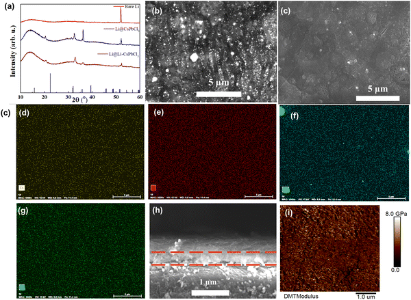
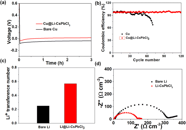
The precursor membrane was firstly prepared by spin-coating the precursor solution mixture on Li metal surface. Then, the in situ formation of the Li–CsPbCl3 SEI layer on Li metal surface could be obtained by the annealing technology. As shown in Fig. 2a, the XRD pattern of the CsPbCl3 sample exhibits several peaks located at 21.3, 32.4, and 35.2°, which is in accordance with the XRD standard card of CsPbCl3. Compared to the CsPbCl3 sample, the characteristic peak of Li–CsPbCl3 shifts to the right at 20°, mainly due to the lattice contraction caused by the doping of lithium ions, resulting in a peak shift towards higher angles. The XRD results indicate the successful preparation of the Li–CsPbCl3 SEI film. Such a highly-oriented crystal structure will be able to accelerate the transport of Li ions throughout the Li–CsPbCl3 SEI film. Scanning electron microscopy (SEM) was further conducted to investigate the morphological features of the artificial SEI. As displayed in Fig. 2b, Li–CsPbCl3 particles were uniformly aggregated on the surface of Li foil, and the resultant Li–CsPbCl3 SEI film shows a dense structure. The unique compact structure is not only able to avoid the permeation of the electrolyte during cycling but also improve the homogeneous deposition of lithium ions. The distribution of Li–CsPbCl3 particles in the Li–CsPbCl3 SEI film coating on Li foil was investigated by energy dispersive X-ray (EDX) mapping (Fig. 2d–g). The result reveals that lithium, cesium, lead, and chlorine elements are homogeneously distributed. Benefiting from such a homogeneous distribution, Li–CsPbCl3 is able to improve the lithium-ion transport efficiency through the SEI. The cross-section SEM image of the Li–CsPbCl3 SEI film shows that the Li–CsPbCl3 layer is tightly bound to Li metal, and the thickness of the SEI film coating is as thin as 0.45 μm, which has significant advantages compared with the recently reported literature (e.g., 5 μm for CNF-g-PSSLi,27 4 μm for xPCMS-g-PEGMA/LN,32 and 5 μm for LiF/Li3Sb-x36). This ultrathin Li–CsPbCl3 SEI film can decrease the interface impedance between the electrolyte and the anode and enhance lithium-ion transport. The mechanical property of the Li–CsPbCl3 SEI film was also investigated by the AFM test. It is worth noting that the average Young's modulus of the Li–CsPbCl3 SEI film is as high as 5.9 GPa (Fig. 2i). Benefiting from the ultrathin thickness and excellent mechanical strength, our ultrathin Li–CsPbCl3 SEI film can effectively avoid a decrease in the energy density of the Li metal batteries and inhibit the growth of lithium dendrites during long-term cycling processes.Fig. 3a displays the galvanostatic voltage profiles of Li deposition on bare Cu and Li–CsPbCl3-coated Cu (Cu@ Li–CsPbCl3) electrodes. The nucleation overpotential of lithium on copper foil modified with Li CsPbCl3 artificial SEI film (Cu@Li–CsPbCl3) is only 18 mV, much lower than the nucleation overpotential of lithium on untreated copper foil (40 mV), indicating that Li–CsPbCl3 has lower Li plating resistance and is beneficial for Li nucleation. The Li plating/stripping behavior of Li/Cu half-cells using Cu@Li–CsPbCl3 and bare Cu electrode was measured at a capacity of 1 mA h cm−2 and 1 mA cm−2. As displayed in Fig. 3b, it was found that Li/Cu half-cells with Cu@Li–CsPbCl3 can cycle for 120 cycles with a high average Coulombic efficiency (CE) of 98.7%. In sharp contrast, the CE of the Li/Cu half cells with bare Cu begins to decline after only 30 cycles and rapidly decreases after 58 cycles, which obtains a lower average CE of 85.6%. It is worth noting that such a high average CE is comparable to that of previous asymmetric Li/Cu cells (e.g., 96% for ND, 94.7% for OPEs).37–40 This result indicates that our artificial Li–CsPbCl3SEI film can suppress the parasitic side reactions between the lithium metal anode and electrolyte, achieving efficient lithium deposition and stripping. To investigate the lithium ion conducting ability of the Li–CsPbCl3 SEI film, the lithium-ion transference number (tLi+) was measured via the chronoamperometry profiles and EIS of Li/Li symmetric cells. According to the calculations, the lithium-ion migration number of the Li–CsPbCl3 SEI film is up to 0.57, significantly higher than that of the polyolefin membrane (0.26), indicating that the Li–CsPbCl3 artificial SEI film has lithium single ion transport characteristics, which is beneficial for reducing the concentration gradient of lithium ions and enhancing the uniform deposition of lithium ions. Furthermore, the interface impedance of the Li/Li symmetric cell with the artificial Li–CsPbCl3 SEI film is only 158 Ω much lower than that of the Li/Li symmetric cell with bare Li (315 Ω), demonstrating that the Li–CsPbCl3 artificial SEI film significantly improves the transport kinetics of lithium ions at the interface. Benefiting from its unique physical and chemical properties, the Li–CsPbCl3 artificial SEI film can upregulate the transport and deposition behavior of lithium ions at the molecular level, which is thereby expected to limit the growth of lithium dendrites.
To evaluate their cycling stability during the lithium plating/stripping process, Li/Li symmetric cells with bare Li, CsPbCl3 film and Li–CsPbCl3 film were assembled and tested by galvanostatic cycling. Under the condition of a low current density of 1 mA cm−2, the cycling lifespan of Li/Li symmetric cells using bare Li and Li@CsPbCl3 only hold on remains 620 h and 900 h, respectively. As a comparison, the Li/Li symmetric cell with the Li–CsPbCl3 SEI film shows a tremendously prolonged lifetime of 1100 h cycles. The EIS of the Li/Li symmetric cell with the Li–CsPbCl3 SEI film during cycling was investigated. As the number of cycles increases, the interface impedance gradually decreases and stabilizes at 70 Ω after 50 cycles, indicating that the Li–CsPbCl3 SEI film could promote the interface stability between the electrolyte and electrode during cycling (Fig. S2, ESI†). When the current density is increased to 5 mA h cm−2, the Li@Li–CsPbCl3/Li@Li–CsPbCl3 symmetric cell still exhibits excellent stability of Li plating/stripping, and the cycling lifetime is up to 1200 h. In sharp contrast, the Li/Li symmetric cell shows substantially larger overpotentials with severely fluctuating voltage profiles and shorter cycling lifetime (180 h). The test current density is further increased to 10 mA cm−2; the Li@Li–CsPbCl3/Li@Li–CsPbCl3 symmetric cell displays a very stable voltage plateau even after long-time cycling for over 1300 h. By comparison, the Li/Li symmetric cell using bare Li anode exhibits much poor cycling stability (failed within only 150 h) with larger overpotentials and severely fluctuating voltage profiles at high current densities. More importantly, most of the reported artificial SEI films still suffer from low current density (≤5 mA cm−2). Therefore, our Li–CsPbCl3 SEI film shows great advantage in the endurance of ultrahigh current density.
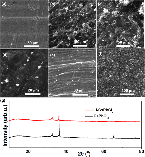
In order to investigate the inhibitory effect of the Li–CsPbCl3 SEI film on lithium dendrites and its electrochemical stability, SEM was performed to examine the lithium metal surface morphology changes of the Li/Li symmetric cells before and after cycling. As shown in Fig. 4, the surface of pristine lithium metal is observed to be smooth and dense. After 100 cycles at a current density of 5 mA h cm−2, the surface of the cycled lithium foil becomes uneven with a large number of moss-like particles appearing, indicating the uncontrolled growth of dendrites. However, after cycling the Li@Li–CsPbCl3/Li@Li–CsPbCl3 symmetric cell under the same conditions, the lithium metal surface still remains smooth, indicating that the lithium-doped perovskite SEI film can effectively inhibit the growth of lithium dendrites. In addition, for the Li@Li–CsPbCl3/Li@Li–CsPbCl3 symmetric cell, the morphology of the Li–CsPbCl3 film coated on the lithium metal surface does not show significant changes before and after cycling, indicating that the Li–CsPbCl3 SEI film has good electrochemical stability. On the other hand, the XRD characterization of the Li@Li–CsPbCl3 electrode from the Li@Li–CsPbCl3/Li@Li–CsPbCl3 symmetric cells before and after the cycles is also conducted. As shown in Fig. 5g, the characteristic diffraction peaks of Li@CsPbCl3 and the Li@Li–CsPbCl3 electrode before and after cycling did not show significant changes, further demonstrating the high electrochemical stability of Li–CsPbCl3. Compared with the Li@Li–CsPbCl3 film, the peak value of lithium from Li@CsPbCl3 is weaker, which may be attributed to the loss of lithium ions in the SEI film during battery charging and discharging. The XRD results indicate that the lithium-doped perovskite SEI film can be beneficial for accelerating the transport of lithium ions.
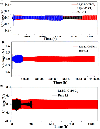 | ||
| Fig. 4 Voltage–time curves of Li/Li and Li@Li–CsPbCl3/Li@Li–CsPbCl3 symmetric cells with an areal capacity of 1 mAh cm−2 at a current density of (a) 1 mA cm−2, (b) 5 mA cm−2, and (c) 10 mA cm−2. | ||
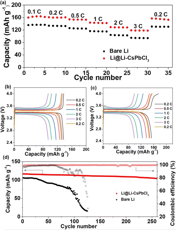
Given the excellent cycling stability of the artificial Li–CsPbCl3 SEI film in Li/Li symmetric cells, Li/LiFePO4 full cells with bare Li and Li@Li–CsPbCl3 electrode were assembled to investigate the practical application potential of the artificial Li–CsPbCl3 SEI film. As shown in Fig. 6a, as the current density increases, the Li/LiFePO4 full cell using the Li@Li–CsPbCl3 electrode can still deliver high discharge capacities of 162.7, 160.5, 153.8, 143.1, 128.8, and 118.6 mA h g−1 at 0.1, 0.2, 0.5, 1, 2 and 3C, respectively. However, the cell with a bare Li anode displays much inferior rate performance; the discharge specific capacities are 136.7, 133.5, 125.3, 116, 103.6 and 94.6 mA h g−1 at 0.1, 0.2, 0.5, 1, 2 and 3C, respectively. The corresponding charge–discharge profiles at these different rates are presented in Fig. 6b and c. Compared with bare Li electrode, the Li@Li–CsPbCl3 electrode has a much lower and more stable polarization voltage. In addition, the long cycling performance of Li/LiFePO4 cells with bare Li and Li@Li–CsPbCl3 electrode at a high current density of 3C is shown in Fig. 6d. The Li@Li–CsPbCl3/LiFePO4 cell presents an impressive cycling stability with a high-capacity retention of 91.4%, and the specific capacity is still up to 106.8 mA h g−1 at the 230th cycle. In sharp contrast, the specific capacity of the Li/LiFePO4 cell is as low as 16 mA h g−1 at the 200th cycle with a low-capacity retention of 15.1%. These results demonstrate that our ultrathin Li–CsPbCl3 SEI film can obviously enhance the electrochemical performance of the Li/LiFePO4 full cell, which could be attributed to the homogenous Li+ flux and several fast transmission channels enabled by the 3D nanonetwork skeleton with a highly oriented crystal structure.
3. Conclusion
In summary, we propose a promising approach to inhibit the uncontrollable growth of lithium dendrites by preparing the lithium-doped perovskite (Li–CsPbCl3) artificial layer. Due to its ultra-high thickness, high mechanical modulus, high lithium-ion migration number, and highly oriented framework, Li–CsPbCl3 was successfully employed as the artificial SEI layer. It not only effectively suppresses the growth of lithium dendrites but also enhances the transport of lithium ions at the interface and induces the ultra-dense and uniform deposition of Li, providing a favorable environment for stable Li electroplating/stripping and significantly improving the electrochemical performance of lithium metal batteries. This work provides an effective strategy in the rational design of novel high-performance lithium-doped perovskite SEI layers with special ultrathin thickness and ion-selective channels.4. Experimental section
4.1. Fabrication of Li–CsPbCl3 SEI films
50.5 mg of cesium chloride ((CsCl, 99%, Aladdin)) and 83.4 mg of lead chloride (PbCl2, 99.9%, Aladdin) were added in DMSO (99.9%, Aladdin) and 0.6 mg lithium chloride (LiCl, 99%, Aladdin). The mixture was stirred and completely dissolved at 90 °C for 5 hours to form the Li–CsPbCl3 precursor solution with a concentration of 0.05 M. 100 μL of dimethyl sulfoxide solvent (DMSO, 99%, Aladdin) was firstly dripped on the lithium metal foil and spin-coated at 2000 rpm for 30 s. Then, 100 μL of Li–CsPbCl3 precursor solution was dripped on the lithium metal foil and spin-coated at 2000 rpm for 60 s. The deposited film was immediately annealed on a hot plate at 100 °C for 30 min to remove the solvent. Finally, the Li@Li–CsPbCl3 electrode was fabricated and prepared for the following battery assembly. The Li@CsPbCl3 electrode was prepared according to the above method, except that LiCl was not added. All the CsPbCl3 and Li–CsPbCl3 SEI films and corresponding electrodes were fabricated and stored in an argon-filled glove box with O2 < 0.5 ppm and H2O < 0.1 ppm.4.2. Battery assembly and test
LiFePO4 (LFP, 99%, Kelude), poly(vinylidene fluoride) (PVDF, 98%, Sigma) and conductive graphite (99%, Kelude) were mixed in an agate mortar according to the mass ratio of 8![[thin space (1/6-em)]](https://www.rsc.org/images/entities/char_2009.gif) :
:![[thin space (1/6-em)]](https://www.rsc.org/images/entities/char_2009.gif) 1
1![[thin space (1/6-em)]](https://www.rsc.org/images/entities/char_2009.gif) :
:![[thin space (1/6-em)]](https://www.rsc.org/images/entities/char_2009.gif) 1. NMP was added dropwise to obtain a homogenous slurry by grinding for 1 h. Finally, the slurry was coated on a carbon-coated aluminum foil. After drying, it was tailored into round disks with a 12 mm diameter, and the LFP loading was about 2.6 mg cm−2. Li/Li cells, Li/Li symmetric cells and Li/LFP cells were assembled using CR2032 coin cells in an argon-filled glove box. (O2 < 0.5 ppm, H2O < 0.1 ppm). The ether electrolyte was 1.0 M LiTFSI in 1,2-dimethoxyethaneDME/1,3-dioxolane DOL (1/1, v/v) with 1 wt% LiNO3 additive (LS-002, Suzhou Duoduo Chemical Technology Co., Ltd, China) for Li/Li symmetric cells and Li/Cu cells. The ester electrolyte was 1.0 M LiPF6 in ethylene carbonate/diethyl carbonate (1/1, v/v) (LB-008, Suzhou Duoduo Chemical Technology Co., Ltd, China) for Li/LFP cells.
1. NMP was added dropwise to obtain a homogenous slurry by grinding for 1 h. Finally, the slurry was coated on a carbon-coated aluminum foil. After drying, it was tailored into round disks with a 12 mm diameter, and the LFP loading was about 2.6 mg cm−2. Li/Li cells, Li/Li symmetric cells and Li/LFP cells were assembled using CR2032 coin cells in an argon-filled glove box. (O2 < 0.5 ppm, H2O < 0.1 ppm). The ether electrolyte was 1.0 M LiTFSI in 1,2-dimethoxyethaneDME/1,3-dioxolane DOL (1/1, v/v) with 1 wt% LiNO3 additive (LS-002, Suzhou Duoduo Chemical Technology Co., Ltd, China) for Li/Li symmetric cells and Li/Cu cells. The ester electrolyte was 1.0 M LiPF6 in ethylene carbonate/diethyl carbonate (1/1, v/v) (LB-008, Suzhou Duoduo Chemical Technology Co., Ltd, China) for Li/LFP cells.
The electrochemical performances of the Li/Cu cells, symmetric Li/Li cells and Li/LiFePO4 cells were measured by a NEWARE Battery Test System (Shenzhen Neware Electronics Co., Ltd, Shenzhen, China).
4.3. Characterization
The morphology and microstructure of the samples were investigated by field-emission scanning electron microscopy (SEM, TESCAN MIRA LMU, Brno, Czech Republic). X-ray diffraction (XRD, Bruker, Billerica, MA, USA) patterns were achieved with a D-MAX 2200 VPC X-ray diffractometer with Ni-filtered Cu/K-α radiation at a scan rate of 10° min−1 from 10° to 80°. Atomic force microscopy (AFM) Young's modulus images of the separators were recorded on an atomic force microscope (Dimension Fast Scan, Bruker) in peak force quantitative nano-mechanics mode. Electrochemical impedance spectroscopy (EIS) was carried out using an electrochemical workstation (Coster CS350, Wuhan, China). EIS was carried out at an AC voltage amplitude of 5 mV between 100 kHz and 0.1 Hz. The galvanostatic charge–discharge test was carried out using the NEWARE Battery Test System (Shenzhen Neware Electronics Co., Ltd, Shenzhen, China) in the voltage range of 2.5–4 V (vs. Li/Li+) with the calculated C-rate based on the theoretical capacity value of LFP (170 mA g−1). The cycled electrodes were gently washed in dimethyl carbonate (DMC) to remove electrolyte salt residue and dried in a glove box.Li+ transference number (tLi+) was calculated based on the following eqn (1)
 | (1) |
Author contributions
Ruliang Liu and Jun-Xing Zhong conceived the idea and were responsible for drafting and editing the manuscript. Wenli Feng, Liangzhou Fang, and Huiping Deng conducted most of the device fabrication, measurements, and characterizations. Ling Lin and Min-Chang Chen were responsible for data analysis and visualization. Wei Yin took charge of writing-review.Data availability
The data supporting this article have been included as part of the ESI.†Conflicts of interest
The authors declare no conflict of interest.Acknowledgements
This work was supported by Undergraduate Innovation and Entrepreneurship Training Plan of Guangdong Province (S202314278035), Basic and Applied Basic Research Fund Project of Guangdong (2022A1515011778, 2023A1515030160), Key Scientific Research Projects of General Universities in Guangdong Province (2023KTSCX095), Research and Innovation Group of Guangdong University of Education (2024KYCXTD014) and Guangdong University of Education-Guangzhou Yuntong Lithium Battery Co., Ltd. Lithium-ion battery university-enterprise joint laboratory project (No. XQSYS-2222873).References
- V. Thangadurai, S. Narayanan and D. Pinzaru, Chem. Soc. Rev., 2014, 43, 4714–4727 RSC.
- D. Lin, Y. Liu and Y. Cui, Nat. Nanotechnol., 2017, 12, 194–206 CrossRef CAS.
- X. Fan and C. Wang, Chem. Soc. Rev., 2021, 50, 10486–10566 RSC.
- T. Wang, W. Luo and Y. Huang, Acc. Chem. Res., 2023, 56, 667–676 CrossRef CAS.
- Y. Xu, K. Dong, Y. Jie, P. Adelhelm, Y. Chen, L. Xu, P. Yu, J. Kim, Z. Kochovski, Z. Yu, W. Li, J. LeBeau, Y. Shao-Horn, R. Cao, S. Jiao, T. Cheng, I. Manke and Y. Lu, Adv. Energy Mater., 2022, 12, 2200398 CrossRef.
- J. Fu, P. Yu, N. Zhang, G. Ren, S. Zheng, W. Huang, X. Long, H. Li and X. Liu, Energy Environ. Sci., 2019, 12, 1404–1412 RSC.
- F. Wu, Y.-X. Yuan, X.-B. Cheng, Y. Bai, Y. Li, C. Wu and Q. Zhang, Energy Storage Mater., 2018, 15, 148–170 CrossRef.
- J. Wang, B. Ge, H. Li, M. Yang, J. Wang, D. Liu, C. Fernandez, X. Chen and Q. Peng, Chem. Eng. J., 2021, 420, 129739 CrossRef CAS.
- S.-J. Yang, J.-K. Hu, F.-N. Jiang, H. Yuan, H. S. Park and J.-Q. Huang, InfoMat, 2024, 6, e12512 CrossRef CAS.
- M. Zhou, R. Liu, D. Jia, Y. Cui, Q. Liu, S. Liu and D. Wu, Adv. Mater., 2021, 33, 2100943 CrossRef CAS.
- Y. Cui, G. Yu, R. Liu, D. Miao and D. Wu, Chin. J. Chem., 2023, 41, 2848–2854 CrossRef CAS.
- A. Kim, K. Song, M. Avdeev and B. Kang, ACS Energy Lett., 2024, 9, 1976–1983 CrossRef CAS.
- S. H. Choi, W.-J. Kim, B.-H. Lee, S.-C. Kim, J. G. Kang and D.-W. Kim, J. Mater. Chem. A, 2023, 11, 14690–14704 RSC.
- W. Guo, Q. Liu, K. Wu, X. Hu, X. Liu, X. Cheng, C. Han, Y.-B. He, F. Kang and B. Li, Energy Storage Mater., 2023, 63, 103006 CrossRef.
- K. Wu, A. Li, J. Tan, F. Zhou, H. Yan, P. Wang, T. Xie, Q. Zeng, C. Han, Q. Liu and B. Li, Angew. Chem., Int. Ed., 2024, 63, 202410347 Search PubMed.
- Q. Liu, D. Zhou, D. Shanmukaraj, P. Li, F. Kang, B. Li, M. Armand and G. Wang, ACS Energy Lett., 2020, 5, 1456–1464 CrossRef CAS.
- P. Jaumaux, Q. Liu, D. Zhou, X. Xu, T. Wang, Y. Wang, F. Kang, B. Li and G. Wang, Angew. Chem., Int. Ed., 2020, 59, 9134–9142 CrossRef CAS PubMed.
- Q. Liu, R. Liu, Y. Cui, M. Zhou, J. Zeng, B. Zheng, S. Liu, Y. Zhu and D. Wu, Adv. Mater., 2022, 34, 2108437 CrossRef CAS.
- Y. Wen, J. Ding, J. Liu, M. Zhu and R. Hu, Energy Environ. Sci., 2023, 16, 2957–2967 RSC.
- Y. Hu, C. Wang, Y. Wu, Q. Zhao, A. Li, Q. Zhang, J. Liu, Y. Jin and H. Wang, J. Mater. Chem. A, 2023, 11, 12052–12061 RSC.
- S. Cho, D. Y. Kim, J.-I. Lee, J. Kang, H. Lee, G. Kim, D.-H. Seo and S. Park, Adv. Funct. Mater., 2022, 32, 2208629 CrossRef CAS.
- W. Guan, Y. Lv, C. Ma, Q. Zhang, A. Wei and X. Liu, Mater. Chem. Front., 2023, 7, 315–324 RSC.
- W. Wu, D. Ning, J. Zhang, G. Liu, L. Zeng, H. Yao, M. Wang, L. Deng and L. Yao, Energy Storage Mater., 2023, 63, 102974 CrossRef.
- Y. Wu, C. Wang, C. Wang, Y. Zhang, J. Liu, Y. Jin, H. Wang and Q. Zhang, Mater. Horiz., 2024, 11, 388–407 RSC.
- O. B. Chae and B. L. Lucht, Adv. Energy Mater., 2023, 13, 2203791 CrossRef CAS.
- X. Shen, R. Zhang, X. Chen, X.-B. Cheng, X. Li and Q. Zhang, Adv. Energy Mater., 2020, 10, 1903645 CrossRef CAS.
- Z. Junkui, L. Qiantong, J. Danyang, L. Ruliang, L. Shaohong, Z. Bingna, Z. Youlong, F. Ruowen and W. Dingcai, Energy Storage Mater., 2021, 41, 697–702 CrossRef.
- J. Ben and P. Mauro, Joule, 2023, 7(10), 2228–2244 CrossRef.
- C. Li, Z. Liang, Z. Li, D. Cao, D. Zuo, J. Chang, J. Wang, Y. Deng, K. Liu, X. Kong and J. Wan, Nano Lett., 2023, 23(9), 4014–4022 CrossRef CAS.
- X. Jin, G. Huang, X. Zhao, G. Chen, M. Guan and Y. Li, Energy Adv., 2023, 2, 725–732 RSC.
- Z. Ju, C. Jin, X. Cai, O. Sheng, J. Wang, J. Luo, H. Yuan, G. Lu, X. Tao and Z. Liang, ACS Energy Lett., 2023, 8, 486–493 CrossRef CAS.
- S. Li, J. Huang, Y. Cui, S. Liu, Z. Chen, W. Huang, C. Li, R. Liu, R. Fu and D. Wu, Nat. Nanotechnol., 2022, 17, 613–621 CrossRef CAS.
- S. Shi, Y. Li, X. Li and H. Wang, Mater. Horiz., 2015, 2, 378–405 RSC.
- Y.-C. Yin, Q. Wang, J.-T. Yang, F. Li, G. Zhang, C.-H. Jiang, H.-S. Mo, J.-S. Yao, K.-H. Wang, F. Zhou, H.-X. Ju and H.-B. Yao, Nat. Commun., 2020, 11, 1761 CrossRef CAS.
- Y. Zhang, Y. Liu, J. Zhou, D. Wang, L. Tan and C. Yi, Chem. Eng. J., 2022, 431, 134266 CrossRef CAS.
- A. Hu, W. Chen, X. Du, Y. Hu, T. Lei, H. Wang, L. Xue, Y. Li, H. Sun, Y. Yan, J. Long, C. Shu, J. Zhu, B. Li, X. Wang and J. Xiong, Energy Environ. Sci., 2021, 14, 4115–4124 RSC.
- X.-B. Cheng, M.-Q. Zhao, C. Chen, A. Pentecost, K. Maleski, T. Mathis, X.-Q. Zhang, Q. Zhang, J. Jiang and Y. Gogotsi, Nat. Commun., 2017, 8, 336 CrossRef PubMed.
- C. Yan, X.-B. Cheng, Y.-X. Yao, X. Shen, B.-Q. Li, W.-J. Li, R. Zhang, J.-Q. Huang, H. Li and Q. Zhang, Adv. Mater., 2018, 30, 1804461 CrossRef PubMed.
- S.-J. Tan, J. Yue, X.-C. Hu, Z.-Z. Shen, W.-P. Wang, J.-Y. Li, T.-T. Zuo, H. Duan, Y. Xiao, Y.-X. Yin, R. Wen and Y.-G. Guo, Angew. Chem., Int. Ed., 2019, 58, 7802–7807 CrossRef CAS.
- P. Shi, X.-Q. Zhang, X. Shen, B.-Q. Li, R. Zhang, L.-P. Hou and Q. Zhang, Adv. Funct. Mater., 2021, 31, 2004189 CrossRef CAS.
Footnote |
| † Electronic supplementary information (ESI) available. See DOI: https://doi.org/10.1039/d4ya00507d |
| This journal is © The Royal Society of Chemistry 2024 |

