 Open Access Article
Creative Commons Attribution 3.0 Unported Licence
Vat photopolymerization of tantalum-doped Li7La3Zr2O12 electrolytes: a new Frontier in solid-state battery design†
Diwakar
Karuppiah
ab,
Dmitrii
Komissarenko
a,
Tamanna
Thakur
 a,
Nur Sena
Yüzbasi
a,
Frank
Clemens
a,
Elias
Reisacher
c,
Pinar
Kaya
c,
James
Pikul
b and
Gurdial
Blugan
*a
a,
Nur Sena
Yüzbasi
a,
Frank
Clemens
a,
Elias
Reisacher
c,
Pinar
Kaya
c,
James
Pikul
b and
Gurdial
Blugan
*a
aLaboratory for High Performance Ceramics, Empa, Swiss Federal Laboratories for Materials Science and Technology, Überlandstrasse 129, 8600, Dübendorf, Switzerland. E-mail: gurdial.blugan@empa.ch
bDepartment of Mechanical Engineering, University of Wisconsin Madison, 53705, USA
cMaterials Research Institute Aalen (IMFAA), Aalen University of Applied Sciences, Beethovenstraße 1, 73430 Aalen, Germany
First published on 1st November 2024
Abstract
The advancement of all-solid-state lithium batteries (ASSLBs) necessitates the development of high-performance solid electrolytes that can meet stringent requirements for ionic conductivity, chemical stability, and structural integrity. This study focuses on the design and fabrication of 3D-customized ceramic-based solid electrolytes using Vat Photopolymerization (VPP) 3D printing, with a specific emphasis on tantalum-doped Li7La3Zr2O12 (LLZO). LLZO, known for its superior ionic conductivity, chemical stability, and inherent safety, is an ideal candidate for next-generation battery technologies. The 3D-printed tantalum-doped LLZO electrolytes were engineered to integrate a porous structure for facilitating lithium-ion transport and a non-porous structure to ensure effective ion conduction and mechanical stability. Through the optimization of debinding and sintering processes, the printed electrolytes achieved high density and a refined microstructure, critical factors for enhancing electrochemical performance. Structural and morphological analyses using X-ray diffraction (XRD) and scanning electron microscopy (SEM) confirmed phase purity and detailed microstructural features, respectively. Electrochemical impedance spectroscopy (EIS) demonstrated a significant ionic conductivity of 3.15 × 10⁻⁵ S cm−1, highlighting the potential of these materials for deployment in high-performance ASSLBs. The results underscore the feasibility of VPP 3D printing as a transformative approach for fabricating complex, high-performance solid electrolytes tailored to the demanding specifications of next-generation energy storage systems.
1 Introduction
Following their commercialization in the 1990s, lithium-ion batteries (LIBs) have developed into an essential pillar of modern society.1 They play a vital role in providing energy to a diverse spectrum of devices, ranging from portable electronics to space satellites. Ongoing research efforts are focused on substituting the liquid electrolytes in LIBs, with safer alternatives.2–4 Solid electrolytes based on polymers5 and ceramics6 are being incorporated into batteries to replace the liquid electrolytes. Ceramic electrolytes can potentially improve battery safety compared to polymer electrolytes due to their high temperature stability and wide electrochemical windows. For example, Li7La3Zr2O12 (LLZO) is promising ceramic electrolyte with good ionic conductivity and a wide electrochemical window from 2.5 to 5.0 V vs. Li/Li+.7Many conventional methods are commonly utilized in fabricating layered LLZO electrolytes, including tape casting,8 screen printing,7 sputtering, and other deposition techniques.9 These methods hold promise for yielding materials with robust strength and density, thereby enhancing ionic conductivity. However, the planar structure of these electrolytes may lead to high interfacial impedance and limit the battery kinetics. Achieving uniform solid–solid point contact between electrolyte and electrodes poses challenges, often necessitating additional applied force. Moreover, manufacturing ceramic electrolytes with customized designs is complex due to material rigidity and brittleness. To address these issues, one approach involves fabricating LLZO cells with both porous and dense layers. The porous layer enhances interfacial contact, potentially mitigating impedance concerns. Additive manufacturing of solid electrolytes offers a solution by enabling tailored non-polar designs and integrated porous-dense structures, thereby increasing interfacial contact area.
3D printing offers numerous advantages in battery manufacturing, such as the precise creation of complex internal structures, reduced material waste, a wide range of feedstock options, and simplified cell fabrication processes.10 Depending on the requirements, various techniques such as direct ink writing (DIW),11 ink-jet printing,12 aerosol jet printing,13 fused deposition modeling (FDM),14 stereolithography (SLA),15 and digital light processing (DLP)16 can be utilized. While these methods are predominantly used for polymer-based electrolytes, the application of 3D printing in ceramic electrolytes remains somewhat limited due to the complex nature of material processing.17 For instance, Eric D. Wachsman et al.18 developed a 3D printed cell based on the ceramic solid electrolyte LLZO via DIW. They employed two different inks to print LLZO ceramics onto a conventionally prepared tape-casted LLZO substrate. After the printing process, the binder was thermally decomposed from the printed structure. The tape-casted dense LLZO substrate served as a solid electrolyte, while the 3D printed structure on the substrate acted as a host for electrode infusion. This configuration enabled enhanced areal contact at the electrolyte/electrode interface, resulting in increased conductivity using 3D printing. Our aim is to integrate all these elements together to create a structure that incorporates porous and dense regions effectively, thus leveraging the benefits of both porous and dense structures to enhance the overall performance of the cell.
Valera-Jiménez et al. successfully demonstrated the application of 3D printing in producing ceramic materials for lithium battery components, specifically for the anode LTO (Li4Ti5O12) and LCO (LiCoO2), using fused filament fabrication.19 During the debinding process, the pyrolysis of binder led to the formation of carbon, which acted as a conductive network that enhanced the conductivity of LCO cathode. Additionally, another ceramic self-supported solid electrolyte Li1+xAlxGe2−x(PO4)3 (LAGP) was effectively printed using SLA.20 Among various printing technologies, SLA is an attractive candidate due its capability to achieve a significant solid concentration (40–60 vol%) in ceramic slurries, thereby potentially reducing deformation during the debinding process. Despite a growing interest in additive manufacturing of materials for batteries there is still insufficient information on 3D printing of LLZO solid electrolytes using VAT polymerization techniques. Even though components fabricated via SLA or DLP have potentially superior resolution and surface finishing compared to alternative methods, such as FDM or DIW, there remains a gap in understanding this specific application.21
This article explores the feasibility of using DLP 3D printing to fabricate Ta-doped Li7La3Zr2O12 electrolytes. Tantalum (Ta) is incorporated to improve the conductivity and stability of lithium lanthanum zirconate (LLZO). The addition of Ta as a dopant promotes the formation of a dense grain boundary structure by stabilizing the cubic phase, enhancing both ionic conductivity and mechanical strength.22 Throughout the printing process, various unconventional phenomena were observed, including interactions among ceramic fillers, binders, and photo-initiators, as well as remarkably swift decomposition of organic components during debinding. However, by carefully selecting feedstock and optimizing debinding methods, we successfully printed LLZO electrolytes with high phase purity, relatively high density, and minimal microstructural defects. This paves the way for the development of a new generation of fully printable all-solid-state 3D LLZO batteries using DLP technology.
2 Experimental
2.1 Raw materials and slurry preparation
Ta-doped Li7La3Zr2O12 was developed via solid-state synthesis method. Dried La2(CO3)3, Li2CO3, Ta2O5 (0.4 mol) and m-ZrO2 powders were mixed based on the stoichiometric ratio using planetary ball milling (300 rpm) in isopropanol for 2 h.23 Subsequently, the mixture was annealed at 950 °C for 6 h in air.In this study, a UV-curable binder system was utilized, consisting of 1,6-hexanediol diacrylate (HDDA) and polyethylene glycol diacrylate 250 (PEGDA 250), both sourced from Sigma Aldrich. To stabilize ceramic particles within a low-polar organic medium, the hyperbranched polymer Disperbyk 2152 (BYK Instruments & Measurements, Germany) was employed as a dispersant. Two types of photo-initiators were used to initiate the photo-polymerization reaction: ethyl phenyl(2,4,6-trimethylbenzoyl) phosphinate (TPO-L) and 2-hydroxy-2-methyl-1-phenylpropanone (Igracure 1173), obtained from Rahn AG. To prepare the UV-curable slurry, dried LLZO powder was gradually added to a mixture of acrylic monomers and dispersant. This mixture was then milled in a planetary ball mill for 30 min at 300 rpm until the desired solid content was achieved. Zirconia beads, with a diameter of 3 mm and added in a 1![[thin space (1/6-em)]](https://www.rsc.org/images/entities/char_2009.gif) :
:![[thin space (1/6-em)]](https://www.rsc.org/images/entities/char_2009.gif) 1 ratio relative to the powder weight, were used to break down any aggregates. After each milling session, air was removed from the slurry via vacuum pumping. The photo initiator was incorporated into the slurry at the final stage of the process, and the mixture was left on a rolling bench overnight to enhance its homogeneity.
1 ratio relative to the powder weight, were used to break down any aggregates. After each milling session, air was removed from the slurry via vacuum pumping. The photo initiator was incorporated into the slurry at the final stage of the process, and the mixture was left on a rolling bench overnight to enhance its homogeneity.
2.2 Fabrication of 3D parts
The 3D components were fabricated using a lithography-based DLP printer, the CeraFab 7500 (Lithoz GmbH, Austria) equipped with UV-light source emitting at a wavelength of 365 nm. Operating on a bottom-up methodology, the printer projects light through the bottom of a transparent vat filled with UV-curable slurry. The CeraFab machine incorporates a precise dispenser system capable of uniformly distributing slurry layers atop the vat, facilitating precise control over thickness, even with highly viscous slurries. The vat was filled to achieve a slurry thickness of approximately 175 μm, while the printing layer thickness was set at 10 mm. Shrinkage compensation in the X, Y, and Z axes was established at 1 (−). In the printing process using LLZO slurries, the projector's power density was maintained at 18 mW cm−2, with exposure time ranging from 1 to 16 s. Upon completion of the printing process, the parts were cleaned using a propylene carbonate solution.2.3 Characterizations
The synthesized powder was subjected to phase analysis using a PANalytical X'Pert powder diffractometer from the Netherlands. The specific surface area (SSA) was determined through the Brunauer–Emmett–Teller (BET) method with a Belsorp Microtrac Mini X at −195.8 °C, after heating the powder overnight at 200 °C under vacuum to remove absorbed moisture. Particle size distribution (PSD) was analyzed by laser diffraction using a Beckman Coulter LS13320 system, following a 5 min ultrasonic treatment in isopropanol (IPA). Rheological properties of the suspensions were examined with the Anton Paar rheometer MCR 302, equipped with a coaxial cylinder geometry, measuring viscosity across a shear rate range of 0.1–100 s−1 at a constant temperature of 25 °C. Cure depths of the slurries were determined by polymerizing a thin layer of the suspensions. The suspension was placed in the printer vat and exposed to UV light with a power density of 18 mW cm−2 for various durations. The solidified films were cleaned with isopropanol, and their thickness was measured with a calibrated digital micrometer at multiple points. Films cured at different times (1–30 s) were used to generate a cure depth curve. Thermal analysis was performed using a DSC/TGA instrument (STA 449 F3 Jupiter, Netzsch GmbH, Germany) with a constant heating rate of 5 K min−1 from room temperature up to 550 °C and a synthetic air, nitrogen and argon flow rate of 70 ml min−1. To investigate the activation energy of the binder decomposition, different heating rates and an argon flow rate of 70 ml min−1 were used.24 Based on the Friedman kinetic analysis,25 the critical temperature range for the binder removal process was identified. In this range, different debinding profiles were studied to avoid cracks, pores or blisters during the removal of the organic binder components. Scanning electron microscopy (SEM) images of the sintered parts were captured with a Vega 3 microscope (Tescan, Czech Republic) at an accelerating voltage of 10 kV. Conductivity measurements were carried out using electrochemical impedance spectroscopy (EIS) in a climate chamber (CTS Clima Temperatur Systeme type T-40/200, Hechingen, Germany), applying an alternating voltage of 10 mV over a frequency range from 7 MHz to 1 Hz with a potentiostat (VSP-300, Bio-Logic, Seyssinet-Pariset, France). EIS measurements were performed at different temperatures to calculate the activation energy (Ea) for Li-ion transport using the Arrhenius equation.3 Results and discussion
3.1 Powders characterization
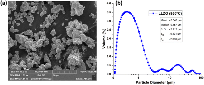
Comprehensive characterization of LLZO powders was carried out following thermal treatment at 950 °C prior to their incorporation into ceramic slurries for 3D printing.26 SEM analysis revealed that the Ta-doped LLZO particles exhibited an approximate size of 5 μm, with aggregation occurring within the range of 10–50 μm (Fig. 1). Conversely, PSD measurements indicated a d50 of approximately 0.5 μm for the powder, although larger aggregates were also evident. It's widely acknowledged that slurries containing ceramic particles with a uniform size distribution tend to exhibit enhanced stability and flowability. For example, Zhang et al.26 utilized Al2O3-based slurries composed of commercial powders characterized by spherical shape and narrow distribution. In our study, the powder morphology resembled those typically synthesized via the solid-state method. XRD analysis revealed that the powder pre-calcined at 950 °C contained both c- and t-LLZO phases, along with the presence of the La2Zr2O7 phase and trace amounts of Li2CO3. In our previous study, a two-step synthesis approach for LLZO was proposed, where the powder was initially pre-calcined at 950 °C to facilitate nucleation of the target phases. Subsequent treatment at higher temperatures led to the formation of a single-phase powder.23Pre-calcination serves two main purposes: first, it facilitates the production of powder with reduced specific surface area (SSA) and decreased hydrophilicity, thereby streamlining the slurry preparation process. Secondly, after additive manufacturing and debinding, it promotes the attainment of the desired phase through subsequent sintering.27,28 The pre-calcined powder exhibited an SSA of 1.2 m2 g−1 according to BET analysis (Fig. S1†), a parameter taken into account when adjusting dispersant amount during slurry preparation. Furthermore, the particle size distribution (Fig. 1), particularly the presence of a significant amount of fine particles, causes challenges in achieving uniform layer thickness and density during the SLA printing process.29 A broad particle size distribution, such as that indicated by the d90 of 2.09 μm, necessitates careful tuning of the printing parameters to achieve the desired balance between flowability and stability of the ceramic slurry. Optimizing these parameters is essential to prevent issues such as sedimentation or uneven layering, which are critical for achieving the mechanical and electrical integrity of the printed LLZO ceramics.30 In the context of SLA 3D printing for energy storage applications, the morphological characteristics of LLZO powders play a pivotal role. The efficacy of the printing process relies heavily on the consistency and stability of the ceramic slurry, crucial for producing high-precision and defect-free structures. The insights gained from the detailed analysis of LLZO powders can guide the development of advanced ceramic slurries, tailored for SLA 3D printing and thereby enhancing the performance and reliability of solid-state electrolytes in energy storage devices.31
The relationship between the specific surface area of LLZO particles and the utilization of surfactants provides valuable insights into slurry stabilization, a key aspect in SLA 3D printing. Adjusting surfactant levels based on surface area enhances the rheological properties of the slurry, promoting uniform layering during printing, which is crucial in preventing defects within the printed structures. Consistency and stability of the ceramic slurry are crucial for producing high-precision, defect-free structures. Insights from detailed analysis of LLZO powders can guide development of advanced ceramic slurries tailored for SLA 3D printing, enhancing performance and reliability of solid-state electrolytes in energy storage devices.32
3.2 Slurries properties
The preparation of a slurry with specific characteristics is a critical step in additive manufacturing of ceramics using vat polymerization techniques. In SLA/DLP 3D printing, it's essential to use suspensions that exhibit shear-thinning behavior and high solid loading to ensure defect-free fabrication of green bodies.33–35 The less viscous the suspension, the better the resolution, which also aids in the cleaning process. Conversely, higher solid contents are often necessary to achieve fully dense parts and prevent defects during debinding steps.36 However, incorporating ceramic fillers into photosensitive resin typically raises the viscosity of the slurry, which in turn decreases its flowability and makes the recoating process more difficult. It's essential during the manufacturing process to completely recoat the vat and ensure the slurry is evenly distributed before exposing it to UV light each time (each layer). Various ceramics, including zirconia, alumina, ATZ, or Ce:YAG, have been successfully fabricated via DLP 3D printing.37–39 This section aims to explore the choice of material for developing a slurry appropriate for DLP 3D printing of LLZO ceramic. Table 1 shows the composition of the slurries developed in the present work.| Materials | Composition in volume% | ||
|---|---|---|---|
| Slurry A | Slurry B | Slurry C | |
| LLZO | 41.8 | 41.6 | 40.16 |
| HDDA | 43.0 | 57.0 | 57.89 |
| PEGDA 250 | 13.3 | — | — |
| Dispersent BYK 2152 | 1.0 | 1.0 | 0.75 |
| TPO-L | 0.4 | 0.4 | — |
| Irgacure 1173 | — | — | 1.18 |
| Total | 100 | 100 | 100 |
In this study, Disperbyk 2152 was selected as the dispersant, with a dosage of 2.5 mg m−2 of LLZO powder utilized. This hyperbranched polymer is devoid of elements such as phosphorus, silica, or sodium, which could potentially diminish the ionic conductivity of the resultant ceramics.40 It is known that at elevated temperatures, these elements might migrate to the grain boundaries, adversely affecting the ionic conductivity, as observed in solid oxide fuel cells.41 In our previous study, we demonstrated the fabrication of fully dense and semi-translucent zirconia ceramics with high mechanical strength (1566 MPa). This was achieved using with relatively low-loaded slurries containing a binder system comprising a mixture of HDDA and PEGDA as a binder system.42 This approach has been replicated in the current study, aiming to develop appropriate photosensitive media for DLP 3D-printing of Ta-LLZO components. The rheological properties of the slurries prepared are depicted in Fig. 2. Unlike slurry A, formulations without PEGDA 250 exhibited shear-thinning behavior, which is suitable for vat polymerization processes.
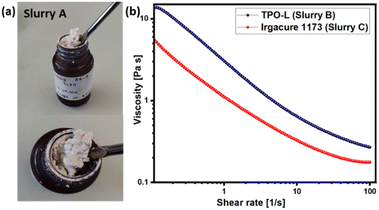 | ||
| Fig. 2 Rheological properties of the Ta-LLZO-based slurries: (a) slurry A with PEGDA 250, (b) slurries B and C with HDDA as a binder. | ||
In previous studies, it has been established that combining polyethylene glycol diacrylates with 1,6-hexanediol diacrylate can achieve a balance between low viscosity and favorable curing process.33,43 However, in the present work, we observed that the addition of LLZO powder to the monomer mixture resulted in a notably high viscosity paste, even with a low solid content of 35 vol%. M. L. Griffith and J. W. Halloran have noted that to ensure proper flow during recoating of each new layer, the suspension viscosity should remain below 3 Pa s at a shear rate of 30 s−1.44 Slurries containing TPO-L and Irgacure 1173 photo-initiators exhibited viscosities of 0.37 and 0.22 Pa s, respectively, at a shear rate of 30 s−1. Considering that the slurry containing a mixture of HDDA and PEGDA 250 did not exhibit the desired rheological behavior, it was decided to focus on the formulation with HDDA as the binder system. The selection of an appropriate photo initiator is essential for achieving desired results in additive manufacturing. When exposed to light, photo-initiators become active in the illuminated regions, producing free radicals that initiate the polymerization process.42 Typically these photo-initiators induce the formation of free radicals, initiating the polymerization of monomers. Polymerization continues under illumination until the suspension reaches the gel point, defining the depth at which curing occurs (referred to as the cure depth, Cd). In our study, we evaluated two types of photo-initiators: phosphine oxide TPO-L and ketone Igracure 1173. TPO-L is widely preferred in ceramic additive manufacturing for its high activity and its ability to function across a wide range of wavelengths, while Igracure 1173 requires a slightly shorter wavelength. Fig. 3 illustrates the cure depth of the slurries.
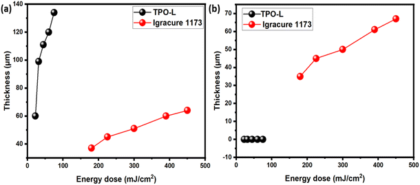 | ||
| Fig. 3 The cure depth of the slurries A and B: (a) cure depth of the as-prepared slurries, (b) cure depth in 5 days after preparation. | ||
As expected, the UV-light penetration depth notably increased in the slurries containing TPO-L as the photo initiator. Increasing the energy dose from 100 to 500 mJ cm−2 led to a rise in layer thickness from 60 to 140 μm. In contrast, Irgacure 1173 produced much thinner layers and required longer exposure times. However, it was observed that the slurry containing TPO-L lost its photo-activity entirely within a few days, with no curing observed within 5 days of slurry preparation. Furthermore, this trend persisted even after additional doses of TPO-L were added. Conversely, Irgacure 1173 exhibited lower activity but maintained consistent performance over time. We hypothesize that the absence of photocuring properties in the case of TPO-L might be attributed to interactions between the lithium in LLZO powder and the phosphoric group of the photoinitiator. Additionally, the significant difference in rheological behavior between pure HDDA and a mixture of HDDA–PEGDA suggests that LLZO powder may undergo chemical interactions with certain components in general.
3.3 Digital light processing
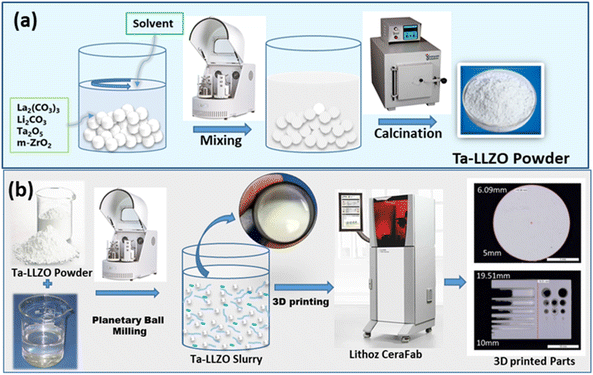
Therefore, the only formulation developed in this study that was suitable for additive manufacturing was slurry C, comprising Igracure 1173 and HDDA as a binder system. It is well known that the curing depth during printing must be at least twice the thickness of the layer to achieve proper interlayer binding. Accordingly, several parts were fabricated using the CeraFab 7500 machine with exposure times of 15 s per layer and a projector power of 18 mW cm−2. With this configuration, the energy dose per layer amounted to 270 mJ, ensuring the solidification of layers of 10 μm. Fig. 4 illustrates the 3D printing process and examples of the 3D printed parts.3.4 Debinding and sintering
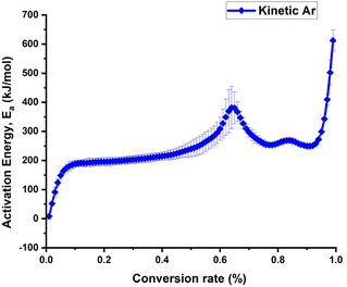
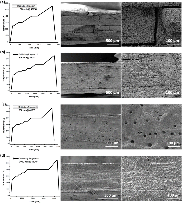
The design of an appropriate debinding profile is crucial for achieving a dense ceramic part in most of the additive manufacturing processes. During thermal debinding, organic compounds may undergo oxidation and decomposition, leading to an increase in internal pressure and the formation of defects such as pores or cracks. Fig. S2a† presents the decomposition of the cosslinked slurry C in different atmospheres. It can be observed, that the onset temperature for the debinding in synthetic air is lower and the slope of the mass loss is much steeper compared to the debinding process in nitrogen and argon. Previous studies have shown that performing debinding in an inert atmosphere can prevent the formation of these defects and avoid deformation of the final ceramic components.45 Therefore, the kinetic activation energy of the debinding process for the crosslinked slurry C based on TGA analyses performed at various heating rates (Fig. S2b†) was done under argon (Ar) atmosphere, and the results are shown in Fig. 5. For the debinding under inert atmosphere (argon) a steep increase of the activation energy at a conversion rate of 0.4 and a peak of the activation energy at the conversion rate of 0.65 have be observed. This corresponds to a temperature of around 320 °C and 400 °C, respectively.Based on the observed kinetics, we added an additional dwell time at 320 °C and 350 °C to the original debinding programme (Fig. 6b–d) and adjusted the debinding step to around 400 °C. After the sintering at 1150 °C for 6 h within a powder bed the microstructure was investigated by SEM analysis (Fig. 6). In debinding program 1(Fig. 6a), deformed shapes and cracks inside the samples were observed. In debinding program 2 (Fig. 6b), cracks were eliminated, but SEM images showed delamination within the layers. By increasing the dwell time to 800 min at a temperature of 410 °C a porous structures with a pore diameter of approximately 25 μm, with no evidence of layer delamination was observed (Fig. 6c). The large holes observed in Fig. 6c result from the rapid evolution of gases during the debinding phase. These gases, produced as the binder materials decompose, can create pores or voids if they do not escape from the material matrix in the printed LLZO structures. The porous structures of the previous program helped to achieve dense packing, facilitating capillary action for the LLZO particles in the 3D-printed shapes. However, by increasing the dwell time during the debinding process, the gas release rate can be slowed, allowing more time for the gas to escape gradually. This controlled release minimized the formation of defects, as shown in Fig. 6d after the sintering stage. Thus, the dwell time was further extended to 2000 minutes, and the temperature was lowered to 400 °C, resulting in defect-free 3D-printed LLZO structures (Fig. 6d).
3.5 Characterization 3D printed LLZO parts
Following the debinding and sintering processes of the 3D printed ceramics, the structural assessment of the resultant LLZO structures was carried out using X-ray powder diffraction (XRD). This analytical technique played a crucial role in understanding the phase formations influenced by the choice of photo-initiators. Distinctly, the sample incorporating the photo initiator Irgacure 1173 displayed an XRD pattern (Fig. 7a) that closely resonated with the reference pattern of LLZO, indicating a high degree of phase purity. In contrast, the XRD pattern of slurry B, with TPO-L as a photo initiator, diverged from this reference, underscoring the profound impact of photo-initiators on the crystalline integrity of the printed ceramics. The alignment of the Irgacure 1173 sample suggests its superior compatibility with the LLZO ceramic slurry and the sintering processes. This phase-pure LLZO structure, confirmed by XRD, establishes the Irgacure 1173 sample as a prime candidate for subsequent electrochemical investigations, potentially providing insights into its effectiveness in high-performance electrochemical applications.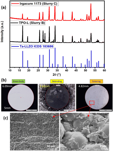 | ||
| Fig. 7 (a) XRD pattern of Ta-LLZO reference, slurry B and slurry C, (b) green body, debinded and sintered body for slurry C, and (c) SEM images of the sintered LLZO. | ||
Fig. 7b shows the green body after printing for the slurry C which underwent heat treatment (debinding program 4 from Fig. 6d) for the debinding and sintering process, revealing no visible defects or cracks in the SEM microstructural analysis (Fig. 7c) conducted at a higher magnification on LLZO pellets. The SEM image of printed and sintered LLZO reveals significantly higher density, indicating that the solid content is sufficient for achieving a highly dense final part. Importantly, no signs of heterogeneities, secondary phases, or decomposition products were detected through SEM analysis.
3.6 Electrochemical impedance spectroscopy (EIS) analysis
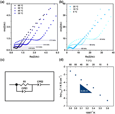
Following the validation of the 3D printed LLZO phase using X-ray powder diffraction (XRD), we assessed the LLZO electrochemical performance using Electrochemical Impedance Spectroscopy (EIS). EIS is widely used to determine the ionic conductivity of solid-state materials. The Ta-LLZO electrolyte discs were fabricated using a 3D printer, allowing precise control over their geometry and ensuring uniformity. For the test cell assembly, the 3D-printed Ta-LLZO disc was sandwiched between two lithium metal anodes using the following steps: placing the disc onto a steel plate for support and electrical contact, pressing a thin layer of lithium metal onto both sides of the disc to ensure good contact without damaging the brittle ceramic, and finally assembling the stack (steel plate|lithium|3D-printed Ta-LLZO disc|lithium|steel plate) for EIS measurement. The steel plates provided robust contact and a stable platform for electrochemical measurements. The 3D-printed discs were handled carefully to maintain their integrity and ensure consistent contact with the lithium anodes. The cell was tested in a symmetric configuration, measuring impedance response between the two lithium anodes. The Nyquist plots (Fig. 8a and b) exhibit distinct features. The high-frequency region displays a semicircle, attributed to the combined resistance and capacitance of the grain boundary and bulk material. The low-frequency region shows a spike, characteristic of a Li-ion blocking electrode system. This spike indicates a predominantly Li-ion conducting material with negligible electronic conductivity. In the Nyquist plots, the grain boundary's contribution was not detected at any temperature. Due to the difficulty in distinguishing the semicircle associated with the grain boundary from that associated with the grain, and the fact that the grain boundary semicircle was not evident, only the overall conductivities of the sample are presented in the Arrhenius plot. The total ionic resistance, which includes both lattice and grain boundary components, was determined using the equivalent circuit depicted in Fig. 8c. This resistance, combined with the sample dimensions, allowed for the calculation of the total ionic conductivity of the 3D-printed Ta-LLZO, as shown in Fig. 8d. The measured total ionic conductivity for the tetragonal LLZO phase was 3.15 × 10⁻⁵ S cm−1 at room temperature, which shows the high quality and of the synthesized material but also highlights the efficacy of the preparation and processing techniques employed. Ionic conductivity is a pivotal metric in gauging the potential of ceramic materials, especially for applications in solid-state batteries and electrochemical systems.18 The temperature dependence of the measured resistance was analyzed using an Arrhenius plot (Fig. 8d). The activation energy (Ea) for Li+ conduction through the bulk, grain boundaries, and interfaces was calculated based on the Arrhenius equation, yielding a value of 0.57 eV. The obtained conductivity and activation energy values, coupled with the previously confirmed phase purity, establishes a promising outlook for the LLZO sample's potential in high-performance electrochemical applications.46 Moving forward, efforts may concentrate on further optimizing this conductivity value. This could involve exploring different processing parameters or introducing dopant additions to fully exploit the material's potential in real-world applications.Galvanostatic cycling (GC) with varying current densities was performed on Li/LLZO/Li cells at 25 °C. The current densities resulting in short circuit formation of the cells are illustrated in Fig. S3 of the ESI document.† Traditionally, the CCD (cyclic charge–discharge) is identified as the point where the cell potential plummets to 0 V, signifying the formation of a lithium metal filament short circuit between the electrodes in another word where the Li dendrites are formed. Li/LLZO/Li cell formed short circuits at approximately current densities of 0.2–0.3 mA cm−2. Low polarization voltages (in mV range) at the beginning of the experiment suggests that the contact between Li electrodes and solid electrolyte was good however over the cycling higher voltages (in V range) a high level of scattering was observed indicating the worsening of the interface between Li and solid electrolyte. Also the gradual rise in voltage under a constant current density suggests that the dissolution and deposition of metallic lithium are occurring unevenly during the cycling process.
3.7 3D-printed custom LLZO fabrication
Solid-state lithium batteries, with their higher energy density and enhanced safety features, present a superior alternative to traditional lithium-ion batteries (LIBs), making them particularly suitable for use in electric vehicles and grid energy storage systems. However, current manufacturing techniques limit their practical energy density due to low areal capacities. To address this, thicker electrodes akin to those used in LIBs (30–100 μm) are proposed.47 These electrodes integrate the active material with an ionic conductor and an electronically conducting additive to enhance transport. We introduce a method for crafting such electrodes, starting with a porous scaffold, Li7La3Zr2O12 (LLZO), created via 3D printing using DLP technique. This scaffold features oriented channels with low tortuosity, facilitating lithium diffusion. The higher the surface area (pores) of the scaffold, the better the performance, and faster LLZO diffusion relative to the active materials leading to greater enhancement. Fig. 9 displays a CAD model presenting integrated dense-shaped pores, a 3D printed honeycomb porous structure, and a 3D printed integrated component, offering porous-dense-porous structures tailored for solid-state batteries.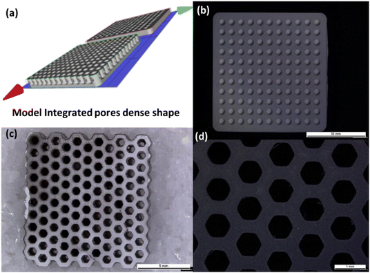 | ||
| Fig. 9 (a) CAD model featuring integrated dense-shaped pores, (b) a 3D printed integrated component, (c) and (d) 3D printed honeycomb porous Ta-LLZO structure. | ||
4 Conclusion
In our journey to revolutionize the 3D printing of ceramics, specifically focusing on the Ta-doped Li7La3Zr2O12, our research provides a comprehensive blueprint covering everything from formulation to electrochemical assessment. Central to our approach lies the carefully formulated slurry, tailored for the Digital Light Processing (DLP) 3D printing system. The meticulous inclusion of HDDA and PEGDA 250 binders, along with the strategic selection of photo-initiators, proved pivotal in ensuring not just a homogeneous suspension but also consistent photo-polymerization. Our investigation into the rheological properties of the slurry highlights the crucial role of viscosity in determining printability, layer uniformity, and overall 3D printing quality. This precision, combined with even particle distribution, facilitates a smooth transition from raw slurry to intricately designed ceramic structures. Post-processing, often overlooked, holds the key to the structural and functional integrity of the printed ceramic. Our thorough investigation into debinding unveiled the complexities of organic removal and the associated challenges. Through an iterative approach, we achieved an optimized debinding program which, when combined with the sintering phase, resulted in a densely packed 3D printed LLZO structure, setting the stage for subsequent evaluations. The validation of phase purity through XRD showcased the significant impact of photoinitiator selection. Notably, the slurry with Irgacure 1173 resulted in a phase pure XRD pattern suggesting its superior compatibility with LLZO ceramic slurry. However, this congruence was not the final goal. Subsequent EIS measurements, revealing an impressive ionic conductivity of 3.15 × 10⁻⁵ S cm−1, served as a testament to the quality of our slurry and the robustness of our printing and post-processing techniques. In summary, our research not only serves as a methodological roadmap for 3D printing ceramics but also showcases the harmonious integration of science, engineering, and design in achieving high-performance ceramic structures. As the field of 3D printed ceramics continues to evolve, we show that this innovative technology and processing can also be used for producing specifically designed pore and scaffold structures in solid state batteries from LLZO and other ceramic systems.Data availability
The data supporting this article have been included as part of the ESI.†Author contributions
Diwakar Karuppiah: methodology, investigation, visualization, writing – review & editing. Dmitrii Komissarenko: visualization, data curation. Tamanna Thakur: writing – original draft, data curation, formal analysis. Nur Sena Yüzbasi: formal analysis, writing – original draft. Frank Clemens: supervision, oftware, formal analysis, writing – review & editing. Elias Reisacher: formal analysis, Pinar Kaya: formal analysis, resources, validation. James Pikul: writing – review & editing, validation. Gurdial Blugan: conceptualization, supervision, resources, writing – review & editing.Conflicts of interest
The authors declare no apparent conflicting financial interests or personal relationships that could affect the findings presented in this study.Notes and references
- S. Chen, K. Wen, J. Fan, Y. Bando and D. Golberg, Progress and future prospects of high-voltage and high-safety electrolytes in advanced lithium batteries: from liquid to solid electrolytes, J. Mater. Chem. A, 2018, 6, 11631–11663, 10.1039/c8ta03358g.
- S. Wang, Y. Wu, T. Ma, L. Chen, H. Li and F. Wu, Thermal Stability between Sulfide Solid Electrolytes and Oxide Cathode, ACS Nano, 2022, 16, 16158–16176, DOI:10.1021/acsnano.2c04905.
- P. Albertus, V. Anandan, C. Ban, N. Balsara, I. Belharouak, J. Buettner-Garrett, Z. Chen, C. Daniel, M. Doeff, N. J. Dudney, B. Dunn, S. J. Harris, S. Herle, E. Herbert, S. Kalnaus, J. A. Libera, D. Lu, S. Martin, B. D. McCloskey, M. T. McDowell, Y. S. Meng, J. Nanda, J. Sakamoto, E. C. Self, S. Tepavcevic, E. Wachsman, C. Wang, A. S. Westover, J. Xiao and T. Yersak, Challenges for and Pathways toward Li-Metal-Based All-Solid-State Batteries, ACS Energy Lett., 2021, 6, 1399–1404, DOI:10.1021/acsenergylett.1c00445.
- N. Boaretto, I. Garbayo, S. Valiyaveettil-SobhanRaj, A. Quintela, C. Li, M. Casas-Cabanas and F. Aguesse, Lithium solid-state batteries: State-of-the-art and challenges for materials, interfaces and processing, J. Power Sources, 2021, 502, 229919, DOI:10.1016/j.jpowsour.2021.229919.
- G. R. Zhu, Q. Zhang, Q. S. Liu, Q. Y. Bai, Y. Z. Quan, Y. Gao, G. Wu and Y. Z. Wang, Non-flammable solvent-free liquid polymer electrolyte for lithium metal batteries, Nat. Commun., 2023, 14, 4617, DOI:10.1038/s41467-023-40394-8.
- J. Sastre, M. H. Futscher, L. Pompizi, A. Aribia, A. Priebe, J. Overbeck, M. Stiefel, A. N. Tiwari and Y. E. Romanyuk, Blocking lithium dendrite growth in solid-state batteries with an ultrathin amorphous Li-La-Zr-O solid electrolyte, Commun. Mater., 2021, 2, 76, DOI:10.1038/s43246-021-00177-4.
- W. Ping, C. Wang, R. Wang, Q. Dong, Z. Lin, A. H. Brozena, J. Dai, J. Luo and L. Hu, Printable, high-performance solid-state electrolyte films, Sci. Adv., 2020, 6, eabc8641, DOI:10.1126/sciadv.abc8641.
- R. A. Jonson, E. Yi, F. Shen and M. C. Tucker, Optimization of Tape Casting for Fabrication of Li6.25Al0.25La3Zr2O12 Sheets, Energy Fuels, 2021, 35, 8982–8990, DOI:10.1021/acs.energyfuels.1c00566.
- H. Sun, S. Kang and L. Cui, Prospects of LLZO type solid electrolyte: From material design to battery application, Chem. Eng. J., 2023, 454, 140375, DOI:10.1016/j.cej.2022.140375.
- M. Pei, H. Shi, F. Yao, S. Liang, Z. Xu, X. Pei, S. Wang and Y. Hu, 3D printing of advanced lithium batteries: a designing strategy of electrode/electrolyte architectures, J. Mater. Chem. A, 2021, 9, 25237–25257, 10.1039/d1ta06683h.
- Z. Liu, X. Tian, M. Liu, S. Duan, Y. Ren, H. Ma, K. Tang, J. Shi, S. Hou, H. Jin and G. Cao, Direct Ink Writing of Li(1.3) Al(0.3) Ti(1.7) (PO(4))(3) -Based Solid-State Electrolytes with Customized Shapes and Remarkable Electrochemical Behaviors, Small, 2021, 17, e2002866, DOI:10.1002/smll.202002866.
- S. Lawes, Q. Sun, A. Lushington, B. Xiao, Y. Liu and X. Sun, Inkjet-printed silicon as high performance anodes for Li-ion batteries, Nano Energy, 2017, 36, 313–321, DOI:10.1016/j.nanoen.2017.04.041.
- L. J. Deiner, T. Jenkins, T. Howell and M. Rottmayer, Aerosol Jet Printed Polymer Composite Electrolytes for Solid-State Li-Ion Batteries, Adv. Eng. Mater., 2019, 21(12), 1900952, DOI:10.1002/adem.201900952.
- C. Reyes, R. Somogyi, S. Niu, M. A. Cruz, F. Yang, M. J. Catenacci, C. P. Rhodes and B. J. Wiley, Three-Dimensional Printing of a Complete Lithium Ion Battery with Fused Filament Fabrication, ACS Appl. Energy Mater., 2018, 1(10), 5268–5279, DOI:10.1021/acsaem.8b00885.
- Y. He, S. Chen, L. Nie, Z. Sun, X. Wu and W. Liu, Stereolithography Three-Dimensional Printing Solid Polymer Electrolytes for All-Solid-State Lithium Metal Batteries, Nano Lett., 2020, 20, 7136–7143, DOI:10.1021/acs.nanolett.0c02457.
- X. Ye, C. Wang, L. Wang, B. Lu, F. Gao and D. Shao, DLP printing of a flexible micropattern Si/PEDOT:PSS/PEG electrode for lithium-ion batteries, Chem. Commun., 2022, 58, 7642–7645, 10.1039/d2cc01626e.
- Y. Zhao, J. Zhu, W. He, Y. Liu, X. Sang and R. Liu, 3D printing of unsupported multi-scale and large-span ceramic via near-infrared assisted direct ink writing, Nat. Commun., 2023, 14, 2381, DOI:10.1038/s41467-023-38082-8.
- D. W. McOwen, S. Xu, Y. Gong, Y. Wen, G. L. Godbey, J. E. Gritton, T. R. Hamann, J. Dai, G. T. Hitz, L. Hu and E. D. Wachsman, 3D-Printing Electrolytes for Solid-State Batteries, Adv. Mater., 2018, 30, e1707132, DOI:10.1002/adma.201707132.
- J. F. Valera-Jiménez, J. C. Pérez-Flores, M. Castro-García and J. Canales-Vázquez, Development of full ceramic electrodes for lithium-ion batteries via desktop-fused filament fabrication and further sintering, Appl. Mater. Today, 2021, 25, 101243, DOI:10.1016/j.apmt.2021.101243.
- A. G. Sabato, M. Nuñez Eroles, S. Anelli, C. D. Sierra, J. C. Gonzalez-Rosillo, M. Torrell, A. Pesce, G. Accardo, M. Casas-Cabanas, P. López-Aranguren, A. Morata and A. Tarancón, 3D printing of self-supported solid electrolytes made of glass-derived Li1.5Al0.5Ge1.5P3O12 for all-solid-state lithium-metal batteries, J. Mater. Chem. A, 2023, 11, 13677–13686, 10.1039/d3ta01435e.
- H. G. Hosseinabadi, D. Nieto, A. Yousefinejad, H. Fattel, L. Ionov and A. K. Miri, Ink Material Selection and Optical Design Considerations in DLP 3D Printing, Appl. Mater. Today, 2023, 30, 101721, DOI:10.1016/j.apmt.2022.101721.
- Y. Zhang, J. Deng, D. Hu, F. Chen, Q. Shen, L. Zhang and S. Dong, Synergistic regulation of garnet-type Ta-doped Li7La3Zr2O12 solid electrolyte by Li+ concentration and Li+ transport channel size, Electrochim. Acta, 2019, 296, 823–829, DOI:10.1016/j.electacta.2018.11.136.
- D. Karuppiah, D. Komissarenko, N. S. Yüzbasi, Y. Liu, P. V. Warriam Sasikumar, A. Hadian, T. Graule, F. Clemens and G. Blugan, A Facile Two-Step Thermal Process for Producing a Dense, Phase-Pure, Cubic Ta-Doped Lithium Lanthanum Zirconium Oxide Electrolyte for Upscaling, Batteries, 2023, 9(12), 591, DOI:10.3390/batteries9110554.
- M. Salehi, F. Clemens, T. Graule and B. Grobéty, Kinetic analysis of the polymer burnout in ceramic thermoplastic processing of the YSZ thin electrolyte structures using model free method, Appl. Energy, 2012, 95, 147–155, DOI:10.1016/j.apenergy.2012.02.025.
- H. L. Friedman, Kinetics of thermal degradation of char-forming plastics from thermogravimetry. Application to a phenolic plastic, J. Polym. Sci., Part C: Polym. Symp., 1964, 6, 183–195, DOI:10.1002/polc.5070060121.
- K. Zhang, C. Xie, G. Wang, R. He, G. Ding, M. Wang, D. Dai and D. Fang, High solid loading, low viscosity photosensitive Al2O3 slurry for stereolithography based additive manufacturing, Ceram. Int., 2019, 45, 203–208, DOI:10.1016/j.ceramint.2018.09.152.
- C. Hou, Y. Lu, L. Zhang, Y. Shan, C. Shao, J. Kang, D. Chen, Z. Wang, Y. Ma, Y. Li and H. Chen, Effective calcination pretreatment of Lu2O3 powders for LuAG transparent ceramics, Ceram. Int., 2021, 47, 6023–6029, DOI:10.1016/j.ceramint.2020.10.177.
- Sintering of Ceramics - New Emerging Techniques InTech, Janeza Trdine 9, 51000 Rijeka, Croatia, 2012.
- J. Sun, J. Binner and J. Bai, Effect of surface treatment on the dispersion of nano zirconia particles in non-aqueous suspensions for stereolithography, J. Eur. Ceram. Soc., 2019, 39, 1660–1667, DOI:10.1016/j.jeurceramsoc.2018.10.024.
- Z. Chen, J. Li, C. Liu, Y. Liu, J. Zhu and C. Lao, Preparation of high solid loading and low viscosity ceramic slurries for photopolymerization-based 3D printing, Ceram. Int., 2019, 45, 11549–11557, DOI:10.1016/j.ceramint.2019.03.024.
- S. Xu, M. Fang and X. Yan, Research on Rheology and Formability of SiO(2) Ceramic Slurry Based on Additive Manufacturing Technology via a Light Curing Method, ACS Omega, 2022, 7, 32754–32763, DOI:10.1021/acsomega.2c04541.
- X. Tian and B. Xu, 3D Printing for Solid-State Energy Storage, Small Methods, 2021, 5, e2100877, DOI:10.1002/smtd.202100877.
- I. L. d. Camargo, M. M. Morais, C. A. Fortulan and M. C. Branciforti, A review on the rheological behavior and formulations of ceramic suspensions for vat photopolymerization, Ceram. Int., 2021, 47, 11906–11921, DOI:10.1016/j.ceramint.2021.01.031.
- J. Deckers, J. Vleugels and J. P. Kruth, Additive manufacturing of ceramics a review, J. Ceram. Sci. Technol., 2014, 5, 245–260, DOI:10.4416/JCST2014-00032.
- J. J. Beaman, D. L. Bourell, C. C. Seepersad and D. Kovar, Additive Manufacturing Review: Early Past to Current Practice, J. Eng. Ind., 2020, 142(11), 110812, DOI:10.1115/1.4048193.
- M. Borlaf, A. Serra-Capdevila, C. Colominas and T. Graule, Development of UV-curable ZrO2 slurries for additive manufacturing (LCM-DLP) technology, J. Eur. Ceram. Soc., 2019, 39, 3797–3803, DOI:10.1016/j.jeurceramsoc.2019.05.023.
- L. V. Ermakova, V. V. Dubov, R. R. Saifutyarov, D. E. Kuznetsova, M. S. Malozovskaya, P. V. Karpyuk, G. A. Dosovitskiy and P. S. Sokolov, Influence of Luminescent Properties of Powders on the Fabrication of Scintillation Ceramics by Stereolithography 3D Printing, Ceramics, 2023, 6, 43–57, DOI:10.3390/ceramics6010004.
- D. Komissarenko, S. Roland, B. S. M. Seeber, T. Graule and G. Blugan, DLP 3D printing of high strength semi-translucent zirconia ceramics with relatively low-loaded UV-curable formulations, Ceram. Int., 2023, 49, 21008–21016, DOI:10.1016/j.ceramint.2023.03.236.
- T. Thakur, M. Carretta, D. Komissarenko and G. Blugan, Advancements in DLP 3D printing: High strength alumina toughened zirconia ceramics for biomedical applications, Open Ceram., 2024, 18, 100601, DOI:10.1016/j.oceram.2024.100601.
- W. Liu, H. Wu, Y. Xu, L. Lin, Y. Li and S. Wu, Cutting performance and wear mechanism of zirconia toughened alumina ceramic cutting tools formed by vat photopolymerization-based 3D printing, Ceram. Int., 2023, 49, 23238–23247, DOI:10.1016/j.ceramint.2023.04.153.
- M. Lankin, Y. Du and C. Finnerty, A Review of the Implications of Silica in Solid Oxide Fuel Cells, J. Fuel Cell Sci. Technol., 2011, 8(5), 054001, DOI:10.1115/1.4003980.
- J. W. Halloran, Ceramic Stereolithography: Additive Manufacturing for Ceramics by Photopolymerization, Annu. Rev. Mater. Res., 2016, 46, 19–40, DOI:10.1146/annurev-matsci-070115-031841.
- X. Li, J. Zhang, Y. Duan, N. Liu, J. Jiang, R. Ma, H. Xi and X. Li, Rheology and Curability Characterization of Photosensitive Slurries for 3D Printing of Si3N4 Ceramics, Appl. Sci., 2020, 10(18), 6438, DOI:10.3390/app10186438.
- M. L. Griffith and J. W. Halloran, Freeform Fabrication of Ceramics via Stereolithography, J. Am. Ceram. Soc., 2005, 79, 2601–2608, DOI:10.1111/j.1151-2916.1996.tb09022.x.
- J. Sun, J. Binner and J. Bai, 3D printing of zirconia via digital light processing: optimization of slurry and debinding process, J. Eur. Ceram. Soc., 2020, 40, 5837–5844, DOI:10.1016/j.jeurceramsoc.2020.05.079.
- J. Wolfenstine, E. Rangasamy, J. L. Allen and J. Sakamoto, High conductivity of dense tetragonal Li7La3Zr2O12, J. Power Sources, 2012, 208, 193–196, DOI:10.1016/j.jpowsour.2012.02.031.
- Z. Zhang, Y. Shao, B. Lotsch, Y.-S. Hu, H. Li, J. Janek, L. F. Nazar, C.-W. Nan, J. Maier, M. Armand and L. Chen, New horizons for inorganic solid state ion conductors, Energy Environ. Sci., 2018, 11, 1945–1976, 10.1039/C8EE01053F.
Footnote |
| † Electronic supplementary information (ESI) available. See DOI: https://doi.org/10.1039/d4ta06160h |
| This journal is © The Royal Society of Chemistry 2025 |

